Table of Contents
Advertisement
Quick Links
Download this manual
See also:
Operating Manual
Advertisement
Table of Contents

Related Manuals for CYP EL-41PIP


Summary of Contents for CYP EL-41PIP
- Page 1 EL-41PIP 4-Way HDMI Switch with Integrated Picture-in-Picture (PIP) Technology OPERATION MANUAL...
-
Page 3: Copyright Notice
DISCLAIMERS The information in this manual has been carefully checked and is believed to be accurate. CYP (UK) Ltd assumes no responsibility for any infringements of patents or other rights of third parties which may result from its use. CYP (UK) Ltd assumes no responsibility for any inaccuracies that may be contained in this document. -
Page 4: Safety Precautions
SAFETY PRECAUTIONS Please read all instructions before attempting to unpack, install or operate this equipment and before connecting the power supply. Please keep the following in mind as you unpack and install this equipment: • Always follow basic safety precautions to reduce the risk of fire, electrical shock and injury to persons. -
Page 5: Table Of Contents
CONTENTS 1. Introduction ...........6 2. Applications ...........6 3. Package Contents ........6 4. System Requirements ......6 5. Features ..........7 6. Operation Controls and Functions ..8 6.1 Front Panel ........... 8 6.2 Rear Panel ............. 9 6.3 Remote Control ........10 6.4 RS-232 Protocols ........11 6.5 RS-232 and Telnet Commands ....12 6.6 OSD Menu ..........16 6.7 Telnet Control ..........22... -
Page 6: Introduction
1. INTRODUCTION The EL-41PIP is an advanced 4 Way HDMI switch with integrated Multi- view (Picture In Picture) technology. This plug and play solution offers advanced control and display options for the integration of 4 sources onto a single display. The EL-41PIP is the perfect cost effective solution for integrating CCTV or a combination of sources into any single display within any commercial or residential AV installation. -
Page 7: Features
5. FEATURES Integration of up to 4 sources on a single display Multiple screen layout configurations Seamless switching of channels and on screen windows Fade in out display functionality Ability to mirror and rotate images Zoom & Shrink HDMI Video and/or Overlay Resolutions supported : -HDTV: 480i to 1080p plus 1080p24fps -PC: VGA to UXGA... -
Page 8: Operation Controls And Functions
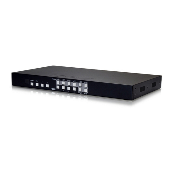
6. OPERATION CONTROLS AND FUNCTIONS 6.1 Front Panel WINDOW POWER MENU CHANNEL INPUT 1 2 3 4 2 3 4 IR WINDOW: Accepts the IR signal from the supplied remote control. POWER: Press to turn the unit on or to put it into standby mode. MENU Button: Press this button to bring up the On-screen Display (OSD) menu on screen. -
Page 9: Rear Panel
6.2 Rear Panel HDMI IN HDMI OUT CONTROL RS232 DC 12V SERVICE ONLY HDMI IN 1~4: Connect to up to four source HDMI equipped source devices such as DVD/Blu-ray players and or PC/Laptop devices. HDMI OUT: Connect to a HD TV/monitor or HDMI matrix for display of the image. -
Page 10: Remote Control
6.3 Remote Control Power: Press this button to switch the Info Power device on or to set it to standby mode. CH 1 CH 2 Info: Press this button to display the CH 3 device’s firmwareersion. CH 4 Input CH 1/2/3/4: Press these buttons Mute Input to cycle through the HDMI sources (1 to... -
Page 11: Rs-232 Protocols
6.4 RS-232 Protocols UNIT Remote Control Assignment Assignment Baud Rate: 115,200 bps Data Bit: 8 bits Parity: None Flow Control: None Stop Bit: 1... -
Page 12: Rs-232 And Telnet Commands
6.5 RS-232 and Telnet Commands Command Description RESO 0~18 SET OUTPUT RESOLUTION (0) 480p, (1) 576p, (2) 720p 50Hz, (3) 720p 60Hz, (4) 1080p 24Hz, (5) 1080p 25Hz, (6) 1080p 30Hz, (7) 1080p 50Hz, (8) 1080p 60Hz, (9) 1024x768 60Hz, (10) 1280x800 60Hz, (11) 1280x1024 60Hz, (12) 1366x768 60Hz, (13) 1440x900 60Hz, (14) 1600x900 60Hz, (15)1600x1200 60Hz, (16) 1680x1050 60Hz, (17)1920x1200 60Hz, (18) Native... - Page 13 Command Description HSIZE 1~4 0~X** SET IMAGE HORIZONTAL SIZE (1~4) CHANNEL, (0~X) X=HORIZONTAL PIXEL FOR CURRENT RESOLUTION VSIZE 1~4 0~X** SET IMAGE VERTICAL SIZE (1~4) CHANNEL, (0~X) X=VERTICAL PIXEL FOR CURRENT RESOLUTION HPOS 1~4 0~X** SET HORIZONTAL POSITION OF SPECIFIED CHANNEL (1~4) CHANNEL, (0~X) X=HORIZONTAL PIXEL FOR CURRENT RESOLUTION VPOS 1~4 0~X**...
- Page 14 Command Description ROTATE 0~3* SET VIDEO ROTATION VIDEO TO PRESET POSITIONS (0) ROTATE OFF, (1) R90, (2) L90, (3) 180 CHRC R/G/B MIN/ SET THE RGB COLOUR RANGE FOR THE CHROMA KEY MAX 0~255* (R/G/B) COLOUR CHANNEL (MIN/MAX) COLOUR VALUE ++(0~15) SET PRESENT VALUE 0~255 RBG MAX (0)15, (1)31, (2)47, (3)63, (4)79, (5)95, (6)111, (7)127,...
- Page 15 Command Description CH2004 Change CH2 to Source 4 CH3001 Change CH3 to Source 1 CH3002 Change CH3 to Source 2 CH3003 Change CH3 to Source 3 CH3004 Change CH3 to Source 4 CH4001 Change CH4 to Source 1 CH4002 Change CH4 to Source 2 CH4003 Change CH4 to Source 3 CH4004...
- Page 16 Command Description ROT001* Rotation Function R ROT002* Rotation Function L ROT003* Rotation Function Up-Side Down SFA001** Store window format to FAV 1 SFA002** Store window format to FAV 2 SFA003** Store window format to FAV 2 SFA004** Store window format to FAV 4 RFA001** Recall window from FAV 1 RFA002**...
- Page 17 Command Description POW 0/1 POWER THE UNIT ON/OFF (0) OFF, (1) ON AUDIO 1~4 CHANGE OUTPUT AUDIO TO SPECIFIED SOURCE (1~4) AUDIO SOURCE IMRE B/C/S/H RESET THE IMAGE TO FACTORY DEFAULTS (B) BRIGHTNESS, (C) CONTRAST, (S) SATURATION, (H) HUE PIRE RESET THE UNIT PICTURE SETTINGS TO FACTORY DEFAULTS CHRE 0~4** RESET THE WINDOWS SETTINGS TO FACTORY DEFAULTS...
-
Page 18: Osd Menu
6.6 OSD Menu Main Menu Layer Layer Layer 480P, 579P, 720P50/60, 1080P24/25/30/50/60, 1024x768, 1280x800, 1280x1024, 1366x768, I/O Setup Output Resolution 1440x900, 1600x900, 1600x1200, 1680x1050, 1920x1200, NATIVE Menu Back Info Display On/Off H Offset 0~20 (5) V Offset 0~20 (5) OSD Settings Off~50 Timeout Gain... - Page 19 Main Menu Layer Layer Layer CH1 Wxxx Hxxx Width Unit Width Ten Size Width Hundred Height Unit Height Ten Height Hundred CH1 Hxxx Vxxx Channel 1 Select Horizontal Unit Horizontal Ten Position Horizontal Hundred Vertical Unit Vertical Ten Vertical Hundred On/Off Image Output CH1→4,CH2→3,...
- Page 20 Main Menu Layer Layer Layer CH3 Wxxx Hxxx Width Unit Width Ten Size Width Hundred Height Unit Height Ten Height Hundred CH3 Hxxx Vxxx Horizontal Unit Channel 3 Select Horizontal Ten Position Horizontal Hundred Vertical Unit Vertical Ten Vertical Hundred On/Off Image Output CH1→4,CH2→3,...
- Page 21 Main Menu Layer Layer Layer Window VIDEO 1/2/3/4 Setup VIDEO 1 (Cont.) VIDEO 2 VIDEO 1/2/3/4 Label Select VIDEO 3 VIDEO 1/2/3/4 VIDEO 4 VIDEO 1/2/3/4 Menu Exit FAV 1 Store ON/OFF/OK FAV 2 Store ON/OFF/OK Favours Store FAV 3 Store ON/OFF/OK FAV 4 Store ON/OFF/OK...
- Page 22 Main Menu Layer Layer Layer Mirror On/Off Off/1.0/1.1/1.2 Convert /1.3/1.4/1.5/1. 6/1.7/1.8/1.9/2.0/2.1/2 Fade In-Out Channel 3 Convert 2.3/2.4/2.5/2.6/ 2.7/2.8/2.9/3.0 R90/L90/Up-Side Rotation Down180/Off Window Reset Window Convert Menu Exit Mirror On/Off (Cont.) Off/1.0/1.1/1.2 Convert /1.3/1.4/1.5/1. 6/1.7/1.8/1.9/2.0/2.1/2 Fade In-Out Channel 4 Convert 2.3/2.4/2.5/2.6/ 2.7/2.8/2.9/3.0 R90/L90/Up-Side Rotation...
- Page 23 Main Menu Layer Layer Layer IP Mode Static/DHCP Static Set IP/Mask/Gate XXX 192 255 192 Byte1 High 000~255 XXX 168 255 168 Byte2 000~255 XXX 5 255 5 Byte3 000~255 XXX 159 0 254 Byte4 Low 000~255 Ethernet No/Yes Re-Link Exit Setup Static/DHCP IP...
-
Page 24: Telnet Control
6.7 Telnet Control Before attempting to use the telnet control, please ensure that both the Scaler (via the ‘CONTROL’ port) and the PC/Laptop are connected to the active networks. To access the telnet control in Windows 7, click on the ‘Start’ menu and type “cmd”... - Page 25 This will bring us into the device which we wish to control. Type “?” to lists all the available commands. Type “IPCONFIG” To show all IP configurations. To reset the IP, type “IPMODE” to set static IP/DHCP (For a full list of commands, see Section 6.6). Note: Commands will be not executed unless followed with a carriage return.
-
Page 26: Webgui Control
6.8 WebGUI Control On a PC/Laptop that is connected to the same active network as the Scaler, open a web browser and type the device’s IP address on the web address entry bar. The browser will display the device’s Image Adjust, Output Resolution, etc. - Page 27 Click on the ‘Windows Setup’ tab to set the output display format. Note: This function is only available under window E~H. Click on the ‘OSD Settings’ tab to set the OSD function and position.
- Page 28 Click on the ‘Window Convert’ tab to set the output display angle. Note: This function is only available under window A~D. Click on the ‘Chromakey Setup’ tab to set the output display colour. Note: This function is only available under window E~H.
- Page 29 Click on the ‘Ethernet’ tab to reset the IP configuration. The system will ask for a reboot of the device when any of these settings are changed. The IP address needed to access the Web GUI control will also need to be changed accordingly on the web address entry bar.
-
Page 30: Connection Diagram
7. CONNECTION DIAGRAM HDMI Camera Blu-ray Player Set-top Box Games Console HDMI Inputs Router Smartphone or Tablet 4 3 2 1 Device Power HDMI IN HDMI OUT CONTROL RS232 DC 12V SERVICE Supply ONLY HDMI Output RS-232 RS-232 Enabled PC/Laptop or Control System HDTV Screen Configurations:... -
Page 31: Specifications
8. SPECIFICATIONS 8.1 Technical Specifications Video Bandwidth 225 MHz/6.75 Gbps Input Ports 4× HDMI Output Port 1× HDMI Supported Input Resolutions PC:VGA~WUXGA, HD: 480i~1080p Supported Output Resolutions 1080p@60 HDMI Input Cable Distance Up to 15m/1080p@12 bits HDMI Output Cable Distance Up to 15m/1080p@8 bits Supports Sampling Rate 32~192 kHz... -
Page 32: Supported Resolutions
8.2 Supported Resolutions HDMI RESOLUTIONS INPUT OUTPUT 640x480@60/72/75/85 800x600@56/60/72/75/85 1024x768@60/70/75/85 1024x768@60 1360x768@60 1280x768@60/75 1280x800@60 1280x1024@60/75 1280x1024@60 1366x768@60 1440x900@60 1600x900@60 1600x1200@60 1680x1050@60 1920x1200@60 480i60 576i50 ... -
Page 33: Acronyms
9. ACRONYMS ACRONYM COMPLETE TERM Consumer Electronics Control Digital V isual Interface HDCP High-bandwidth Digital Content Protection HDMI High Definition Multimedia Interface Picture-in-Picture Picture out of picture Infrared... - Page 36 CYP (UK) Ltd., Unit 7, Shepperton Business Park, Govett Avenue, Shepperton, Middlesex, TW17 8BA Tel: +44 (0) 20 3137 9180 | Fax: +44 (0) 20 3137 6279 Email: sales@cypeurope.com www.cypeurope.com v1.02...
Need help?
Do you have a question about the EL-41PIP and is the answer not in the manual?
Questions and answers