Digital i/o board with opto-isolation for pci, digital input board with opto-isolation for pci, digital output board with opto-isolation for pci (71 pages)
Digital i/o board with opto-isolation for pci
pio-32/32l(pci)h
digital input board with opto-isolation for pci
pi-64l(pci)h
digital output board with opto-isolation for pci
po-64l(pci)h (71 pages)
Page 1
PC-HELPER 
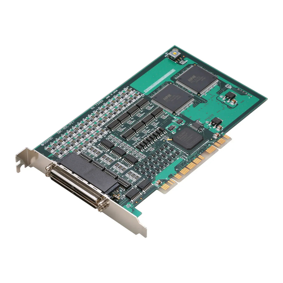
High-Speed Motion Control Board for PCI (4ch) SMC-4DL-PCI (8ch) SMC-8DL-PCI User’s Guide CONTEC CO.,LTD.
Page 2
Check Your Package Thank you for purchasing the CONTEC product. The product consists of the items listed below. Check, with the following list, that your package is complete. If you discover damaged or missing items, contact your retailer. Product Configuration List - Board (One of the following) [SMC-4DL-PCI or SMC-8DL-PCI] …1...
No part of this document may be copied or reproduced in any form by any means without prior written consent of CONTEC CO., LTD. CONTEC CO., LTD. makes no commitment to update or keep current the information contained in this document. The information in this document is subject to change without notice.
Selecting API-SMC(WDM) ...................... 10 Executing the Installation ......................10 Step 2 Setting the Hardware ......................11 Parts of this product and Factory Defaults ................11 Setting the Board ID ........................13 Setting the Terminating Registor....................13 Plugging the Board ........................14 SMC-4DL-PCI, SMC-8DL-PCI...
Page 5
Limit input signals ........................42 Encoder input signal ........................43 Pulse output signal ........................44 General-purpose input signals ....................45 General-purpose output signals ....................46 P.COM (Plus common)......................46 GND (Ground) ........................... 46 Motion control system ........................47 System configuration ......................... 47 SMC-4DL-PCI, SMC-8DL-PCI...
Page 6
ABOUT SOFTWARE CD-ROM Directory Structure ......................49 About Software for Windows......................50 Accessing the Help File ......................50 Uninstalling the Driver library ....................51 ABOUT HARDWARE For detailed technical information ....................53 Hardware specification ........................53 Block Diagram..........................56 SMC-4DL-PCI, SMC-8DL-PCI...
X-Y robots. The < SMC-4DL-PCI > can control up to four axes alone. The < SMC-8DL-PCI > can control up to eight axes alone. Using the bundled driver library [API-PAC(W32)], you can create Windows application software for this board in your favorite programming language supporting Win32 API functions, such as Visual Basic or Visual C++.
You should use CONTEC support software according to your purpose and development environment. Driver Library API-PAC(W32) (Bundled) API-PAC(W32) is the library software that provides the commands for CONTEC hardware products in the form of Windows standard Win32 API functions (DLL). It makes it easy to create high-speed application software taking advantage of the CONTEC hardware using various programming languages that support Win32 API functions, such as Visual Basic and Visual C++.
You can download updated driver software and differential files as well as sample programs available in several languages. Note! For product information Contact your retailer if you have any technical question about a CONTEC product or need its price, delivery time, or estimate information. Limited Three-Years Warranty CONTEC products are warranted by CONTEC CO., LTD.
WARNING indicates a potentially hazardous situation which, if not avoided, could WARNING result in death or serious injury. CAUTION indicates a potentially hazardous situation which, if not avoided, may CAUTION result in minor or moderate injury or in property damage. SMC-4DL-PCI, SMC-8DL-PCI...
Even when using this product continuously, be sure to read the manual and understand the contents. Do not modify this product. CONTEC will bear no responsibility for any problems, etc., resulting from modifying this product. Regardless of the foregoing statements, CONTEC is not liable for any damages whatsoever (including damages for loss of business profits) arising out of the use or inability to use this CONTEC product or the information contained herein.
(3) Store the package at room temperature at a place free from direct sunlight, moisture, shock, vibration, magnetism, and static electricity. Disposal When disposing of the product, follow the disposal procedures stipulated under the relevant laws and municipal ordinances. SMC-4DL-PCI, SMC-8DL-PCI...
For setting up software other than API-PAC(W32), refer to the manual for that software. See also the following parts of this manual as required. This chapter Step 2 Setting the Hardware This chapter Step 3 Installing the Hardware Chapter 3 External Connection Chapter 6 About Hardware SMC-4DL-PCI, SMC-8DL-PCI...
Using the Board under an OS Other than Windows For using the board under an OS other than Windows, see the following parts of this manual. This chapter Step 2 Setting the Hardware Chapter 3 External Connection Chapter 6 About Hardware SMC-4DL-PCI, SMC-8DL-PCI...
If the panel does not appear, run (CD-ROM drive letter):\AUTORUN.exe. (3) Click on the [Install Development or Execution Environment] button. CAUTION Before installing the software in Windows XP, Server 2003, 2000, log in as a user with administrator privileges. SMC-4DL-PCI, SMC-8DL-PCI...
(2) Select the "High Functionality WDM Motor Control driver". (3) Click on the [Install] button. Executing the Installation (1) Follow the on-screen instructions to proceed to install. (2) After finishing installing, Readme file is displayed. You have now finished installing the software. SMC-4DL-PCI, SMC-8DL-PCI...
Setup Method To select whether to insert the terminator, use the DIP switches (SMC-4DL-PCI : SW2 and SW3, SMC-8DL-PCI : SW2 - SW5) on the board. Set SW2 and SW3 according to the figure shown below. 1 2 3 4 5 6 7 8...
Make sure that your PC or expansion unit can supply ample power to all the boards installed. Insufficiently energized boards could malfunction, overheat, or cause a failure. Power supply from the PCI bus slot at +5V is required. SMC-4DL-PCI, SMC-8DL-PCI...
In this case, you must check the resource settings. When Using API-SMC(WDM) (1) The “Found New Hardware Wizard” will be started. Select “Install from a list or specific location[Advanced]”, then click on the [Next] button. SMC-4DL-PCI, SMC-8DL-PCI...
Page 23
* The name of the board you have just added is displayed. - SMC-4DL-PCI - SMC-8DL-PCI Source folder The setup information (INF) file is contained in the following folder on the bundled CD-ROM. \INF\WDM\SMC \INF\WDM\SMC You have now finished installing the hardware.
- SMC-4DL-PCI - SMC-8DL-PCI (2) The installed hardware appears under the CONTEC Devices node. Open the CONTEC Devices node and select the device you want to setup (the device name should appear highlighted). Click [Properties]. SMC-4DL-PCI, SMC-8DL-PCI...
Page 25
- SMC-4DL-PCI - SMC-8DL-PCI The initial device name that appears is a default value. You can use this default name if you wish. Make sure that you do not use the same name for more than one device.
For direct connection to the board, see Chapter 3 “External Connection”. Connection diagram The following connection diagrams show connections using the dedicated screw terminal CCB-SMC2. <Pulse output> CCB-SMC2 Driver Unit CCW+ CCW+ CCW- CCW- Figure 2.5. Connection diagram < 1 / 2 > SMC-4DL-PCI, SMC-8DL-PCI...
* The name of the board you have just added is displayed. - SMC-4DL-PCI - SMC-8DL-PCI Checking for motor control (1) Select the name of the axis you want to diagnose, then click on the [Execute Initial Setup Utility] button to execute Quick Check.
Page 29
(2) Check/mask each signal. When the alarm (ALM/ES) is ON or each limit (+LIM, -LIM) is ON, the motor does not operate in that direction. In this case, check the connection of the signal or mask it. SMC-4DL-PCI, SMC-8DL-PCI...
Refer to the source code for the sample programs. The OS does not boot correctly or does not detect the device correctly. Refer to the "Troubleshooting" section of API-SMC(WDM) HELP. If your problem cannot be resolved Contact your retailer. SMC-4DL-PCI, SMC-8DL-PCI...
KOGYO CO., LTD] * Please refer to chapter 1 for more information on the supported cable and accessories. Figure 3.1. Interface Connector Shape < SMC-8DL-PCI > < SMC-4DL-PCI > The on-board interface connector (CN1) is used when connecting this product and the external devices.
Figure 3.5. Pulse output circuit (Connection with the differential input) Connection with the opto-coupler input (When the driver unit guarantees the connection with the differential output) Driver Unit Board AM26LS31 or equivalence to it CCW+ CCW- Figure 3.6. Pulse output circuit (connection with the opto-coupler input) SMC-4DL-PCI, SMC-8DL-PCI...
Page 40
When connecting with the photo-coupler input or the TTL level input, check the specification for the driver unit beforehand. To prevent the circuit from malfunctioning due to noise, wire it as far away from other signal lines and noise sources as possible. SMC-4DL-PCI, SMC-8DL-PCI...
Output circuit of each output signal on this product is illustrated below. The signal output is an open-collector output. A ground wire must therefore be connected for driving. Board Driver Unit OUT1 - OUT3 +12 - +24VDC Figure 3.9. Output circuit SMC-4DL-PCI, SMC-8DL-PCI...
Connection with the differential output Board Driver Unit AM26LS31 or equivalence to it Phase A+ Phase A- AM26LS31 or equivalence to it Phase B+ Phase B- AM26LS31 or equivalence to it Phase Z+ Phase Z- Figure 3.10. Encoder input circuit SMC-4DL-PCI, SMC-8DL-PCI...
Page 43
Board Driver Unit TTL level AM26LS31 or output equivalence to it Phase A+ TTL level AM26LS31 or output equivalence to it Phase B+ TTL level AM26LS31 or output equivalence to it Phase Z+ Figure 3.11. Encoder input circuit SMC-4DL-PCI, SMC-8DL-PCI...
Page 44
Restrict the use of cables to 10m for the line driver output, 3m for the open-collector output, and 1.5m for the TTL level output. To prevent the circuit from malfunctioning due to noise, wire it as far away from other signal lines and noise sources as possible. SMC-4DL-PCI, SMC-8DL-PCI...
(40) OUT2 (65) /ALM-RST (44) (18) (15) OUT3 (66) /CLR (14) CW+ (61) PLUS (60) /PLUS CCW+ (63) SIGN (11) CCW- (62) /SIGN (12) Figure 3.14. Example of Connection to driver unit (Σ II Series) for Servo motor SMC-4DL-PCI, SMC-8DL-PCI...
OUT 1 - 3 Surge current Resistor prevention resistor Figure 3.15. Surge Voltage Countermeasure CAUTION In order for a protection circuit to operate effectively, it must be connected within 50 cm of a load and a contact point. SMC-4DL-PCI, SMC-8DL-PCI...
This product has the S-curve acceleration/deceleration function in addition to the linear acceleration/deceleration function. The S-curve acceleration/deceleration function reduces acceleration when starting and stopping accelerating/decelerating the motor, thereby suppressing the vibration generated at the start and end of motion. SMC-4DL-PCI, SMC-8DL-PCI...
The logical direction can be set by software. ORG (origin input) ORG is the switch input to detect the origin to be set as the base point for each operation. The logical direction can be set by software. SMC-4DL-PCI, SMC-8DL-PCI...
A count cannot be performed properly, if Phase A (UP) pulse and Phase B (DOWN) pulse are generated at the same time. U : Up Count D : Down Count Figure 4.3. Sample Count for Single-phase Input Setting SMC-4DL-PCI, SMC-8DL-PCI...
The CW and CCW directions are indicated by the signal status of DIR (direction output). Note that the DIR signal is valid only when the OUT signal is active. When positive direction operates When negative direction operates Figure 4.5. Specification for Output Pulse in Common Pulsing Method SMC-4DL-PCI, SMC-8DL-PCI...
INP is the signal to detect the positioning completion signal from the motor driver unit. The input logic can be changed by software. SD (deceleration (decelerated stop) input) SD is a signal to detect the position at which to start deceleration. The input logic can be changed by software. SMC-4DL-PCI, SMC-8DL-PCI...
P.COM is the plus common signal for limit input signals (+LIM, -LIM, SD, ORG) and general-purpose input/output signals (IN1 - IN7, OUT1 - OUT3). GND (Ground) GND is the ground line for the general-purpose output signals (OUT1 - OUT3). SMC-4DL-PCI, SMC-8DL-PCI...
When a table is used in the system, the sensor is bundled with the table. For a self-made system, use commercially available switches. DC Power supply Power supply to the CCB-SMC2. Use a 12 - 24-VDC power supply. (Power supply maker) SMC-4DL-PCI, SMC-8DL-PCI...
|––Win95 |––linux Driver file for Linux |––cnt |––dio |––…… | ––Readme Readme file for each driver | ––Release Driver file on each API-TOOL |––API_NT (For creation of a user-specific install program) |––API_W95 |––UsersGuide Hardware User's Guide (PDF files) SMC-4DL-PCI, SMC-8DL-PCI...
Reference”, “Sample Programs”, and “Q&A”. Use them for program development and troubleshooting. Accessing the Help File (1) Click on the [Start] button on the Windows taskbar. (2) From the Start Menu, select “Programs” – “CONTEC API-PAC(W32)” - “SMC” - “API-SMC-D HELP” to display help information. SMC-4DL-PCI, SMC-8DL-PCI...
(2) Double-click on “Add/Remove Programs” in the Control Panel. (3) Double-click on “Add or Remove Programs” in the Control Panel. Select “CONTEC API-SMC(WDM) driver” from the application list displayed, then click on the [Change/Remove] button. Follow the on-screen instructions to uninstall the function libraries.
Page 59
5. About Software SMC-4DL-PCI, SMC-8DL-PCI...
This chapter provides hardware specifications and hardware-related supplementary information. For detailed technical information For further detailed technical information (“Technical Reference” including the information such as an I/O map, configuration register, etc.), visit the Contec's web site (http://www.contec.com/support/) to call for it. Hardware specification Tables 6.1 - 6.6 list the hardware specifications of the board.
Page 61
Opto-coupler input (corresponding to current sink output) Input type Response time (Max.) 200 µ sec Input resistance 4.7k Ω Input ON current 2.0mA or more Input OFF current 0.16mA or less External circuit power supply 12V - 24VDC(±10%) SMC-4DL-PCI, SMC-8DL-PCI...
Page 62
(Enables selecting the positive/negative logic by using the Software) Response time (Max.) 10 µ sec (when using the loading on the input side 510 Ω , +24VDC) Rated output current (Max.) 100mA per 1ch, 300mA per 1axis Rated output withstanding 50VDC voltage (Max.) SMC-4DL-PCI, SMC-8DL-PCI...
Page 64
3-9-31, Himesato, Nishiyodogawa-ku, Osaka 555-0025, Japan Japanese http://www.contec.co.jp/ English http://www.contec.com/ Chinese http://www.contec.com.cn/ No part of this document may be copied or reproduced in any form by any means without prior written consent of CONTEC CO., LTD. [10172006] [07252006] Management No. A-51-263 [10172006] Parts No.