
Related Manuals for Contec CNT24-4(PCI)


Summary of Contents for Contec CNT24-4(PCI)
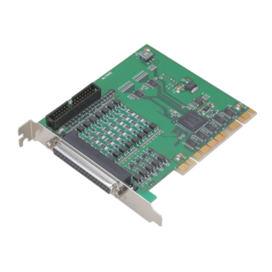
- Page 1 PC-HELPER 4ch 24Bit Up/Down Counter Board for PCI CNT24-4(PCI)H User’s Guide CONTEC CO.,LTD.
- Page 2 Check Your Package Thank you for purchasing the CONTEC product. The product consists of the items listed below. Check, with the following list, that your package is complete. If you discover damaged or missing items, contact your retailer. Product Configuration List - CNT24-4(PCI)H …1...
-
Page 3: Copyright
No part of this document may be copied or reproduced in any form by any means without prior written consent of CONTEC CO., LTD. CONTEC CO., LTD. makes no commitment to update or keep current the information contained in this document. The information in this document is subject to change without notice. -
Page 4: Table Of Contents
Selecting the Counter Board Driver ..................12 Executing the Installation ......................13 Step 2 Setting the Hardware ......................14 Parts of the Board and Factory Defaults ................... 14 Setting the Board ID ........................15 Plugging the Board ........................16 CNT24-4(PCI)H... - Page 5 TTL-Level Input Circuit ......................35 Example Connection with a Rotary Encoder ................36 Example Connection with a Linear Scale.................. 36 One-shot Pulse Output Connection ....................37 One-shot Pulse Output Connection ................... 37 Output Circuit and an Example Connection................37 Surge Voltage Countermeasures....................... 38 CNT24-4(PCI)H...
- Page 6 About Software for Linux......................... 53 Driver Software Install Procedure ..................... 53 Accessing the Help File ......................54 Using Sample Programs ......................54 Uninstalling the driver ....................... 54 ABOUT HARDWARE Hardware specification ........................55 Block Diagram..........................56 Differences between CNT24-4(PCI)H and CNT24-4(PCI) ............. 57 CNT24-4(PCI)H...
- Page 7 CNT24-4(PCI)H...
-
Page 8: Before Using The Product
The CNT24-4(PCI)H is a PCI bus-compliant interface board that counts input pulse signals from external devices. The CNT24-4(PCI)H has four channels of 24-bit up/down counters, allowing external devices such as a rotary encoder and a linear scale to be connected. Given below are examples of using the board for “detecting a position of the table of a machine tool”... -
Page 9: Support Software
This driver is used to control CONTEC counter boards (PC Cards). You can control CONTEC counter boards easily using the shared library used by gcc, Kylix, the device driver (module) for each kernel version, and the board (PC Cards) configuration program (config). -
Page 10: Cable & Connector (Option)
Screw terminal (Screw Up type) : EPD-37 *1 Terminal unit for solderless terminal (M3) : DTP-3(PC) Terminal unit for leads : DTP-4(PC) *1 Option cable PCB37P or PCB37PS is required separately. Check the CONTEC’s Web site for more information on these options. CNT24-4(PCI)H... -
Page 11: Customer Support
You can download updated driver software and differential files as well as sample programs available in several languages. Note! For product information Contact your retailer if you have any technical question about a CONTEC product or need its price, delivery time, or estimate information. Limited Three-Years Warranty CONTEC Interface boards are warranted by CONTEC CO., LTD. -
Page 12: Safety Precautions
WARNING indicates a potentially hazardous situation which, if not avoided, could WARNING result in death or serious injury. CAUTION indicates a potentially hazardous situation which, if not avoided, may CAUTION result in minor or moderate injury or in property damage. CNT24-4(PCI)H... -
Page 13: Handling Precautions
Even when using the product continuously, be sure to read the manual and understand the contents. Do not modify the product. CONTEC will bear no responsibility for any problems, etc., resulting from modifying this product. Regardless of the foregoing statements, CONTEC is not liable for any damages whatsoever (including damages for loss of business profits) arising out of the use or inability to use this CONTEC product or the information contained herein. -
Page 14: Environment
(3) Store the package at room temperature at a place free from direct sunlight, moisture, shock, vibration, magnetism, and static electricity. Disposal When disposing of the product, follow the disposal procedures stipulated under the relevant laws and municipal ordinances. CNT24-4(PCI)H... - Page 15 1. Before Using the Product CNT24-4(PCI)H...
-
Page 16: Setup
For setting up software other than API-PAC(W32), refer to the manual for that software. See also the following parts of this guide as required. This chapter Step 2 Setting the Hardware This chapter Step 3 Installing the Hardware Chapter 3 External Connection Chapter 6 About Hardware CNT24-4(PCI)H... -
Page 17: Using The Board Under An Os Other Than Windows
Chapter 6 About Hardware For using the board under an OS such as MS-DOS other than Windows, see the following parts of this guide. This chapter Step 2 Setting the Hardware Chapter 3 External Connection Chapter 6 About Hardware CNT24-4(PCI)H... -
Page 18: Step 1 Installing The Software
(2) The API-PAC(W32) Installer window appears automatically. If the panel does not appear, run (CD-ROM drive letter):\AUTORUN.exe. (3) Click on the [Install the drivers] button. CAUTION Before installing the software in Windows XP, 2000, or NT, log in as a user with administrator privileges. CNT24-4(PCI)H... -
Page 19: Selecting The Counter Board Driver
2. Setup Selecting the Counter Board Driver (1) The following dialog box appears to select “Driver Type” and “Install Type”. (2) Select “For Counter Board API-CNT(98/PC)NT”. (3) Select “Driver, Help, etc… (Full install)”. (4) Click on the [Install] button. CNT24-4(PCI)H... -
Page 20: Executing The Installation
Go to Step 2 to set and plug the hardware. * When the hardware has already been installed: Check “Perform a hardware setup now(API-TOOL Configuration)”, then go to Step 4 “Initializing the Software”. You have now finished installing the software. CNT24-4(PCI)H... -
Page 21: Step 2 Setting The Hardware
Figure 2.1. shows the names of major parts on the board. Note that the switch setting shown below is the factory default. - Interface connector for TTL level input (CN2) CNT24-4(PCI)H BOARD ID - BOARD ID Setting Switch BOARD ID... -
Page 22: Setting The Board Id
2. Setup Setting the Board ID If you install two or more CNT24-4(PCI)H boards on one personal computer, assign a different ID value to each of the boards to distinguish them. The board IDs can be set from 0 to Fh to identify up to sixteen boards. -
Page 23: Plugging The Board
Be sure that the personal computer power is turned off. Make sure that your PC or expansion unit can supply ample power to all the boards installed. Insufficiently energized boards could malfunction, overheat, or cause a failure. A +5VDC Power supply from the PCI bus slot is required. CNT24-4(PCI)H... -
Page 24: Step 3 Installing The Hardware
(1) The “Found New Hardware Wizard” will be started. Select “Install from a list or specific location[Advanced]”, then click on the [Next] button. If you are using Windows NT 4.0, the “Found New Hardware Wizard” is not started. Go to Step 4 “Initializing the Software”. CNT24-4(PCI)H... - Page 25 (2) Specify that folder on the CD-ROM which contains the setup information (INF) file to register the board. * The name of the board you have just added is displayed. - CNT24-4(PCI)H Source folder The setup information (INF) file is contained in the following folder on the bundled CD-ROM. Windows XP, 2000 \INF\Win2000\Cnt\PCI...
- Page 26 Windows Logo testing, and it can be ignored without developing any problem with the operation of the board. In this case, click on the [Continue Anyway] button. * The name of the board you have just added is displayed. - CNT24-4(PCI)H You have now finished installing the software. CNT24-4(PCI)H...
-
Page 27: Step 4 Initializing The Software
The API function library requires the initial setting to recognize the execution environment. It is called the initialization of the Driver library. Invoking API-TOOL Configuration (1) Open the Start Menu, then select “Programs” – “CONTEC API-PAC(W32)” – “API-TOOL Configuration”. (2) Click on the [CNT] icon. -
Page 28: Step 5 Checking Operations With The Diagnosis Program
(Pin No. of Connector) Plus Common CH0 : 8 CH2 : 27 Power supply CH1 : 18 CH3 : 37 CNT24-4(PCI)H CH0 : 9 CH2 : 28 Phase-A Phase-A CH1 : 14 CH3 : 33 CH0 : 10 CH2 : 29... -
Page 29: Using The Diagnosis Program
Using the Diagnosis Program Starting the Diagnosis Program Select the board in the API-TOOL Configuration Windows, then run the Diagnosis Program. Follow the instructions on screen. * The name of the board you are testing is displayed. - CNT24-4(PCI)H CNT24-4(PCI)H... -
Page 30: Setting Count Conditions
(2) Setting the channel 0. Select Photo coupler isolated input for Signal Source. Use default data for other settings. Because other three channels should be the same settings, click [Use Same Mode] then. Select the [Photo coupler isolated input] Click on the [Use Same CNT24-4(PCI)H... - Page 31 2. Setup (3) Click on the [End] button to finish condition setting. Click on the [End] Button. CNT24-4(PCI)H...
- Page 32 Clears the counter to zero. [Counter Stop] Stops the counter. (1) Click on the [Counter Start]. Click on the [Counter Start] Button (2) The count value of each counter and their status (AI, U, A, B,and Z) will be displayed. CNT24-4(PCI)H...
- Page 33 “board setting test”, and so on. Click on the [Diagnosis Report] Button (2) A diagnosis report is shown below. * The name of the board you have tested is displayed. - CNT24-4(PCI)H CAUTION Before executing diagnosis report output, unplug the cable from the board. CNT24-4(PCI)H...
-
Page 34: Setup Troubleshooting
Turn off the power of your PC, then unplug the board. Restart the OS and delete the board settings of API-TOOL Configuration. Turn off the PC again, plug the board, and restart the OS. Let the OS detect the board and use API-TOOL Configuration to register board settings. If your problem cannot be resolved Contact your retailer. CNT24-4(PCI)H... - Page 35 2. Setup CNT24-4(PCI)H...
-
Page 36: External Connection
Use CN1 for the photo coupler isolated input. For TTL level input, connect CN2 to an external device by connecting the optional cable CN2. Matched pulse output is output from CN1. (Photo coupler isolated open collector output) CNT24-4(PCI)H BOARD ID Photo coupler isolated input... -
Page 37: Interface Connector Signal Assignment
OUT2 Count-equal N.C. CH1 Output Not Connected OUT1 matched pulse output N.C. CH0 Output OUT0 N.C. Plus Common OUTP N.C. Each channel has an independent plus common. (Same for match output) Figure 3.3. Pin Assignment of an interface connector(CN1) CNT24-4(PCI)H... - Page 38 Figure 3.5. Pin Assignment of an interface connector(CN2) 30 pin connector 37 pin D-SUB connector (Connect to the CN2) (Connect to the external device) * 37 pin D-SUB connector is the same as with the CN1. Figure 3.6. Optional Cable DT/B2 CNT24-4(PCI)H...
- Page 39 The maximum current flowing through these two Vcc pins together is 500mA. Use this pin as +5V power supply to an external device (such as an encoder) for simple checking. Figure 3.7. Pin Assignments of an optional cable 37-Pin D-SUB CNT24-4(PCI)H...
-
Page 40: Connection Method To The External Device1-Photo Coupler Isolated Input
To use external power (other than 5V); insert a current limiting resistor at the R position. The following expression is used to calculate current limiting resistance R with the external power supply as PV: < RkΩ < If P=12, use a 350Ω < R < 470Ω resistor. CNT24-4(PCI)H... -
Page 41: Example Connection With A Rotary Encoder
(Pin No. of Connector) Plus Common CH0 : 8 CH2 : 27 Power supply CH1 : 18 CH3 : 37 CNT24-4(PCI)H CH0 : 9 CH2 : 28 Phase-A Phase-A CH1 : 14 CH3 : 33 CH0 : 10 CH2 : 29... -
Page 42: Connection Method To The External Device2-Ttl-Level Input
Figure 3.11. TTL-Level Input Circuit and Connection Example CAUTION The general input signal uses the same circuit structure. The cable should be 1.5m or less. To prevent malfunction caused by noise, separate the circuit as much as possible from other signal cables and noise sources. CNT24-4(PCI)H... -
Page 43: Example Connection With A Rotary Encoder
CH2 : 28 Phase-A Phase-A CH1 : 14 CH3 : 33 CH0 : 10 CH2 : 29 Phase-B Phase-B CNT24-4(PCI)H CH1 : 15 CH3 : 34 CH0 : 11 CH2 : 30 Phase-Z Phase-Z CH1 : 16 CH3 : 35 Encoder... -
Page 44: One-Shot Pulse Output Connection
The output of this board has no surge voltage protector. To drive an inductive load such as a relay or lamp using this board, apply surge voltage protection to the load side. For surge voltage protection, see “Surge Voltage Countermeasures” in the next section. CNT24-4(PCI)H... -
Page 45: Surge Voltage Countermeasures
Surge current prevention resistor Output pin Output pin Dark-lighting bypass resistor Ground Ground Figure 3.15. Samples of Surge Voltage Protection CAUTION The protection circuit will not be effective unless it is installed less than 50cm from the load and contact. CNT24-4(PCI)H... -
Page 46: Function
* The minimum phase difference between phases-A and B is 300 nsec. Counting is not performed normally if the phase difference is less than 300 nsec. Figure 4.1. Example counting during 2-phase input CNT24-4(PCI)H... -
Page 47: Single-Phase Input
(phase-A/UP) while the gate control signal (phase-B/DOWN) goes high and stops counting while the gate control signal goes low. Figure 4.3. Example counting during single-phase input with gate control CNT24-4(PCI)H... -
Page 48: Multiplication Of Count Input
(Phase-Z/CLR) Count value * When decremental counting in the CW direction is set, the board performs decremental counting at the rising edge of the phase-A signal while the phase-B input remains low. Figure 4.5. Example counting during synchronous clear CNT24-4(PCI)H... -
Page 49: Asynchronous Clear
The default setting is “only the next phase-Z input is enabled once”. If phase-Z is set as negative logic, a valid signal of phase-Z input is low level. If the phase-Z/CLR input is not used, be sure to set the phase-Z to “disable the phase-Z input.” CNT24-4(PCI)H... -
Page 50: Other Function
A delay of more than four set-cycle clocks may occur depending on noise. If a level changes at a frequency faster than the set-sampling-clock cycle, that level change is invalidated and not correctly counted. Be sure to input signals which are less than the input frequency. CNT24-4(PCI)H... -
Page 51: Programmable Timer
The width of this pulse is the same for all channels and is determined by set data. The width can be set in a range of 0 through 104.45msec. CAUTION The default state is set to "pulse width=0 (do not output). Pulse widths may slightly vary depending on the specifications of a connected load. CNT24-4(PCI)H... -
Page 52: Status Data
The initial state varies with external connection states. A, B, and Z phase statuses lag by four cyclical clocks since the status data is available after the filter function is processed. The general-purpose input status indicates the external input status as it is. CNT24-4(PCI)H... - Page 53 4. Function CNT24-4(PCI)H...
-
Page 54: About Software
|––WDM |––Win2000 |––Win95 |––linux Linux driver file |––cnt |––dio |––…… | --Readme Readme file for each driver | ––Release Driver file on each API-TOOL |––API_NT (For creation of a user-specific install program) |––API_W95 | ––UsersGuide Hardware User's Guide(PDF files) CNT24-4(PCI)H... -
Page 55: About Software For Windows
Pre-set a target data and to allow the counter to output a one-shot pulse when the count data of this specified channel matched this target data. For details, refer to the help file. The help file provides various items of information such as “Function Reference”, “Sample Programs”, and “FAQs”. Use them for program development and troubleshooting. CNT24-4(PCI)H... -
Page 56: Accessing The Help File
5. About Software Accessing the Help File (1) Click on the [Start] button on the Windows taskbar. (2) From the Start Menu, select “Programs” – “CONTEC API-PAC (W32)” – “Cnt” – “API-CNT HELP” to display help information. CNT24-4(PCI)H... -
Page 57: Using Sample Programs
To use each sample program, enter its driver number and group number set by API-TOOL Configuration in the DrvNo and GrpNo fields. Use these sample programs as references for program development and operation check. The sample programs are stored in \Program Files\CONTEC\API-PAC(W32)\Cnt\Samples. CNT24-4(PCI)H... - Page 58 5. About Software Sample Programs – Examples Counter Sample CNT1 : Basic actions of counting input signals. Timer Sample CNT2 : Using programmable timer to generate interrupt requests periodically. [Sample program 1] [Sample program 2] CNT24-4(PCI)H...
-
Page 59: Uninstalling The Driver Libraries
(1) Click on the [Start] button on the Windows taskbar. From the Start Menu, select “Control Panel”. (2) Double-click on the “Add or Remove Programs” in the Control Panel. (3) Select “CONTEC API-CNT(98/PC)xx” and then click on the [Change/Remove] button. Follow the on-screen instructions to uninstall the function libraries. -
Page 60: About Software For Linux
# mount /dev/cdrom /mnt/cdrom Mount the CD-ROM. # cp /mnt/cdrom/linux/dio/cdioXXX.tgz ./ Copy the compressed file. # tar xvfz cdioXXX.tgz Decompress the compressed file....# cd contec/cdio # make Compile the file....# make install Install....# cd config # ./config... -
Page 61: Accessing The Help File
Sample programs for each language are contained in the contec/ccnt/samples directory. For compiling them, refer to the manual for the desired language. Uninstalling the driver To uninstall the driver, use the uninstall shell script contained in the contec/ccnt directory. For details, check the contents of the script. CNT24-4(PCI)H... -
Page 62: About Hardware
32bit, 33MHz, Universal key shapes supported *1 Dimension (mm) 176.41(L) x 105.68(H) Weight 130g *1 This board requires power supply at +5V from an expansion slot (it does not work on a machine with a +3.3V power supply alone). CNT24-4(PCI)H... -
Page 63: Block Diagram
4 channels TTL-level input 24-bit counter x 4 channels 24-bit comparator 24-bit compare register One-shot pulse output x 4 channels One-shot pulse output (Photo coupler open collector output) System clock 20MHz CNT24-4(PCI)H Figure 6.1. Block Diagram CNT24-4(PCI)H... -
Page 64: Differences Between Cnt24-4(Pci)H And Cnt24-4(Pci)
6. About Hardware Differences between the CNT24-4(PCI)H and CNT24-4(PCI) The CNT24-4(PCI)H partially enhanced version of the conventional products of CNT24-4(PCI) and it is upper compatible with CNT24-4(PCI). There are some differences in specifications as shown below. CNT24-4(PCI) CNT24-4(PCI)H I/O address... - Page 65 3-9-31, Himesato, Nishiyodogawa-ku, Osaka 555-0025, Japan Japanese http://www.contec.co.jp/ English http://www.contec.com/ Chinese http://www.contec.com.cn/ No part of this document may be copied or reproduced in any form by any means without prior written consent of CONTEC CO., LTD. [10172006] [02082005] Management No. A-51-004 [10172006] Parts No. LYES101...
Need help?
Do you have a question about the CNT24-4(PCI) and is the answer not in the manual?
Questions and answers