
Subscribe to Our Youtube Channel
Related Manuals for Contec SMC-4DF-PCI


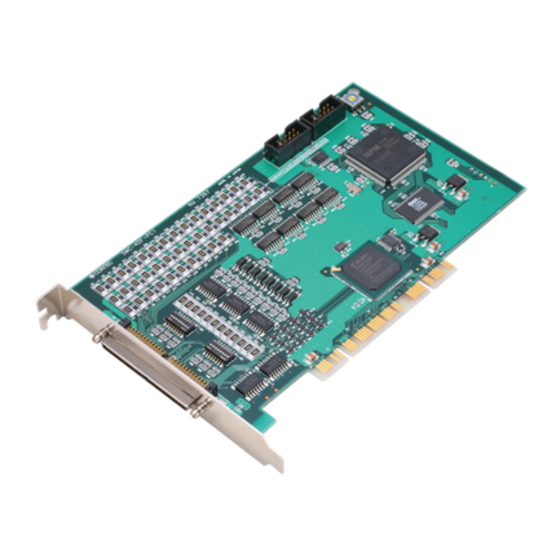
Summary of Contents for Contec SMC-4DF-PCI
- Page 1 PC-HELPER High-Speed Motion Control Board for PCI (4 axes) SMC-4DF-PCI (8 axes) SMC-8DF-PCI User’s Guide CONTEC CO.,LTD.
- Page 2 Check Your Package Thank you for purchasing the CONTEC product. The product consists of the items listed below. Check, with the following list, that your package is complete. If you discover damaged or missing items, contact your retailer. Product Configuration List Board (One of the following) [SMC-4DF-PCI or SMC-8DF-PCI] …1...
-
Page 3: Copyright
No part of this document may be copied or reproduced in any form by any means without prior written consent of CONTEC CO., LTD. CONTEC CO., LTD. makes no commitment to update or keep current the information contained in this document. The information in this document is subject to change without notice. -
Page 4: Table Of Contents
Using the Board under an OS Other than Windows ..............10 Step 1 Installing the Software ......................11 Which Driver to Use ........................11 Starting the Install Program....................... 11 Selecting API-SMC(WDM) ...................... 12 Executing the Installation ......................12 SMC-4DF-PCI, SMC-8DF-PCI... - Page 5 About each motor control operation....................43 PTP operation function ......................43 JOG operation function......................43 ORG operation function......................43 Linear interpolation ........................43 Circular interpolation......................... 43 S-curve acceleration/deceleration function ................43 Frame (bank) sequence operation function ................44 Synchronous control function....................45 SMC-4DF-PCI, SMC-8DF-PCI...
- Page 6 ABOUT SOFTWARE CD-ROM Directory Structure ......................55 About Software for Windows......................56 Accessing the Help File ......................56 Uninstalling the Driver library ....................57 ABOUT HARDWARE For detailed technical information ....................59 Hardware specification ........................59 Block Diagram..........................63 SMC-4DF-PCI, SMC-8DF-PCI...
- Page 7 SMC-4DF-PCI, SMC-8DF-PCI...
-
Page 8: Before Using The Product
- Capable of multi-axis independent control and pulse output up to 6.5Mpps SMC-4DF-PCI : Control for up to 4 axes and motor control pulse output up to 6.5Mpps are available. SMC-8DF-PCI : Control for up to 8 axes and motor control pulse output up to 6.5Mpps are available. -
Page 9: About Migration From The Existing Products
“Migration guide” which summarizes migration methods and differences about initial settings and API function units is provided. Please use the guide for your reference. ”Migration guide” can be downloaded from the download library of CONTEC’s Web site (http://www.contec.com/download) SMC-4DF-PCI, SMC-8DF-PCI... -
Page 10: Support Software
Visual Basic, Visual C++, Visual C# You can download the updated version from the CONTEC’s Web site (http://www.contec.com/apipac/). For more details on the supported OS, applicable language and new information, please visit the CONTEC’s Web site. Cable & Connector (Option) Shielded Cable With Two 100pin Connector : PCB100PS-0.5 (0.5m) -
Page 11: Customer Support
You can download updated driver software and differential files as well as sample programs available in several languages. Note! For product information Contact your retailer if you have any technical question about a CONTEC product or need its price, delivery time, or estimate information. Limited Three-Years Warranty CONTEC products are warranted by CONTEC CO., LTD. -
Page 12: Safety Precautions
WARNING indicates a potentially hazardous situation which, if not avoided, could WARNING result in death or serious injury. CAUTION indicates a potentially hazardous situation which, if not avoided, may CAUTION result in minor or moderate injury or in property damage. SMC-4DF-PCI, SMC-8DF-PCI... -
Page 13: Handling Precautions
Even when using this product continuously, be sure to read the manual and understand the contents. Do not modify this product. CONTEC will bear no responsibility for any problems, etc., resulting from modifying this product. Regardless of the foregoing statements, CONTEC is not liable for any damages whatsoever (including damages for loss of business profits) arising out of the use or inability to use this CONTEC product or the information contained herein. -
Page 14: Environment
(3) Store the package at room temperature at a place free from direct sunlight, moisture, shock, vibration, magnetism, and static electricity. Disposal When disposing of the product, follow the disposal procedures stipulated under the relevant laws and municipal ordinances. SMC-4DF-PCI, SMC-8DF-PCI... - Page 15 1. Before Using the Product SMC-4DF-PCI, SMC-8DF-PCI...
-
Page 16: Setup
For setting up software other than API-PAC(W32), refer to the manual for that software. See also the following parts of this manual as required. This chapter Step 2 Setting the Hardware This chapter Step 3 Installing the Hardware Chapter 3 External Connection Chapter 6 About Hardware SMC-4DF-PCI, SMC-8DF-PCI... -
Page 17: Using The Board Under An Os Other Than Windows
Using the Board under an OS Other than Windows For using the board under an OS other than Windows, see the following parts of this manual. This chapter Step 2 Setting the Hardware Chapter 3 External Connection Chapter 6 About Hardware SMC-4DF-PCI, SMC-8DF-PCI... -
Page 18: Step 1 Installing The Software
If the panel does not appear, run (CD-ROM drive letter):\AUTORUN.exe. (3) Click on the [Install Development or Execution Environment] button. CAUTION Before installing the software in Windows XP, Server 2003, 2000, log in as a user with administrator privileges. SMC-4DF-PCI, SMC-8DF-PCI... -
Page 19: Selecting Api-Smc(Wdm)
Clicking the [API-SMC] button displays detailed information about API-SMC(WDM) and API-SMC(98/PC). Executing the Installation (1) Follow the on-screen instructions to proceed to install. (2) After finishing installing, Readme file is displayed. You have now finished installing the software. SMC-4DF-PCI, SMC-8DF-PCI... -
Page 20: Step 2 Setting The Hardware
Note that the switch setting shown below is the factory default. - Synchronization signal - Terminator setting connector (CN2, CN3) (SW2 - SW5) BOARD ID - Board ID setting - Interface connector switch (CNA, CNB) BOARD ID Figure 2.1. Component Locations < SMC-8DF-PCI > SMC-4DF-PCI, SMC-8DF-PCI... - Page 21 2. Setup - Synchronization signal connector (CN2, CN3) - Terminator setting (SW2 - SW3) BOARD ID - Board ID setting - Interface connector switch BOARD ID Figure 2.2. Component Locations < SMC-4DF-PCI > SMC-4DF-PCI, SMC-8DF-PCI...
-
Page 22: Setting The Board Id
Select whether to insert the terminator depending on the system to be used. Setup Method To select whether to insert the terminator, use the DIP switches (SMC-4DF-PCI : SW2 and SW3, SMC-8DF-PCI : SW2 - SW5) on the board. Set each SW according to the figure shown below. -
Page 23: Plugging The Board
Make sure that your PC or expansion unit can supply ample power to all the boards installed. Insufficiently energized boards could malfunction, overheat, or cause a failure. Power supply from the PCI bus slot at +5V is required. SMC-4DF-PCI, SMC-8DF-PCI... -
Page 24: Step 3 Installing The Hardware
In this case, you must check the resource settings. When Using API-SMC(WDM) (1) The “Found New Hardware Wizard” will be started. Select “Install from a list or specific location[Advanced]”, then click on the [Next] button. SMC-4DF-PCI, SMC-8DF-PCI... - Page 25 (2) Specify that folder on the CD-ROM which contains the setup information (INF) file to register the board. * The name of the board you have just added is displayed. - SMC-4DF-PCI - SMC-8DF-PCI Source folder The setup information (INF) file is contained in the following folder on the bundled CD-ROM. \INF\WDM\SMC \INF\WDM\SMC You have now finished installing the hardware.
-
Page 26: Step 4 Initializing The Software
- SMC-4DF-PCI - SMC-8DF-PCI (2) The installed hardware appears under the CONTEC Devices node. Open the CONTEC Devices node and select the device you want to setup (the device name should appear highlighted). Click [Properties]. SMC-4DF-PCI, SMC-8DF-PCI... - Page 27 * The name of the board you have just added is displayed. - SMC-4DF-PCI - SMC-8DF-PCI The initial device name that appears is a default value. You can use this default name if you wish. Make sure that you do not use the same name for more than one device.
-
Page 28: Step 5 Checking Operations With The Diagnosis Program
For direct connection to the board, see Chapter 3 “External Connection”. Connection diagram The following connection diagrams show connections using the dedicated screw terminal CCB-SMC2. <Pulse output> CCB-SMC2 Driver Unit CCW+ CCW+ CCW- CCW- Figure 2.5. Connection diagram < 1 / 2 > SMC-4DF-PCI, SMC-8DF-PCI... - Page 29 2. Setup <Limit input> CCB-SMC2 +LIM +LIM +LIM -LIM -LIM -LIM +12V - +24VDC Figure 2.5. Connection diagram < 2 / 2 > SMC-4DF-PCI, SMC-8DF-PCI...
-
Page 30: Using The Diagnosis Program
Click the [Diagnosis] button on the device property page to start the diagnosis program. * The name of the board you have just added is displayed. - SMC-4DF-PCI - SMC-8DF-PCI Checking for motor control (1) Select the name of the axis you want to diagnose, then click on the [Execute Initial Setup Utility] button to execute Quick Check. - Page 31 (2) Check/mask each signal. When the alarm (ALM/ES) is ON or each limit (+LIM, -LIM) is ON, the motor does not operate in that direction. In this case, check the connection of the signal or mask it. SMC-4DF-PCI, SMC-8DF-PCI...
- Page 32 2. Setup (3) Simple operation is performed. SMC-4DF-PCI, SMC-8DF-PCI...
-
Page 33: Setup Troubleshooting
Refer to the source code for the sample programs. The OS does not boot correctly or does not detect the device correctly. Refer to the "Troubleshooting" section of API-SMC(WDM) HELP. If your problem cannot be resolved Contact your retailer. SMC-4DF-PCI, SMC-8DF-PCI... -
Page 34: External Connection
HDRA-EC100LFDT+ [mfd.by HONDA TSUSHIN KOGYO CO., LTD] equivalent Compatible connector HDRA-E100MA1[mfd.by HONDA TSUSHIN KOGYO CO., LTD] * Please refer to chapter 1 for more information on the supported cable and accessories. Figure 3.2. Interface Connector Shape < SMC-4DF-PCI > SMC-4DF-PCI, SMC-8DF-PCI... -
Page 35: Connector Pin Assignment
: OUT3 axis1 : OUT2 axis3 : OUT2 axis1 : OUT1 axis3 : OUT1 axis1 : DIR+/CCW+ axis3 : DIR+/CCW+ axis1 : DIR-/CCW- axis3 : DIR-/CCW- axis1 : OUT+/CW+ axis3 : OUT+/CW+ axis1 : OUT-/CW- axis3 : OUT-/CW- SMC-4DF-PCI, SMC-8DF-PCI... - Page 36 DIR-/CCW- Direction/CCW output- +LIM Positive-direction limit OUT+/CW+ Pulse/CW output+ -LIM Negative-direction limit OUT-/CW- Pulse/CW output- Power ground input (common to internal Encoder phaseA input+ GND) Encoder phaseA input- Figure 3.3. Pin Assignments of Interface Connector (CNB) < SMC-8DF-PCI > SMC-4DF-PCI, SMC-8DF-PCI...
- Page 37 : IN6/CLR axis6 : IN5/PCS axis4 : IN5/PCS axis6 : IN4/LTC axis4 : IN4/LTC axis6 : IN3/SD axis4 : IN3/SD axis6 : IN2/INP axis4 : IN2/INP axis6 : IN1/ALM axis4 : IN1/ALM axis6 : P-COM axis4 : P-COM SMC-4DF-PCI, SMC-8DF-PCI...
- Page 38 DIR-/CCW- Direction/CCW output- +LIM Positive-direction limit OUT+/CW+ Pulse/CW output+ -LIM Negative-direction limit OUT-/CW- Pulse/CW output- Power ground input (common to internal Encoder phaseA input+ GND) Encoder phaseA input- Figure 3.4. Pin Assignments of Interface Connector (CNA) < SMC-8DF-PCI > SMC-4DF-PCI, SMC-8DF-PCI...
- Page 39 3. External Connection Pin Assignments of Interface Connector < SMC-4DF-PCI > axis0 : P-COM axis2 : P-COM axis0 : IN1/ALM axis2 : IN1/ALM axis0 : I N2/INP axis2 : IN2/INP axis0 : IN3/SD axis2 : IN3/SD axis0 : IN4/LTC axis2 : IN4/LTC...
- Page 40 DIR-/CCW- Direction/CCW output- +LIM Positive-direction limit OUT+/CW+ Pulse/CW output+ -LIM Negative-direction limit OUT-/CW- Pulse/CW output- Power ground input (common to internal Encoder phaseA input+ GND) Encoder phaseA input- Figure 3.5. Pin Assignments of Interface Connector < SMC-4DF-PCI > SMC-4DF-PCI, SMC-8DF-PCI...
-
Page 41: Connecting Output Signals
Figure 3.6. Pulse output circuit (Connection with the differential input) Connection with the opto-coupler input (When the driver unit guarantees the connection with the differential output) Driver Unit Board AM26LS31 or equivalence to it CCW+ CCW- Figure 3.7. Pulse output circuit (connection with the opto-coupler input) SMC-4DF-PCI, SMC-8DF-PCI... - Page 42 In addition, please insert a current-limiting resistor according to the allowable current and drive current of the connected input circuit. To prevent the circuit from malfunctioning due to noise, wire it as far away from other signal lines and noise sources as possible. SMC-4DF-PCI, SMC-8DF-PCI...
-
Page 43: Control Signal/General-Purpose Signal Output Circuit (Out1 - Out3, Erc, Cp1, Cp2)
Output circuit of each output signal on this product is illustrated below. The signal output is an open-collector output. A ground wire must therefore be connected for driving. Board Driver Unit OUT1 - OUT3 +12 - +24VDC Figure 3.10. Output circuit SMC-4DF-PCI, SMC-8DF-PCI... -
Page 44: Connecting Input Signals
Connection with the differential output Board Driver Unit AM26LS31 or equivalence to it Phase A+ Phase A- AM26LS31 or equivalence to it Phase B+ Phase B- AM26LS31 or equivalence to it Phase Z+ Phase Z- Figure 3.11. Encoder input circuit SMC-4DF-PCI, SMC-8DF-PCI... - Page 45 Board Driver Unit TTL level AM26LS31 or output equivalence to it Phase A+ TTL level AM26LS31 or output equivalence to it Phase B+ TTL level AM26LS31 or output equivalence to it Phase Z+ Figure 3.12. Encoder input circuit SMC-4DF-PCI, SMC-8DF-PCI...
- Page 46 Restrict the use of cables to 10m for the line driver output, 3m for the open-collector output, and 1.5m for the TTL level output. To prevent the circuit from malfunctioning due to noise, wire it as far away from other signal lines and noise sources as possible. SMC-4DF-PCI, SMC-8DF-PCI...
-
Page 47: Limit Input/General-Purpose Input/Control Input Circuit (In1 - In7, +Lim, -Lim, Org)
+12 - +24 V. External Board Device External Plus Power Supply Common +12 - +24VDC Input Swich Photocoupler Input Swich Photocoupler * Input pin is IN1 - IN7, +LIM, -LIM, ORG. Figure 3.14. Limit input/general-purpose input/control input circuit SMC-4DF-PCI, SMC-8DF-PCI... -
Page 48: Connection Examples
(40) OUT2 (65) /ALM-RST (44) (18) (15) OUT3 (66) /CLR (14) CW+ (61) PLUS (60) /PLUS CCW+ (63) SIGN (11) CCW- (62) /SIGN (12) Figure 3.15. Example of Connection to driver unit (Σ II Series) for Servo motor SMC-4DF-PCI, SMC-8DF-PCI... -
Page 49: Surge Voltage Countermeasures
OUT 1 - 3 Surge current Resistor prevention resistor Figure 3.16. Surge Voltage Countermeasure CAUTION In order for a protection circuit to operate effectively, it must be connected within 50 cm of a load and a contact point. SMC-4DF-PCI, SMC-8DF-PCI... -
Page 50: Functions
This product has the S-curve acceleration/deceleration function in addition to the linear acceleration/deceleration function. The S-curve acceleration/deceleration function reduces acceleration when starting and stopping accelerating/decelerating the motor, thereby suppressing the vibration generated at the start and end of motion. SMC-4DF-PCI, SMC-8DF-PCI... -
Page 51: Frame (Bank) Sequence Operation Function
600µsec Pentium III 800MHz / i815 / 8 axes 800µsec Table 4.2. When CONTEC's expansion unit ECH(PCI)BE-H2B, ECH(PCI)BE-H4B, ECH(PCI)BE-F2B, ECH(PCI)BE-F4B and ECH(PCI)BE-H4A are used CPU / Chip Set / Number of operation axes Time of a frame (bank) sequence (Min.) Core 2 Duo E6300 / Q965 / 1 axis 200µsec... -
Page 52: Synchronous Control Function
This product makes it possible for synchronization control up to 128 axes (SMC-8DF-PCI : 16 pieces in use) by connecting to SMC-4DF-PCI or SMC-8DF-PCI with a dedicated synchronization control cable. Synchronization is the function that makes the motors start operation at the identical timing or, if any of the motors is stopped with an alarm (abnormal stop), stops all the relevant axes at once. -
Page 53: Meanings Of Signals
The logical direction can be set by software. ORG (origin input) ORG is the switch input to detect the origin to be set as the base point for each operation. The logical direction can be set by software. SMC-4DF-PCI, SMC-8DF-PCI... -
Page 54: Encoder Input Signal
A count cannot be performed properly, if Phase A (UP) pulse and Phase B (DOWN) pulse are generated at the same time. U : Up Count D : Down Count Figure 4.3. Sample Count for Single-phase Input Setting SMC-4DF-PCI, SMC-8DF-PCI... -
Page 55: Pulse Output Signal
The CW and CCW directions are indicated by the signal status of DIR (direction output). Note that the DIR signal is valid only when the OUT signal is active. When positive direction operates When negative direction operates Figure 4.5. Specification for Output Pulse in Common Pulsing Method SMC-4DF-PCI, SMC-8DF-PCI... -
Page 56: General-Purpose Input Signals
INP is the signal to detect the positioning completion signal from the motor driver unit. The input logic can be changed by software. SD (deceleration (decelerated stop) input) SD is a signal to detect the position at which to start deceleration. The input logic can be changed by software. SMC-4DF-PCI, SMC-8DF-PCI... -
Page 57: General-Purpose Output Signals
P.COM is the plus common signal for limit input signals (+LIM, -LIM, SD, ORG) and general-purpose input/output signals (IN1 - IN7, OUT1 - OUT3). GND (Ground) GND is the ground line for the general-purpose output signals (OUT1 - OUT3). SMC-4DF-PCI, SMC-8DF-PCI... -
Page 58: Connecting The Synchronization Control Connectors
Use a synchronization signal cable to connect the CN2 of a smaller ID board to the CN3 of the board with a greater board ID number. ID = 0 ID = 1 ID = 2 Figure 4.7. Connection method of a cable SMC-4DF-PCI, SMC-8DF-PCI... - Page 59 CAUTION Connectors for synchronization signals control of this product (CN2, CN3) are dedicated for SMC-4DF-PCI, SMC-8DF-PCI. Please do not connect this synchronization cable with products other than SMC-4DF-PCI and SMC-8DF-PCI. Please make up synchronization groups from axis 0 or axis 4.
-
Page 60: Motion Control System
When a table is used in the system, the sensor is bundled with the table. For a self-made system, use commercially available switches. DC Power supply Power supply to the CCB-SMC2. Use a 12 - 24-VDC power supply. (Power supply maker) SMC-4DF-PCI, SMC-8DF-PCI... - Page 61 4. Functions SMC-4DF-PCI, SMC-8DF-PCI...
-
Page 62: About Software
|––Win95 |––linux Driver file for Linux |––cnt |––dio |––…… | ––Readme Readme file for each driver | ––Release Driver file on each API-TOOL |––API_NT (For creation of a user-specific install program) |––API_W95 |––UsersGuide Hardware User's Guide (PDF files) SMC-4DF-PCI, SMC-8DF-PCI... -
Page 63: About Software For Windows
Reference”, “Sample Programs”, and “Q&A”. Use them for program development and troubleshooting. Accessing the Help File (1) Click on the [Start] button on the Windows taskbar. (2) From the Start Menu, select “Programs” – “CONTEC API-PAC(W32)” - “SMC” - “API-SMC-D HELP” to display help information. SMC-4DF-PCI, SMC-8DF-PCI... -
Page 64: Uninstalling The Driver Library
(2) Double-click on “Change/Remove Programs” in the Control Panel. (3) Double-click on “Change or Remove Programs” in the Control Panel. Select “CONTEC API-SMC(WDM) driver” from the application list displayed, then click on the [Change/Remove] button. Follow the on-screen instructions to uninstall the function libraries. - Page 65 5. About Software SMC-4DF-PCI, SMC-8DF-PCI...
-
Page 66: About Hardware
This chapter provides hardware specifications and hardware-related supplementary information. For detailed technical information For further detailed technical information (“Technical Reference” including the information such as an I/O map, configuration register, etc.), visit the Contec's web site (http://www.contec.com/support/) to call for it. Hardware specification Tables 6.1 - 6.6 list the hardware specifications of the board. - Page 67 Opto-coupler input (corresponding to current sink output) Input type Response time (Max.) 200 µ sec Input resistance 4.7k Ω Input ON current 2.0mA or more Input OFF current 0.16mA or less External circuit power 12V - 24VDC(±10%) supply SMC-4DF-PCI, SMC-8DF-PCI...
- Page 68 90 º C phase difference pulse (lead/lag pulse) Output form Un-isolated differential line driver output Device used AM26LS31(T.I) or equivalence to it H level output voltage 2.5V - 5.25V L level output voltage 0V - 0.5V Rated output current (Max.) 20mA SMC-4DF-PCI, SMC-8DF-PCI...
- Page 69 (Enables selecting the positive/negative logic by using the Software) Response time (Max.) 10 µ sec (when using the loading on the input side 510 Ω , +24VDC) Rated output current (Max.) 100mA per 1ch, 300mA per 1axis Rated output withstanding 50VDC voltage (Max.) SMC-4DF-PCI, SMC-8DF-PCI...
-
Page 70: Block Diagram
Limit input Motor controller PCL6045B Driver Pulse output Encoder input Receiver Axis 7 Photo-coupler Limit input * Only SMC-8DF-PCI General-purpose Transistor output (Each axis 3ch) General-purpose Photo-coupler input (Each axis 7ch) Synchronization signal SMC-4DF-PCI SMC-8DF-PCI Figure 6.1. Block Diagram SMC-4DF-PCI, SMC-8DF-PCI... - Page 71 3-9-31, Himesato, Nishiyodogawa-ku, Osaka 555-0025, Japan Japanese http://www.contec.co.jp/ English http://www.contec.com/ Chinese http://www.contec.com.cn/ No part of this document may be copied or reproduced in any form by any means without prior written consent of CONTEC CO., LTD. [03092007] [03092007] Management No. A-51-318 Parts No. LYGQ961...
Need help?
Do you have a question about the SMC-4DF-PCI and is the answer not in the manual?
Questions and answers