
Related Manuals for Texas Instruments Stellaris MDL-BDC24


Summary of Contents for Texas Instruments Stellaris MDL-BDC24
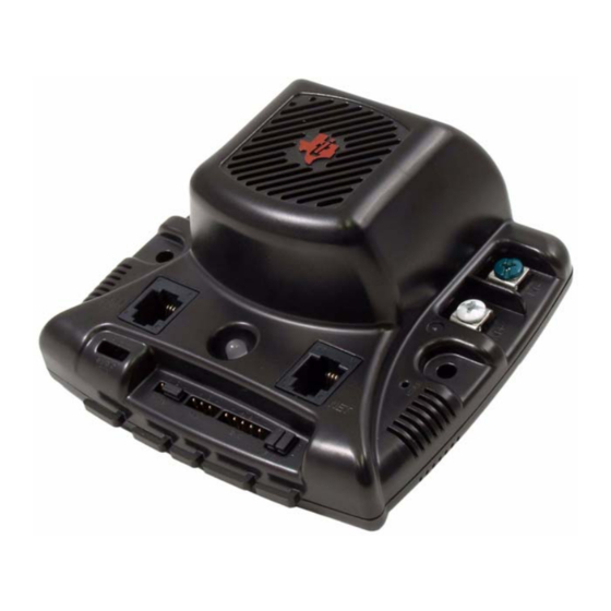
- Page 1 Stellaris® MDL-BDC24 Brushed DC Motor Control Module Getting Started Guide MDL-BDC24 - GSG-0 4 Co pyrigh t © 2 009– 201 1 Te xas In strumen ts...
- Page 2 Copyright Copyright © 2009–2011 Texas Instruments, Inc. All rights reserved. Stellaris and StellarisWare are registered trademarks of Texas Instruments. ARM and Thumb are registered trademarks, and Cortex is a trademark of ARM Limited. Other names and brands may be claimed as the property of others.
-
Page 3: Table Of Contents
Stellaris® Brushed DC Motor Control User’s Manual Table of Contents Chapter 1: Introduction to Jaguar ........................5 Features................................7 Differences between the MDL-BDC and MDL-BDC24 ..................8 Warnings................................8 Chapter 2: General Operation.......................... 9 Operating Modes .............................. 10 Fault Conditions ............................10 Coast/Brake Jumper ............................. - Page 4 January 5, 2011...
-
Page 5: Chapter 1: Introduction To Jaguar
C H A P T E R 1 Introduction to Jaguar Texas Instruments presents the next generation FIRST Robotics Competition (FRC) motor controller: the MDL-BDC24 brushed DC motor control (also known as Black Jaguar). The MDL-BDC24 builds on the success of the first-generation MDL-BDC (Gray Jaguar) by adding an RS232-to-CAN gateway and enhanced electrical performance. - Page 6 Introduction to Jaguar Figure 1-2. MDL-BDC24 Development Process Getting Started with Jaguar Read Jaguar GSG Introduction and General Operation Chapters Decision: Network Control using Servo/PWM or Network? Read Jaguar GSG Introduction to Servo/PWM Network Control Chapter Read Jaguar GSG Servo/PWM Control Chapter Decision:...
-
Page 7: Features
Getting Started Guide Features The Stellaris® Brushed DC Motor Control Module with CAN (MDL-BDC24) offers a variable speed control for 12 V and 24 V brushed DC motors at up to 40 A continuous current. The motor control module includes high performance Controller Area Network (CAN) connectivity and a rich set of control options and sensor interfaces, including analog and quadrature encoder interfaces. -
Page 8: Differences Between The Mdl-Bdc And Mdl-Bdc24
Introduction to Jaguar Differences between the MDL-BDC and MDL-BDC24 First generation Jaguar motor controls (MDL-BDC) have similar capabilities to the second generation Jaguar (MDL-BDC24). Functional differences are summarized in Table 1-1. Table 1-1. MDL-BDC and MDL-BDC24 Differences MDL-BDC (Gray) MDL-BDC24 (Black) Feature MDL-BDC MDL-BDC24... -
Page 9: Chapter 2: General Operation
C H A P T E R 2 General Operation This chapter describes the general operation of the MDL-BDC24 motor control module. Figure 2-1 shows the key features of the MDL-BDC24 motor control. Table 2-1 provides a key to the status LED. -
Page 10: Operating Modes
General Operation Table 2-2. Status LED (Continued) LED State Module Status Slow Flashing Red Fault condition Calibration Conditions Fast Flashing Red and Green Calibration mode active Fast Flashing Red and Yellow Calibration mode failure Fast Flashing Green and Yellow Calibration mode success Calibration mode reset to factory Slow Flashing Red and Green default settings success... -
Page 11: Coast/Brake Jumper
Getting Started Guide which is cleared instantly). A slow flashing Yellow LED indicates that the MDL-BDC24 is not receiving a valid control signal. Coast/Brake Jumper The coast/brake signal controls the dynamics of the drive signal to the motor. When set to brake, the MDL-BDC24 is able to achieve greater deceleration and holding torque because it decays regenerative current from the motor. - Page 12 General Operation January 5, 2011...
-
Page 13: Chapter 3: Servo/Pwm-Based Control
C H A P T E R 3 Servo/PWM-based Control The MDL-BDC and MDL-BDC24 both support speed and direction control through a servo-style PWM input. Figure 3-1 shows the servo-wiring details. Figure 3-1. Wiring for Servo-style PWM Control From Power Motor Distribution Module... - Page 14 Servo/PWM-based Control To calibrate the servo-style PWM input for a specific range, connect a PWM source, then: 1. Hold down the USER switch with a straightened paperclip for 5 seconds. 2. The LED flashes Red and Green to indicate Calibration mode. 3.
-
Page 15: Chapter 4: Introduction To Network-Based Control
C H A P T E R 4 Introduction to Network-Based Control Both MDL-BDC and MDL-BDC24 support CAN-based control, configuration and firmware updates. MDL-BDC24 also supports the same command set over RS232. Network Security and System Safety The factory default network protocol allows for very flexible control networks with all commands being accepted and executed without restriction. - Page 16 Introduction to Network-Based Control January 5, 2011...
-
Page 17: Chapter 5: Operation Using The Rs232 Interface
C H A P T E R 5 Operation using the RS232 Interface The MDL-BDC24 supports a full set of network control and configuration functions over a standard RS232C serial interface. The command protocol is essentially the same as the protocol used on the CAN interface allowing the MDL-BDC24 to automatically bridge all commands between the RS232 and CAN interfaces. - Page 18 Operation using the RS232 Interface Figure 5-2. BDC-COMM GUI Main Window January 5, 2011...
-
Page 19: Chapter 6: Firmware Update Using Bdc-Comm
C H A P T E R 6 Firmware Update Using BDC-COMM Firmware update capability allows Texas Instruments to provide new software, in binary format, that contains feature enhancements and bug fixes. Special firmware releases have been created for FRC 2010. Both MDL-BDC and MDL-BDC24 have firmware updates available. -
Page 20: Step 2: Run Bdc-Comm
Firmware Update Using BDC-COMM Step 2: Run BDC-COMM Run BDC-COMM.EXE. The LED on the Jaguar(s) should now be solid yellow indicating a valid network link. If the LED is not solid yellow, check all network connections as well as the BDC-COMM Com Port setting. A valid link must be established before proceeding to the next step. -
Page 21: Chapter 7: Closed-Loop Control Options
C H A P T E R 7 Closed-Loop Control Options A network-controlled Jaguar supports several types of closed-loop control through an internal PID controller. Constant-current control Position control using an encoder Position control using a potentiometer Speed control Only one mode can be used at a time. For each control mode, refer to API, VI, or tool documentation for information on which commands to use for configuration. -
Page 22: Constant Current Control
Closed-Loop Control Options Figure 7-1. Advanced Wiring Diagram Power In Motor Out (-) Supply / GND (-) Motor (+) Supply (+) Motor User switch sets CAN ID CAN cable to/from CAN cable to/from other devices other devices Normally-closed limit switches Reverse Limit H=Coast, L=Brake Forward Limit... -
Page 23: Position Control Using A Potentiometer
Getting Started Guide An edge on the Index (“I”) input resets the position counter to zero. The MDL-BDC and MDL-BDC24 modules support a wide range of shaft encoders. Encoder electrical parameters are detailed in the corresponding data sheets. If the P, I and D parameters are positive (or zero), the MDL-BDC and MDL-BDC24 modules expect that a forward condition (+ voltage on White terminal, - voltage on Green) generates increasing counts on the encoder interface. - Page 24 Closed-Loop Control Options January 5, 2011...
-
Page 25: Chapter 8: Operation Using The Can Interface
C H A P T E R 8 Operation Using the CAN Interface CAN Overview Controller Area Network (CAN) provides a powerful interface for controlling one or more Jaguar modules. Jaguar has a 6P6C socket and a 6P4C socket for daisy-chaining modules using Ω... -
Page 26: Control Options For Networked Jaguar Modules
Operation Using the CAN Interface Figure 8-1. CAN Network Topology Black Jaguar Jaguar or Black Jaguar Jaguar or Black Jaguar Connect to cRIO Serial Port Terminator 6P4C or 6P6C modular cable Additional Jaguars Serial to 6P6C cable Plug CAN cabling follows a daisy-chained topology using modular cable. Table 8-1 lists network parameters. - Page 27 Getting Started Guide LabView VI Java API C++ API Example source code for a host-based on a Stellaris Microcontroller can be found in StellarisWare® (\boards\rdk-bdc\bdc-ui) also available at www.luminarymicro.com/jaguar. January 5, 2011...
- Page 28 Operation Using the CAN Interface January 5, 2011...
-
Page 29: Appendix A: Jaguar Communication Cables
A P P E N D I X A Jaguar Communication Cables CAN Terminator Because the CAN signals operate at high bit rates (1 MBPS), a terminator is required at each end of the network. A simple network might work with a single terminator, but this is not recommended for normal use. -
Page 30: Can Cable Assembly
RS232 Cable CAN Cable Assembly Follow these steps to complete cable assembly (shown in Figure A-3): 1. Cut modular cable to length 2. Use the crimp to strip the outer jacket from each end of the cable. 3. Insert wires into the modular plug and load into crimper. 4. -
Page 31: Rs232 Cable Pin Assignments
Getting Started Guide 3. Insert remaining terminals into the DB9 receptacle. Pin numbers are indicated on the plastic connector body. – White/Pin 3 – Blue/Pin 2 – Yellow/Pin 5 4. Slide the back-shell over the connector, then insert the modular cable to complete the assembly. - Page 32 External References January 5, 2011...
- Page 33 IMPORTANT NOTICE Texas Instruments Incorporated and its subsidiaries (TI) reserve the right to make corrections, modifications, enhancements, improvements, and other changes to its products and services at any time and to discontinue any product or service without notice. Customers should obtain the latest relevant information before placing orders and should verify that such information is current and complete.
Need help?
Do you have a question about the Stellaris MDL-BDC24 and is the answer not in the manual?
Questions and answers