
Summary of Contents for Easson ES-12
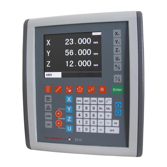
- Page 1 Always Committed to Quality, Technology & Innovation ES-12 Digital Readout System Operation Manual...
-
Page 2: Table Of Contents
Content Safety Notice ........I Specifications........II Installation ........II 1. Basic Functions ....... 01 2. Built in Calculator ......08 3. 199 Sub Datum Function ....12 4. REF Datum Memory ......20 5. LHOLE Function ......24 6. INCL Function ......... 28 7. - Page 3 Warning and key points Do not put the display near water or Install the display with double- Do not use damaged power patch plug oil etc, or it will be at the risk of and put the power cable near the heat screw bolt and fix it on a stable catching fire.
- Page 4 ** VERY IMPORTANT : SAFETY NOTICE ** ATTENTION: To avoid possible Electrical Shock !! The DRO's grounding must be connected to the earth terminal of a power socket / source which protected by an Earth Leakage Circuit Breaker. ** Install the Power Grounding as per shown in following diagrams. **...
- Page 5 SPECIFICATIONS SPECIFICATIONS : Operation Voltage: 115 / 230V AC Supply Voltage Fluctuation: Not to exceed +10% of the operating voltage Supply Frequency 50 - 60Hz Max Power Consumption 20 VA Operating Temperature 0 'C - 45 'C 32 'F - 113 'F Operating Relative Humidity <=95% (45 'C + 2 'C ) Storage Temperature...
- Page 6 POWER SUPPLY CONNECTION 2.2 POWER SUPPLY CONNECTION Before connecting the electrical supply to the DRO, please check the VOLTAGE SELECTOR switch to see if correctly main supply voltage selected or not. Check Figure below for the position of the switch. The PROTECTIVE EARTH CIRCUIT of the mains supply MUST BE CONNECTED to the earth grounding terminal of the DRO through the supply cord and connected through an earth cable as per shown in Page 1.
- Page 7 LINEAR TRANSDUCER CONNECTION 2.3 LINEAR TRANSDUCER CONNECTION Connection sockets as shown in Figure 2.3. The transducers are connected to the DRO with 9-pin DB Type connectors. Switch off the DRO before connecting or disconnecting the linear transducers. To fit the connectors into the appropriate socket on the back of the DRO, first align the connector and then push firmly in place.
- Page 8 Basic Functions Basic Fucntions BASIC - 1 -...
-
Page 9: Basic Functions
Basic Functions - Set display to ZERO Purpose : Set the current position for that axis to ZERO Example : To set the current X axis position to ZERO 12.345 0.000 25.000 25.000 Inch / Metric display conversion Purpose : Switches between Inch and Metric display Example 1 : Currently in Inch display, to swap to Metric display 1.0000 25.400... - Page 10 Basic Functions - Centre Find Purpose : ES-12 provides centre find function by halfing the current display coordinate, so that the zero position of the work piece is located at the centre of the work piece. Example : To set the current X axis zero position at the centre of the work piece Step 1 : Locate the edge finder at one end of the work piece, then zero the X axis.
- Page 11 Basic Functions - ABS/INC coordinate display Purpose : ES-12 provides two sets of basic coordinate display, they are ABS ( absolute ) and INC ( incremental ) displays. During machining operations, operator can store the work piece datum ( ZERO position ) in ABS...
- Page 12 ( such as cutting, facing and etc.. ). ES-12 provides the SPEED function to display the machine moving speed in mm/min in all selected axis. The SPEED display is filtered by an 0.25 sec display filter to provide stabilized speed display, to enable the operator to adjust the machine's power feed at a more easy and comfortable speed visualization.
- Page 13 ES-12 provides vibration filtering function to stabilize the digits display, it make the operator more comfortable during the position visualization. Filtering bandwidth parameter can be set in SETUP procedure to adopt the different condition of the machine.
- Page 14 Purpose : The Axes Summing function is a useful function for LATHE application. ES-12 provides the axes summing function for providing temporarily summing display of XZ and YZ axes, operator can swap back to the orginal displays ( X/Y/Z individual display with no summing of axes ) at any time they want.
- Page 15 Built in Calculator Calculator - 8 -...
-
Page 16: Built In Calculator
Function : Calculator is the most frequently use tool during the manual machining process. ES-12 provides a built-in calculator which can perform normal mathematical calculations such as add, substract, multiply, division and etc., it also provides useful trigonmetric calculations that are frequently used during machining process, such as SIN, COS, TAN, SQRT, and also their inverses, such as inv SIN, inv COS, inv TAN, SQUARE... - Page 17 Built in Calculator Example : To enter into calculator function 12.345 12.345 78.975 78.975 45.765 45.765 The operations of the DRO's built-in calculator is same as common commerically available calculator i.e. Basic mathematics - add ; substract : 78 + 9 - 11 = 76 12.345 12.345 78.975...
- Page 18 Built in Calculator i.e. Trigonometric calculation - inverse SIN : SIN 0.5 =30 12.345 12.345 78.975 78.975 45.765 45.765 0.0087265 Result transfer i.e. To move the tool at the X axis position : 105 X 1.035 = 108.675 12.345 12.345 78.975 78.975 45.765...
- Page 19 199 Subdatum Function ( sdm 2 ) Subdatum 2 ( sdm 1 ) Subdatum 1 ( sdm 3 ) Subdatum 3 ( ABS ) ( sdm 4 ) work piece datum Subdatum 4 - 12 -...
-
Page 20: Sub Datum Function
! ES-12 provides extra 199 subdatums ( sdm ) memory to overcome the above shortfalls of having only the ABS/INC coordinates, sdm function not just simply provide 199 set of extra INC coordinates, it is specially designed to provide very useful and convenience operations to operator for repeative batch machining. - Page 21 199 Subdatum Function Application example : To set up the following four subdatum zero ( SdM 1 to SdM 4 ) as follows, followings two methods can be used. 1. move the machine directly to required subdatum positions, then zero SdM display coordinate 2.
- Page 22 199 Subdatum Function set this point switch to sdm 1 to ZERO coordiante display 50.000 0.000 35.000 0.000 0.000 0.000 SDM 1 SDM 1 sdm 1 set up already Step 3: setup the subdatum point 2 ( sdm 2 ) locate the tool at subdatum point 2 ( sdm 2 ) X=50.000 , Y=-50.000...
- Page 23 199 Subdatum Function Step 5: setup the subdatum point 2 ( sdm 4 ) locate the tool at subdatum point 2 ( sdm 4 ) X=-50.000 , Y=35.000 switch to ABS coordinate display 0.000 -50.000 0.000 35.000 0.000 0.000 set this point switch to sdm 4 to ZERO coordiante display...
- Page 24 199 Subdatum Function The DRO's XY displays is now switched to refered to sdm 2 zeros switch to next ( UP ) sdm coordinate display -100.000 85.000 0.000 SDM 2 The DRO's XY displays is now switched to refered to sdm 1 zeros switch to next ( DOWN ) sdm coordinate display -100.000...
- Page 25 199 Subdatum Function Step 2: setup the subdatum point 1 ( sdm 1 ) -50.000 switch to sdm 1 -35.000 coordiante display 0.000 0.000 SDM 1 0.000 Notice : 0.000 SDM 1 when the coordinated is entered into the DRO, the displayed coordinate in the axis display shows a negative sign of your entered coordinate...
- Page 26 199 Subdatum Function All the four subdatum points have already been set up operator can press to directly switch to the required subdatum ( sdm ) coordinate The DRO's XY displays is Example : now switched to refered to ABS zeros switch to ABS coordinate display 50.000...
- Page 27 REF datum memory - 20 -...
-
Page 28: Ref Datum Memory
Operation : ES-12 provides one of the best and most easy to use REF datum memory function in this industry. There is no need to store the relative distance between the REF mark and your work piece datum,... - Page 29 REF datum memory function - FIND REF In all basic functions of this DRO, such as dimension prset, zeroing, center find and etc., the DRO will Function : automatically store the relative distance between the REF mark and the work piece datum ( ABS Zero position ), however, it is the most vital and basic that the DRO must know where the REF mark is located.
- Page 30 REF datum memory function - RECALL 0 Function : after the lost of work piece datum due to power failure or switch off of the counter, the work piece datum can be recovered by RECALL 0 function. Please notice that if the operator do not perform the REF FIND at least one time before the establish of the work piece datum ( ABS zero position ), the RECALL 0 will give an error work datum position.
- Page 31 LHOLE - tool positioning for the Line Holes - 24 -...
-
Page 32: Lhole Function
LHOLE - tool positioning for Line Holes ES-12 provides the LHOLE function for tool positioning for the holes drilling along a line, operator simply enter the machining parameters as per the step by step guide that shown on the DRO's message display, then the DRO will calculate all the holes position coordinate, and temporarily preset those holes' position to zero ( 0.000, 0.000 ). - Page 33 LHOLE - tool positioning for Line Holes Step 2 : enter Line angle ( LIN ANG ) Line angle ( LIN ANG ) = -30 degree enter Line angle ( LIN ANG ) next step L.HOLE L.HOLE 0.000 -30.000 LINE ANGLE LINE ANGLE LINE ANGLE ? LINE ANGLE ?
- Page 34 LHOLE - tool positioning for Line Holes move the machine to axes display = ( 0.000, 0.000 ) next Line Hole L.HOLE 0.000 0.000 0.000 XY=0: HOLE 2 HOLE 2 = Line Hole no. 2 move the machine to axes display = ( 0.000, 0.000 ) previous Line Hole L.HOLE...
- Page 35 INCL - Inclined angle tool positioning - 28 -...
-
Page 36: Incl Function
The only solution is to calculate the machining positions using mathermatical method. It is very time consuming ES-12 provides an very easy to use INCL function to help the operator to posit the tool along an inclined angle. - Page 37 INCL - Inclined angle tool positioning Operation procedure approx. 20 degree install the work piece onto an rotary table at approximately 20 degree as shown in the above diagram. Step 1 : select the XY plane as the work plane ( INCL-XY ) XY plane INCL.
- Page 38 INCL - Inclined angle tool positioning The DRO is now entered into the INCL machining function cycle the datuming of the work piece at an inclined angle of 20 degrees is an iterative process, operations are as follows : A ) ZERO the dial imdicator at one end of the work piece XY plane INCL machining mode display zero the X axis...
- Page 39 INCL - Inclined angle tool positioning Anytime the operator want to check or verify if the DRO's INCL calculation correct or not, or want to temporarily exit the INCL machining mode display ( swap back to normal XYZ display ), procedure are as follows : temporarily return to XYZ coordinate display...
- Page 40 PCD - tool positioning for Pitch Circle Diameter - 33 -...
-
Page 41: Pcd Function
PCD - tool positioning for Pitch Circle Diameter Function : ES-12 provides the PCD function for tool positioning for the drilling of the pitch holes along a Circle, operator simply enter the machining parameters as per the step by step guide that shown on the DRO's message display, then the DRO will calculate all the pitch holes position coordinate, and temporarily preset those holes' position to zero ( 0.000, 0.000 ). - Page 42 PCD - tool positioning for Pitch Circle Diameter Step 2 : Enter the Centre coordinate ( CENTRE ) centre coordinate ( CENTRE ) : X=0.000, Y=0.000 enter the CENTRE coordinate next step 0.000 0.000 0.000 0.000 CENTER CENTER CENTER CENTER Step 3 : Enter Diameter ( DIA ) Diameter ( DIA ) = 80.000mm 80.000...
- Page 43 PCD - tool positioning for Pitch Circle Diameter Step 6 : Enter the End Angle ( End. ANG ) End angle ( ENd. ANG ) = 300 degree enter the End angle ( ENd. ANG ) 0.000 300.000 END.ANG END.ANG END.
- Page 44 PCD - tool positioning for Pitch Circle Diameter Anytime the operator want to check or verify if the DRO's PCD calculation correct or not, or want to temporarily exit the PCD function cycle ( swap back to normal XYZ display ), procedure are as follows : temporarily return to presently in PCD cycle XYZ coordinate display...
- Page 45 tool positioning for ARC machining - 38 -...
-
Page 46: Arc Function
1) One Off Job 2) Only simple ARC surface or round corners to be machined. ARC function groups The ARC function of the ES-12 consists of only one program, this program have following two functions R function Simplified R function... - Page 47 The coordinate is a pair of unmber which specify a position. When using the ES-12's R function, it is necessary to enter the coordinates of ARC's center, start point, end point and etc.. to let the ES-12 knows the geometry of the ARC ro be machined.
- Page 48 The ES-12's R function allows operator to machine R in XY, XZ and YZ plane as per following picture shows. When only 2 axis ES-12 is used, the ES-12 can calculate all the ARC tool positions on XZ & YZ work plane and assist the operator to posit the tool to the ARC machining points by a simulated Z position, the simulated Z position is showed on the message display of the ES-12 which shows the Z dial setting of the machine.
- Page 49 ARC according to the current Z position. In case the Z position are out of the ARC's Z position range, an warning message [ r. OU LI] - R is outside the Z limit is displaying on the Z axis of the ES-12.
- Page 50 Operation Example In case 2 Axes ES-12 is used, we must first reset the Z Dial to simulate the initial Z position at the ARC's start point ** Posit the Tool at start point of the ARC to be machined ** Set the Z axis Dial to ZERO ( 0.00 )
- Page 51 R function Step 2 : enter the Centre's coordinate ( XZ CENTR ) centre coordinate ( XZ CENTR ) : X=20.000, Z=20.000 enter centre's coordinate ( XZ CENTR ) next step R FUNC 20.000 R FUNC 0.000 20.000 0.000 XZ CENTER XZ CENTER in case of 2X DRO, since there is no Z axis use Y axis to enter Z axis centre coordinate...
- Page 52 R function Step 5 : enter the End point's coordinate ( XZ ENd P ) End point's coordinate ( XZ ST. PT ) : X=40.000, Z=20.000 enter start point's coordinate ( XZ ENd P ) next step R FUNC 40.000 R FUNC 0.000 20.000...
- Page 53 R function - For 3 Axes ES-12 If 2 axes ES-12 is used, please skip this page and go to the next two pages to continue the R parameters entry. For 3 axes ES-12, all the ARC parameter have been completely entered into the ES-12, the ES-12 will entered into the three axes ARC machining mode as per follows.
- Page 54 R function - For 3 Axes ES-12 Anytime the operaor want to check or verify if the DRO's ARC calculation correct or not, or want to temporarily exit the ARC function cycle ( swap to normal XYZ display ). Operation proceduer are as follows :...
- Page 55 R function - For 2 Axes ES-12 The following procedure are for 2 axes ES-12, not valid for 3 axis ES-12. Step 8: enter the Z increment per step machining This DRO provides two options on the Z increment per UP or DOWN key press, Operator can enter their selection in the R.
- Page 56 R function - For 2 Axes ES-12 Two Axes ARC machining mode operation : During the XZ and YZ plane R machining, it is necessary to accurately posit the Z axis to obtain a precise Z position. However, there is no Z axis in two axis DRO. Therefore in order to guide the operator easily posit the Z axis during the ARC machining.
- Page 57 R function - For 2 Axes ES-12 Anytime the operaor want to check or verify if the DRO's ARC calculation correct or not, or want to temporarily exit the ARC function cycle ( swap to normal XYZ display ). Operation proceduer are as follows :...
- Page 58 R function - XY plane ARC Example : X (+positive direction) Y (+positive direction) To machine an XY plane R as per shown in digram below Z (+positive direction) Following machining parameters have to enter into the DRO Start point ( 20, 0 ) Datum 1.
- Page 59 R function - XY plane ARC Step 2 : enter the Centre's coordinate ( XY CENTR ) centre coordinate ( CENTRE ) : X=20.000, Y=20.000 enter centre's coordinate ( XY CENTRE ) next step R FUNC 20.000 R FUNC 0.000 20.000 0.000 CENTER...
- Page 60 R function - XY plane ARC Step 5 : enter the End point's coordinate ( ENd. PT ) End point's coordinate ( End. PT ) : X=40.000, Y=20.000 enter start point's coordinate ( ENd. PT ) next step R FUNC R FUNC 0.000 40.000...
- Page 61 R function - XY plane ARC Step 8 : enter Max. Cut between interpolated points ( MAX CUT ) MAX CUT = 0.3mm R R R R enter the Maximum Cut ( MAX CUT ) R FUNC R FUNC 0.000 0.300 MAX.
- Page 62 R function - XY plane ARC Anytime the operaor want to check or verify if the DRO's ARC calculation correct or not, or want to temporarily exit the ARC function cycle ( swap to normal XYZ display ). Operation proceduer are as follows : temporarily return to presently in ARC cycle XYZ coordinate display...
- Page 63 Simplified R function - 56 -...
-
Page 64: Simplified R Function
ARCs, operator jusr select the type of R they needed to machine, input the Radius, tool dia, and ( for the 2 axes ES-12, the Z axis increment per machining step ), then they can start the R machining right away. - Page 65 ARC according to the current Z position. In case the Z position are out of the ARC's Z position range, an warning message [ r. OU LI] - R is outside the Z limit is displaying on the Z axis of the ES-12.
- Page 66 Tool Diameter = 6.0mm R=200mm Z (+positive direction) R=200 Operation procedure Because The ES-12's XZ/YZ can only machine an ARC which have less than 90 degree, therefore, it is necessary to divide this arc machining into two parts Second Part...
- Page 67 Simplified R Function Step 2 : select preser R type ( TYPE 1 - 8 ) For the first part, select preset R type 2 ( TYPE = 2 ) select R type ( TYPE 1-8 ) next step SIM. R SIM.
- Page 68 Simplified R Function - For 3 Axes ES-12 If 2 axes ES-12 is used, please skip this page and go to the next two pages to continue the R parameters entry. For 3 axes ES-12, all the ARC parameter have been completely entered into the ES-12, the ES-12 will entered into the three axes ARC machining mode as per follows.
- Page 69 Simplified R Function - For 3 Axes ES-12 Anytime the operaor want to check or verify if the ES-12's ARC calculation correct or not, or want to temporarily exit the ARC function cycle ( swap to normal XYZ display ). Operation proceduer are as follows :...
- Page 70 Simplified R Function - For 2 Axes DRO The following procedure are for 2 axes DRO, not valid for 3 axis DRO. Step 5: enter the Z increment per step machining This DRO provides two options on the Z increment per UP or DOWN key press, Operator can enter their selection in the R.
- Page 71 Simplified R Function - For 2 Axes DRO Two Axes ARC machining mode operation : During the XZ and YZ plane R machining, it is necessary to accurately posit the Z axis to obtain a precise Z position. However, there is no Z axis in two axis DRO. Therefore in order to guide the operator easily posit the Z axis during the ARC machining.
- Page 72 Simplified R Function - For 2 Axes DRO Anytime the operaor want to check or verify if the DRO's ARC calculation correct or not, or want to temporarily exit the ARC function cycle ( swap to normal XYZ display ). Operation proceduer are as follows : temporarily return to presently in ARC cycle XYZ coordinate display...
- Page 73 Shrinkage Calculation L X 1.005 - 66 -...
-
Page 74: Shrinkage Calculation Function
3) If any mistake happen, it is quite a big cost to fix especially after the mould hardened. ES-12 provides a practical Shrinkage calculation function to assist the mould maker to calcuate the reduced or expaned dimension, and also allow the mould maker to verify the expaned / reduced dimension very very easily. - Page 75 Shrinkage Calculation 2. Shrinkage Calculations ES-12 provides a very easy-to-use shrinkage calculation function of which allow the operator to calculate the expanded or reduced dimension very easily. It is virtually not possible to have a mould drawing that have 100% completed and corrected expanded or reduced dimensions.
- Page 76 "expanded" or "reduced" by the ratio of shrink factor. Example : To compensate by Expand, so that the DRO's To remind the operator that the ES-12 is in actual displayed dimension are expanded Shrinkage Compensation mode, the message display will displaying : by the ratio of the shrink factor.
- Page 77 Shrinkage Calculation To cancel the shrinkage compensation mode display, press to return to normal dimenson display normal actual dimension currently in shrinkage display compensation display return to normal display 100.500 100.000 100.500 100.000 100.500 100.000 - SHRINK. - 70 -...
- Page 78 Operation procedure 1. Enter the Shrink Factor into the ES-12, in this example, the ABS plastic is used of which the shrink factor is 1.005 press to enter the shrink factor 123.450...
- Page 79 Shrinkage Calculation During the machining, operator can return the normal dimension to verify if the machining properly calculated or not . To cancel the shrinkage compensation mode display, press to return to normal dimenson display currently in shrinkage normal actual dimension compensation display display return to normal display...
- Page 80 Application supplement for LATHE This supplementary chapter of the manual is only valid for the setting of DRO TYPE = LATHE in the SETUP menu. This is an supplementary chapter to the normal operation manual, it gives more realistic operational examples for the DRO operation for LATHE application.
- Page 81 Lathe application - Axes notation and common practise Function : Since the structure of Lathe machine and also the machining process in lathe is very different from common vertical or horizontal machines like milling, boring or drilling machines. The digram on the Left showing a very typical installation of DRO in lathe and showing the name of the axes.
- Page 82 Basic Functions - Dimension Preset Purpose : Set the current position for that axis to an entered dimension Example : To set the current X axis position to be 45.800mm 0.000 45.80 0.000 0.000 0.000 0.000 Application tips for lathe : The diemension preset function provides a very convenience way to monitor your cross feed in lathe maching.
- Page 83 Basic Functions - 199 tools datum memory Purpose : This DRO offer 199 tools memory, it is offered as a supplement of ABS/INC coordinates. For the lathe that have a high repeatability tool turret, this function provides a very quick ways to memory the tool tips offset, so that the operator don't have to datum the tool tips position whenever tool change is made.
- Page 84 INCL function - To swing the tool turret on the cross slide for conical machining To machine a conical work piece as per the diagram shown, it is the most basic that we have to swing the cross slide of the tool turret accurately at the incline angle that we have to machine. Most of the tool turret on the lathe have an angular dial allow the operator to swing the tool turret to the angle that required.
- Page 85 INCL function - To swing the tool turret on the cross slide for conical machining Step 2 : Enter into the INCL functon enter incline angle ( INCL ANG ) enter to the INCL function INCL. 56.785 0.000 45.675 12.345 INCL.
- Page 86 INCL function - To swing the tool turret on the cross slide for conical machining Step 4 : place the dial indicator against the bar, and ZERO both the DROs and the dial indicator XY plane INCL machining zero the Y axis mode display to redatum the Y axis...
- Page 87 INCL function - To swing the tool turret on the cross slide for conical machining Step 7 : Move the lathe's cross slide along X axis until the X axis DRO display = 0.000 INCL. 0.000 49.985 0.000 X=0 ANG-20.00 move lathe's cross slide until X axis display = 0.000 Step 8 : Swing the tool turret until the dial indicator pointing to ZERO...
- Page 88 INCL function - cone measurement Example : The INCL function of this DRO can be used in making the measurement of a conical work piece as per the diagram shown. Normally, the tool turret of the cross slide of the lathe can be swing to a inclined angle for conical machining, the angular alignment of the tool turret have been demonstarted in the other chapter of...
- Page 89 INCL function - cone measurement Step 3 : enter the incline angle ( INCL ANG ) Conical angle ( INCL ANG ) = -20 degree ( counter clockwise ) enter incline angle ( INCL ANG ) INCL. INCL. 0.000 -20.000 INCL.
- Page 90 INCL function - cone measurement Anytime the operator want to check or verify if the DRO's INCL calculation correct or not, or want to temporarily exit the INCL machining mode display ( swap back to normal XYZ display ), procedure are as follows : temporarily return to presently in INCL cycle...
-
Page 91: Parameters Setup
Parameter Setup SET UP - B. 1 -... - Page 92 Operating Procedure : 1) Switch off the ES-12 2) Switch on the ES-12, after switching on, with the software version no " VER. X-? " showing in the message window, press the number "8" key to enter the parameter reset function.
- Page 93 Parameters Setup Procedure - Introduction B) Parameters Setup Each ES-12 is configured as it leaves the factory, however, in order to enable each ES-12 to be individually set up for particular machine and application, following SETUP procedure is used. The SETUP procedure is written in a menu mode which enable you to using the pressing "UP" or "DOWN"...
- Page 94 Z axis dial increment of the milling machine. This paameter is used only for the two axes ES-12 which intent to use the ARC or R function for XZ/YZ plane arc. This parameter allows an two axis DRO to silmulate the Z axis movement for ARC or R machining function.
- Page 95 MESSAGE window, press the "ent" key to enter into the SETUP function. 1) Switch off the ES-12. 2) Switch on the ES-12, after switching on with the software version no. "VER. X - ?" in the message window, press "ent" key to enter the parameter SETUP function.
- Page 96 Parameters Setup Procedure - DRO TYPE The ES-12's software is all-in-one software which can config the ES-12 to provide professional DRO functions for one of the following applications, the talbe below listing out all the DRO functions available for different DRO TYPEs.
- Page 97 Parameters Setup Procedure - LANGUAGE To make the ES-12 more user friendly to the operator in different countries in the world, the message display of this DRO can be configured to display messages in one of the following languages. Press to select the "LANGUAGE"...
- Page 98 ARC, R, ZX/ZY/UX/UY axes summation and INCL. If the operator do not specify the number of axes in the DRO correctly, he will find that the ES-12's display axes are either the axis is not count ( display ) at all or the DRO functions not work properly.
- Page 99 Parameters Setup Procedure - DIRECTN DIRECTN menu is designed to allow user to swap the transducer ( linear scale or encoder ) counting direction. The count direction of the transducer are specified by '0' or '1' : '0' - DRO perform normal direct counting of the transducer. ( POSITIVE ) '1' - DRO will reverse the natural counting of the transducer.
- Page 100 0.005mm or 0.001mm resolution. Mixed resolutions display ( i.e. X axis in 0.005mm, Y axis in 0.001mm resolution is allowed in the ES-12 ). All DRO functions can work properly under the mixed resolutions display.
- Page 101 Parameters Setup Procedure - RAD/DIA RAD/DIA menu is designed to allow operator to select the diemension display in Radius ( nromal display ) or Diameteral ( 2X the real dimension ) display. This feature is very useful for lathe application. All axes in the DRO can be configrured to DIA ( 2X ) display.
- Page 102 Parameters Setup Procedure - LIN COMP LIN COMP menu is designed to allow user to enter the Linear Compensation value of each axis. The entered value must be in PPM ( Parts Per Million ). If the non-linear error compensation is in active, the Linear Compensation will not be effective any more.
- Page 103 Parameters Setup Procedure - NL ERROR NL ERROR menu is designed to allow user to enter the Non Linear Error Compensation value into the DRO, so that the DRO can compensate virtually all type of error in the machine. With DRO's non linear error compensation function, as long as the position repeatability of the machine is good, it can greatly improve the machine accuracy.
- Page 104 Parameters Setup Procedure - NL ERROR select the Axis select the FIND REF ( find ref mark ) FIND REF SEL AXIS Let's take X as an example select the X axis 0.000 SEL AXIS X REF after the display digits start run, move the machine across the ref mark of the scale until the digits move the move to X = 0.000, display start run.
- Page 105 Parameters Setup Procedure - NL ERROR Using a dial indicator to locate the most negative position of the step guage, zero the dial indicator at this position, record down this position as the CP . START position. Because the CP . START position always at the most negative position of the machine, therefore, it should always a NEGATIVE value...
- Page 106 "ent" once to enter to the SETUP function 8888.8888 8888.8888 8888.8888 8888.8888 SET UP . EASSON after entered into SETUP NL ERROR means Non to enter into function, press the "DOWN" Linear Error Compensatin Non Linear Error button until "NL ERROR"...
- Page 107 Parameters Setup Procedure - NL ERROR enter the CP . START 0.000 -115.875 0.000 0.000 CP . START CP . START enter CP . PITCH next step 0.000 25.000 0.000 0.000 CP . PITCH CP . PITCH enter CP . STEP next step CP .
- Page 108 Parameters Setup Procedure - NL ERROR Non Linear Error Compensation after all measured values selection done, Value input completed entered into the DRO, go to next menu press "ent" to exit the NL ERROR function. NL ERROR - B. 18 -...
- Page 109 Z DIAL menu is designed to allow user to specifies the Z axis machine increment per dial turn. This his paameter is used only for the two axes ES-12 which intent to use the ARC or R function for XZ/YZ plane arc.
- Page 110 Z DIAL menu is designed to allow user to specifies the Z axis machine increment per line mark of the Z Dial. This his paameter is used only for the two axes ES-12 which intent to use the ARC or R function for XZ/YZ plane arc.
- Page 111 Parameters Setup Procedure - R MODE R MODE menu is designed to allow user to specifies the Z axis interoplation method during the ARC or R function. This DRO can offer "MAX CUT" or "Z STEP" for choices. If "MAX CUT" selected, the ARC or R function calculation will interoplated the ARC in fixed cutting distance for smooth ARC machining.
- Page 112 Parameters Setup Procedure - R MODE Z STEP used select the R MODE used selection done, Z. STEP go to next menu R. MODE Z. STEP MAX CUT used R. MODE R. MODE MAX. CUT R. MODE - B. 22 -...
- Page 113 FLTR. PR. menu is designed to allow user to specifies the filtering range of vibration for the vibration filtering function. This version of software is offering vibration filtering as one of the standard function in the ES-12. This function is used prmary for big or very old machine which the machine structure is not ver y rigid to resist the vibration when during machining or axis movement.
- Page 114 Easson Always Committed to Quality Technology & Innovation Installation Instructions A. Precaution: 1. The travel length of the glass grating scale must be longer than the maximum travel of the machine, there should be at least 10mm clearance between the ends of the glass scale and the maximum travel of the machine as per the following figure shown.
- Page 115 Easson Always Committed to Quality Technology & Innovation . The following considerations must be taken to select the proper installation locations (1) Scales should be installed on to a machined surface. (2) The opening of the scale must not be installed as to be directly exposed to swarf, oil. Water .dust or other foreign products.
- Page 116 Easson Always Committed to Quality Technology & Innovation . All the tapped screw holes must have at least 6 threads to allow the screw to be firmly secured into the tapped holes. For the screw that is needed to secure a heavy load, the tapped holes must have at least 8 threads.
- Page 117 Easson Always Committed to Quality Technology & Innovation B. Installation standards & Requirements 1. Requirements for the mounting surface a) If the scale mounting surfaces are not parallel to each other (i.e. As per shown in figure A and B), the parallelism of the two mounting surfaces must be less than 0.1mm.
- Page 118 Easson Always Committed to Quality Technology & Innovation 3. Clearances between the reader head and scale body: (1) The clearance between the reader head and scale body must be kept between 0.8mm-1.5mm. (2) The reader head must be less than 0.5mm parallel with the scale and can be set with feeler gauges to allow the reader head to move unrestricted along the scale.
- Page 119 Easson Always Committed to Quality Technology & Innovation " " Fixing the X Scale on a Milling Machine One of the easiest ways to set up an X scale on a milling machine, if the side of the table is machined,...
- Page 120 Easson Always Committed to Quality Technology & Innovation After the scale is aligned to the axis, then drill and tap the scale to suit the bracket provided and mount the bracket insuring that the reader head is sitting correctly so that when the reader head is attached it will be square and parallel to the scale.
- Page 121 Easson Always Committed to Quality Technology & Innovation LATHE INSTALLATION To install a readout on a lathe the following tips can be used. To mount the cross slide scale select a flat surface that is suitable and clear of the travelling parts of the lathe.
- Page 122 - C. 9 -...
Need help?
Do you have a question about the ES-12 and is the answer not in the manual?
Questions and answers