Advertisement
Quick Links
CONTENTS
Product Features and Specifications ........................................................... 2
Installation Requirement .............................................................................. 3
Exploded View ............................................................................................. 9
Parts List ...................................................................................................... 15
1
Advertisement

Related Manuals for Atlas LR10


Summary of Contents for Atlas LR10
- Page 1 CONTENTS Product Features and Specifications ............2 Installation Requirement ................3 Exploded View ..................... 9 Parts List ...................... 15...
-
Page 2: Product Features And Specifications
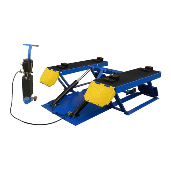
PRODUCT FEATURES AND SPECIFICATIONS LR10 Portable Low-rise Lift Features Automatic safety lock :3 position safety lock . Automatic safety lock release. Portable unit is easy to move with the power unit stand . High speed: From 0-600 mm (23-5/8 ) in just 33 seconds. -
Page 3: Installation Requirement
. INSTALLATION REQUIREMENT 1 Tools Requirement 3 Grease gun 3 Screw Set 3 Socket Head Wrench Pliers 3 Wrench sets Fig.2... - Page 4 2 Power Requirement Power source must be over 2.2kw,source cable size must be over 2.5mm² and in good condition of contacting with floor. III. STEPS OF INSTALLATION A. Check the Parts Before Assembly & make sure all the parts are completed. Packaged lift, Parts box, Power Unit and Power Unit Stand.
- Page 5 Check the parts of the parts bag according to the parts bag list (See Fig. 5) Fig. 5 Install Hydraulic Power Unit ( See Fig. 6) Fig.6...
- Page 6 C. Install Connecting , Needle Valve, and Oil Hose.(See Fig.7) Pay attention to the mounting of winding PTFE thread seal tape and direction of needle valve Fig.7...
- Page 7 D. Install Electric System Refer to electric schenatic diagram, connect the power supply according to the requirement of motor nameplate. Note: The lift must be good grounding and pay attention to the direction of motor rotation when using 380V motor. PEAK Wire connection for single phase hydraulic power unit motor (Fig.8) 1.
- Page 8 Wire connection for three phase hydraulic power unit motor 1. Electric schematic diagram (See Fig.10) Push button Fig.10 Steps for connection (See Fig.11) Three Power supply wires marked (L1 L2 L3) connected with A.C.contactor terminal marked L1 L2 L3 respectively. A.C.
-
Page 9: Exploded View
IV. EXPLODED VIEW Model LR10 Fig.12 CYLINDER Fig.13... - Page 10 Roller Assy. Fig.14 Single Phase Power Unit PEAK Single Phase Single Phase Power Unit Power Unit Fig.15...
- Page 11 SPX&PEAK Hydraulic power unit valve SPX Single Phase Power Unit (Fig.16) Capacitor Relif Valve retaining wire sets Return port Technology check valve Hole Technology Hole Release Valve Release Valve Oil outlet handle Fig.16 PEAK Single Phase Power Unit (Fig.17) Running Capacitor retaining wire sets Start Capacitor...
- Page 12 . OPERATION INSTRUCTIONS 1. Install the oil hose between oil cylinder and power unit, connect with the power supply wire well. The machine can be ready to use. 2. The roller assy must be disengage when lifting vehicle (See Fig.20). 3.
- Page 13 6. There are four fixed holes in the machine, can fix the machine on ground by anchor bolts. See Fig.23 Fig.23 . MAINTENANCE SCHEDULE Monthly: Fig.24 Maintance all the running friction parts with grease Check all the joint,bolt or pin to make sure good connection. Visual check if all the hydraulic holes are weared and leaking.
- Page 14 VII. TROUBLE SHOOTING Trouble CAUSE REMEDY Button does not work Replace button Wiring connections are not in good condition or Repair all wiring connection disconnection Motor does not run Motor burned out Repair or replace motor AC Contactor in damage Replace AC contactor Motor runs in reverse rotation Reverse two power wire...
-
Page 15: Parts List
VIII. PARTS LIST Item Part No. Description QTY. Note 630001A Platform 206019 Snap ring 19 630003 Pin for Drive-thru Ramp 19*452 630106 Bracket Pin 19*410 Bracket 630107 630108 Ramp 630109 Connecting pin for cylinder 25*92 Cylinder 630006 630007 Cylinder cover connecting pin 25*132 206032 Snap ring 25 630008... - Page 16 LR10 Hydraulic Cylinder Item Part No. Description QTY. Note Cylinder tube Piston Rod Silencer Head cap Dust ring O - Ring O - Ring Piston O-Ring O-Ring Y-Ring OSI wear ring Zerk Roller Assy. Item Part No. Description QTY. Note...
- Page 17 Item Part No. Description QTY. Note Cover of Capacitor Hex Bolt Cover of Motor Terminal Box Oil Outlet Release Valve Release Valve Handle Hex Nut Check Valve Gear Pump Oil Return Pipe Filler Cap PEAK Single Phase Hydraulic Power Unit Item Part No.
- Page 18 Item Part No. Description QTY. Note 28A-23 209100A Oil Outlet 28A-24 209105A Check Valve Release Valve 28A-25 209101A Release Valve Handle 28A-26 209102A 28A-27 209103A Washer 28A-28 209104A Hex Nut 28A-29 209106A Gear Pump 28A-30 209107A Oil Return Pipe 28A-31 209108A Filler Cap...
Need help?
Do you have a question about the LR10 and is the answer not in the manual?
Questions and answers