Table of Contents
Advertisement
Advertisement
Table of Contents
Troubleshooting

Related Manuals for Mitsubishi Electric QS001CPU


Summary of Contents for Mitsubishi Electric QS001CPU
- Page 1 QSCPU User's Manual (Hardware Design, Maintenance and Inspection) -QS001CPU...
-
Page 3: Safety Precautions
SAFETY PRECAUTIONS (Read these precautions before using this product.) Before using this product, please read this manual and the relevant manuals carefully and pay full attention to safety to handle the product correctly. In this manual, the safety precautions are classified into two levels: " WARNING"... - Page 4 [Design Precautions] WARNING All output signals from a safety CPU module to the CC-Link Safety system master module are prohibited to use. These signals can be found in the CC-Link Safety System Master Module User's Manual. Do not turn ON or OFF these signals by sequence program, since turning ON/OFF these output signals of the programmable controller system may cause malfunctions and safety operation cannot be guaranteed.
- Page 5 [Installation Precautions] CAUTION Use the safety programmable controller in an environment that meets the general specifications in this manual. Failure to do so may result in electric shock, fire, malfunction, or damage to or deterioration of the product. To mount the module, while pressing the module mounting lever located in the lower part of the module, fully insert the module fixing projection(s) into the hole(s) in the base unit and press the module until it snaps into place.
- Page 6 [Wiring Precautions] CAUTION Individually ground the FG and LG terminals of the programmable controller with a ground resistance of 100 or less. Failure to do so may result in electric shock or malfunction. Use a solderless terminal with insulation sleeve for wiring of a terminal block. Use up to two solderless terminals for a single terminal.
- Page 7 [Wiring Precautions] CAUTION Mitsubishi programmable controllers must be installed in control panels. Connect the main power supply to the power supply module in the control panel through a relay terminal block. Wiring and replacement of a power supply module must be performed by qualified maintenance personnel with knowledge of protection against electric shock.
- Page 8 [Startup and Maintenance Precautions] CAUTION The online operations performed from a personal computer to a running safety programmable controller (Program change when a safety CPU module is RUN, device test, and operating status change such as RUN-STOP switching) have to be executed after the manual has been carefully read and the safety has been ensured.
- Page 9 [Disposal Precautions] CAUTION When disposing of this product, treat it as industrial waste. When disposing of batteries, separate them from other wastes according to the local regulations. (For details of battery regulations in EU member states, refer to Appendix 4.) [Transportation Precautions] CAUTION When transporting lithium batteries, follow the transportation regulations.
-
Page 10: Conditions Of Use For The Product
CONDITIONS OF USE FOR THE PRODUCT (1) Although MELCO has obtained the certification for Product's compliance to the international safety standards IEC61508, ISO13849-1 from TUV Rheinland, this fact does not guarantee that Product will be free from any malfunction or failure. The user of this Product shall comply with any and all applicable safety standard, regulation or law and take appropriate safety measures for the system in which the Product is installed or used and shall take the second or third safety measures other than the Product. -
Page 11: Revisions
REVISIONS The manual number is given on the bottom left of the back cover. Print Date Manual Number Revision Sep., 2006 SH(NA)-080626ENG-A First edition May, 2007 SH(NA)-080626ENG-B Correction Section 2.2, 4.1, 5.1, 6.1, 9.1.1, 9.1.3, 10.1, 10.3.1, 10.3.2, 12.2.1, 12.2.10 Addition Section 12.2.12 Apr., 2008... - Page 12 This manual confers no industrial property rights or any rights of any other kind, nor does it confer any patent licenses. Mitsubishi Electric Corporation cannot be held responsible for any problems involving industrial property rights which may occur as a result of using the contents noted in this manual.
-
Page 13: Table Of Contents
INTRODUCTION Thank you for choosing the Mitsubishi Electric MELSEC-QS series of Safety Programmable Controllers. Before using the equipment, please read this manual carefully to develop full familiarity with the functions and performance of the QS series programmable controller you have purchased, so as to ensure correct use. - Page 14 CHAPTER6 BASE UNIT 6 - 1 to 6 - 2 Specification ............................ 6 - 1 Part Names ............................6 - 2 CHAPTER7 BATTERY 7 - 1 to 7 - 2 Battery (Q6BAT) ..........................7 - 1 7.1.1 Battery Specifications ....................... 7 - 1 7.1.2 Installation of Battery ........................
- Page 15 11.4 When programmable controller Has been Stored without a Battery..........11 - 10 11.5 When Battery Has Gone Flat during Storage of a programmable controller ....... 11 - 11 CHAPTER12 TROUBLESHOOTING 12 - 1 to 12 - 101 12.1 Troubleshooting Basics ......................... 12 - 1 12.2 Troubleshooting Flowchart ......................
-
Page 16: Contents
(Related manual)....QSCPU User's Manual (Function Explanation, Program Fundamentals) CONTENTS CHAPTER1 OVERVIEW Features Program Storage and Operation Devices and Instructions Convenient for Programming How to Check the Serial No. and Function Version CHAPTER2 PERFORMANCE SPECIFICATION CHAPTER3 SEQUENCE PROGRAM EXECUTION Sequence Program 3.1.1 Sequence program description method 3.1.2... - Page 17 5.1.1 Memory configuration and storable data 5.1.2 Program memory 5.1.3 Standard ROM 5.1.4 Standard ROM program execution (boot run) and writing Program File Structure File Operation by GX Developer and Handling Precautions 5.3.1 File operation 5.3.2 Precautions for handling files 5.3.3 Memory capacities of files 5.3.4...
- Page 18 CHAPTER7 COMMUNICATION WITH INTELLIGENT FUNCTION MODULE Communication with CC-Link Safety Master Module Communication with CC-Link IE Field Network Master/Local Module (With Safety Functions) Communication with CC-Link IE Controller Network Module or MELSECNET/H Module Communication with Ethernet Module Communication using intelligent function module dedicated instructions CHAPTER8 PARAMETERS PLC Parameters Network Parameters...
- Page 19 11.1 Items to be examined for program creation 11.2 Procedure for writing program 11.3 Boot run procedure APPENDICES Appendix 1 Special Relay List Appendix 2 Special Register List Appendix 3 Parameter Number List Appendix 4 Restrictions on Using CC-Link IE Controller Network Module with Safety CPU Module Appendix 5 Restrictions on Using MELSECNET/H Module with Safety CPU Module Appendix 6 Restrictions on Using Ethernet Module with Safety CPU Module Appendix 7 Dedicated Instructions which can be used in Safety CPU Module...
-
Page 20: About Manuals
ABOUT MANUALS Introduction Manual Read the following manual before designing and constructing a safety system. Manual No. Manual Name (Model Code) Safety Application Guide SH-080613ENG Explains the overview, construction method, laying and wiring examples, and application programs of the (13JR90) safety-related system. - Page 21 Manual No. Manual Name (Model Code) MELSEC-Q/L Ethernet Interface Module User's Manual (Application) Explains the e-mail function, programmable controller CPU status monitoring function, communication function via SH-080010 CC-Link IE Controller Network, MELSECNET/H or MELSECNET/10, communication function using the data link (13JL89) instructions, file transfer function (FTP server) of the Ethernet module.
-
Page 22: How This Manual Is Organized
HOW THIS MANUAL IS ORGANIZED Reference destination Chapter heading A reference destination or The index on the right side of the page reference manual is marked shows the chapter of the open page at a glance. Section title The section of the open page is shown at a glance. -
Page 23: How To Use This Manual
HOW TO USE THIS MANUAL This manual is prepared for users to understand the hardware specifications of those modules such as the CPU modules, power supply modules, and base units, maintenance and inspections of the system, and troubleshooting required when you use QS series programmable controllers. -
Page 24: Generic Terms And Abbreviations
CC-Link IE Controller Network module, MELSECNET/H module, and Ethernet module Battery Abbreviation for the Q6BAT type battery Blank cover Abbreviation for the QG60 type blank cover Generic term for the Mitsubishi Electric Graphic Operation Terminal GOT-A*** series, GOT-F*** series and GOT1000 series - 22... -
Page 25: Precautions For Use
PRECAUTIONS FOR USE Precautions for the first use of the QS series CPU module When using a CPU module for the first time, the PLC memory needs to be initialized using GX Developer. For details of PLC memory initialization, refer to the following manual. GX Developer Operating Manual (Safety Programmable Controller) Precautions on battery (1) When running the CPU module that has been stored without battery... -
Page 26: Chapter1 Overview
CHAPTER1 OVERVIEW This manual describes the hardware specifications and handling methods of the QS series CPU module, QS001CPU. The manual also describes the specifications of the power supply module, base, unit, and battery. For the functions, programs, and devices of the QS series CPU module, refer to the following. - Page 27 OVERVIEW (1) List of QS Series CPU Module manuals The QS series CPU module manuals are as shown below. For details such as manual numbers, refer to "About Manuals" in this manual. Table1.1 List of manuals of QS Series CPU module Program Maintenance Common...
-
Page 28: Features
OVERVIEW 1.1 Features The QS series CPU module has the following new features: (1) Safety programmable controller system can be constructed The QS series CPU module has acquired certification of the highest safety level (SIL3 of IEC 61508, Category 4 of EN 654-1, and Category 4 performance level "e" of EN ISO 13849-1) applicable to programmable controllers. - Page 29 OVERVIEW (2) The safety CPU operation mode is equipped for safe system operation The CPU module is equipped with two safety CPU operation modes. "SAFETY MODE" for safe system operation and "TEST MODE" for system construction and maintenance. These two modes prevent the user's erroneous operations for safe system operation. (a) SAFETY MODE SAFETY MODE is a mode for safe system operation.
- Page 30 OVERVIEW (4) Enhanced RAS (a) Enhanced memory diagnostics The memory diagnostics equipped with the CPU module are enhanced. (b) Redundant CPU The CPU module has two CPUs (CPU A and CPU B). The operation results of CPU A/CPU B are compared, and output only when the results are matched so that incorrect outputs can be prevented.
- Page 31 OVERVIEW (5) USB interface is equipped The CPU module is equipped with the USB interface to communicate with a programming tool. Personal computer Figure 1.3 Connection to a personal computer using USB (6) Connectable with personal computers and standard programmable controllers The CPU module can read data from the MELSOFT products installed in the personal computer and also can communicate data between safety programmable controller...
- Page 32 OVERVIEW (7) Safety communication in the CC-Link IE Field Network A CC-Link IE Field Network master/local module (with safety functions) enables safety communication between safety CPU modules. In addition, safety and standard communications can be used on the same network. These factors allow a safety programmable controller to be simply added to the existing CC-Link IE Field Network.
-
Page 33: Chapter2 System Configuration
2.1 System Configuration The following figure shows the system configuration of the safety programmable controller system when the QS series CPU module is used. (1) System configuration when the CPU(QS001CPU) is used Battery for a CPU (Q6BAT) QS001CPU CPU module... - Page 34 SYSTEM CONFIGURATION (2) System configuration overview Base unit (QS034B) Slot number I/O number Power supply module CPU module Figure 2.2 System configuration Table2.1 Base unit and power supply module applicable to system configuration Base unit model name QS034B Maximum number of 4 modules mountable modules Power supply module model...
- Page 35 (100VAC) QS061P-A2-K An S-mark certified safety power supply module (200VAC) A module which is mounted on a safety main base unit and QS001CPU performs logic operations for safety control Safety CPU module QS001CPU-K An S-mark...
-
Page 36: Precautions For System Configuration
Table2.3 Modules mountable on the main base unit Number of modules Module Model Remarks mounted in one system CPU module • QS001CPU Only one • QS061P-A1 Only one (only one of the module Power supply module • QS061P-A2 models) CC-Link Safety master •... -
Page 37: Configuration Of Peripheral Devices
SYSTEM CONFIGURATION 2.2 Configuration of Peripheral Devices This section describes the configuration of the peripheral devices usable in the safety programmable controller system. QS001CPU Personal computer (GX Developer Version 8.40S or later) USB cable*1 * 1: For details of the USB cable, refer to "About the USB cable (QCPU (Q mode) compatible)" of the following manual. -
Page 38: Checking Serial Number And Function Version
SYSTEM CONFIGURATION 2.3 Checking Serial Number and Function Version The serial number and function version of the CPU module can be checked on the rating plate or the System monitor window in GX Developer. (1) Checking on the rating plate The rating plate is located on the side of the CPU module. - Page 39 SYSTEM CONFIGURATION (3) Checking on the System monitor window (Product Information List window) To display the window for checking the serial number and function version, select [Diagnostics] [System monitor] and click the Product Information List button in GX Developer. On the window, the serial number and function version of intelligent function modules can also be checked.
-
Page 40: Chapter3 General Specifications
: Do not use or store the programmable controller under pressure higher than the atmospheric pressure of altitude 0m. Doing so may cause malfunction. When using the programmable controller under pressure, please consult your local Mitsubishi Electric representative. - Page 41 GENERAL SPECIFICATIONS Memo...
-
Page 42: Chapter4 Cpu Module
CPU MODULE CHAPTER4 CPU MODULE 4.1 Performance Specifications Table4.1 shows the performance specifications of the CPU module. Table4.1 Performance Specifications Item QS001CPU Remarks Control method Repetitive operation of stored program ---- I/O control mode Refresh mode ---- Program Sequence control Relay symbol language, function block. - Page 43 CPU MODULE Table4.1 Performance Specifications (Continue) Item QS001CPU Remarks Internal relay [M] 6144 points by default (M0-6143) (changeable) Link relay [B] 2048 points by default (B0 to 7FF) (changeable) 512 points by default (T0 to 511) (changeable) (Sharing of low- and high-speed timers) The low- and high-speed timers are specified by the instructions.
-
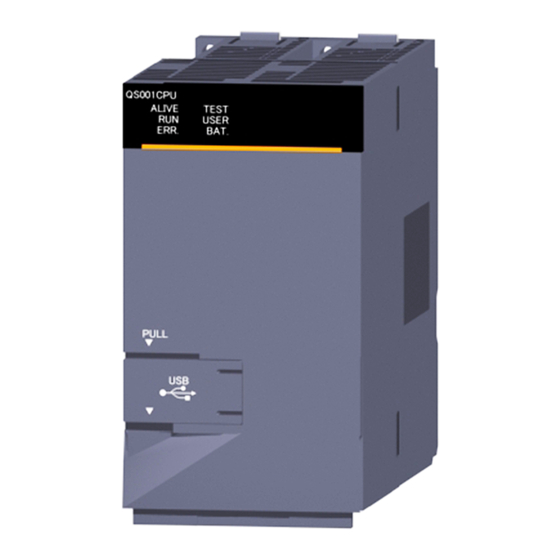
Page 44: Part Names
CPU MODULE 4.2 Part Names QS001CPU ALIVE TEST ALIVE TEST USER USER ERR. BAT. ERR. BAT. BAT. PULL STOP PULL RESET RUN When opening the cover, put your finger here. Figure 4.1 Front face Figure 4.2 With front cover open Figure 4.3 Side Face... -
Page 45: Sequence Program Operation
CPU MODULE Table4.2 Part Names Name Application Module fixing hook Hook used to fix the module to the base unit. : Normal "ALIVE" LED : When the hardware watchdog timer error is detected (Green) ("ERR." LED is On.) Indicates the operating mode of the CPU module. : TEST MODE Flash : When TEST MODE is switched to SAFETY MODE "TEST"... -
Page 46: Switch Operation After Writing A Program
CPU MODULE 4.3 Switch Operation after Writing a Program Programs can be written to the CPU module in either the STOP or RUN status. (1) When writing a program with the CPU module set to "STOP" (a) Set the RUN/STOP/RESET switch to STOP. The "RUN"... -
Page 47: Reset Operation
CPU MODULE 4.4 Reset Operation For the CPU module, the RUN/STOP/RESET switch of the CPU module is used to switch between the "RUN status" and "STOP status" and to perform "RESET operation". When using the RUN/STOP/RESET switch to reset the CPU module, moving the RUN/ STOP/RESET switch to the reset position will not reset it immediately. - Page 48 CPU MODULE POINT Operate the RUN/STOP/RESET switch with your fingertips. Do not use any tool such as a screwdriver because the switch part might be damaged. 4.4 Reset Operation...
-
Page 49: Chapter5 Power Supply Module
POWER SUPPLY MODULE CHAPTER5 POWER SUPPLY MODULE This section describes the specifications of the power supply modules applicable for the programmable controller system and how to select the most suitable module. 5.1 Specifications Table5.1 shows the specifications of the power supply modules. Table5.1 Power supply module specifications Performance Specifications Item... - Page 50 POWER SUPPLY MODULE Table5.1 Power supply module specifications (Continue) Performance Specifications Item QS061P-A1 QS061P-A2 Application Section 5.3) ERR. contact Rated switching 24VDC, 0.5A voltage/current Min. switching load 5VDC, 1mA Response time ON: 10ms or less, ON OFF: 12ms or less Mechanical : 20 million times or more Life Electrical : Rated switching voltage/current load: 100 thousand times or more...
-
Page 51: Precaution When Connecting The Uninterruptible Power Supply
POWER SUPPLY MODULE 5.2 Precaution when connecting the uninterruptible power supply Be sure of the following terms when connecting the QS Series CPU Module system to the uninterruptible power supply (abbreviated as UPS hereafter): Use an online UPS (uninterruptible power supply) with power distortion factor of 5% or less or line-interactive UPS. -
Page 52: Names Of Parts And Settings
POWER SUPPLY MODULE 5.3 Names of Parts and Settings The names of the parts of each power supply module are described below. QS061P-A1 (100 to 120VAC input, 5VDC 6A output) QS061P-A2 (200 to 240VAC input, 5VDC 6A output) <QS061P-A1> 9),10) Figure 5.1 Power supply module 5.3 Names of Parts and Settings... - Page 53 POWER SUPPLY MODULE Table5.2 Part names Name Application On (green) : Normal (5VDC output, instantaneous power failure within 20ms) : • AC power supply is ON, however, the power supply module is out of order. "POWER" LED (5VDC error, overload, internal circuit failure, fuse blown) •...
-
Page 54: Chapter6 Base Unit
BASE UNIT CHAPTER6 BASE UNIT This section describes the specifications of the base units used in the programmable controller system. 6.1 Specification The base unit is a unit to which the CPU module, power supply module and/or intelligent function module are installed. Table6.1 Base unit specifications Type Item... -
Page 55: Part Names
BASE UNIT 6.2 Part Names The names of the parts of the base unit are described below. I/O0 I/O1 I/O2 I/O3 POWER Figure 6.1 Base unit (QS034B) Table6.2 Part Names Name Application Base cover Cover for protecting the printed-circuit board of the base unit Connector for installing the QS series power supply module, CPU module and intelligent function module. -
Page 56: Chapter7 Battery
BATTERY CHAPTER7 BATTERY This section describes the specifications of the batteries available for the QS series CPU module and how to handle them. 7.1 Battery (Q6BAT) Batteries (Q6BAT) are installed in the CPU module to retain data of the program memory and operation/error history in case of power failure. -
Page 57: Installation Of Battery
BATTERY 7.1.2 Installation of Battery The battery for the CPU module is shipped with its connector disconnected. Connect the connector as follows. Refer to Section 11.3 for the service life of the battery and how to replace the battery. CPU module Open the CPU module front cover. -
Page 58: Chapter8 Cpu Module Start-Up Procedures
CPU MODULE START-UP PROCEDURES CHAPTER8 CPU MODULE START-UP PROCEDURES This chapter describes the procedure for starting up the CPU module. It is assumed that programs and parameters have been created separately. 8.1 Procedure before Operating in SAFETY MODE This section describes the procedure before operating the CPU module in SAFETY MODE. - Page 59 CPU MODULE START-UP PROCEDURES (Continued from the previous page) Installing a battery CHAPTER 7 Install a battery to the CPU module. Powering ON the power supply module CHAPTER 4, CHAPTER 5, Confirm the following items of the safety programmable controller system, and then turn on CHAPTER 10 the power supply.
- Page 60 CPU MODULE START-UP PROCEDURES (Continued from the previous page) CHAPTER 4 Stopping the CPU module Set the RUN/STOP/RESET switch of the CPU module to the STOP position. GX Developer Version 8 Switching to SAFETY MODE Operating Manual (Safety Switch the mode from TEST MODE to SAFETY MODE by selecting the menu option, Programmable Controller) "Switch safety CPU operation mode", in GX Developer.
- Page 61 CPU MODULE START-UP PROCEDURES Memo 8.1 Procedure before Operating in SAFETY MODE...
-
Page 62: Chapter9 Emc, Low Voltage, And Machinery Directives
TUV Rheinland (1) Authorized representative in Europe Authorized representative in Europe is shown below. Name : MITSUBISHI ELECTRIC EUROPE B.V. Address: Mitsubishi-Electric-Platz 1, 40882 Ratingen, Germany 9.1 Requirements for Conformance to EMC Directive The EMC Directive specifies that products placed on the market must "be so constructed that they do not cause excessive electromagnetic interference (emissions) and are not unduly affected by electromagnetic interference (immunity)". -
Page 63: Standards Relevant To The Emc Directive
EMC, LOW VOLTAGE, AND MACHINERY DIRECTIVES 9.1.1 Standards relevant to the EMC Directive (1) Emission related standards Table9.1 Emission related standards Standard Test item Test description Value specified in standard • 30 to 230MHz, QP: 40dBµV/m (measured at 10m The electromagnetic wave which CISPR16-2-3 distance) the product emits to the external... -
Page 64: Installation In A Control Panel
EMC, LOW VOLTAGE, AND MACHINERY DIRECTIVES 9.1.2 Installation in a control panel The programmable controller is open equipment and must be installed within a control panel for use.* This not only ensures safety but also ensures effective shielding of programmable controller-generated electromagnetic noise. -
Page 65: Cables
EMC, LOW VOLTAGE, AND MACHINERY DIRECTIVES 9.1.3 Cables The cables pulled out from the control panel contain a high frequency noise component. On the outside of the control panel, therefore, they serve as antennas to emit noise. To prevent noise emission, use shielded cables when pulling out the cables which are connected to intelligent function module and CC-Link Safety remote I/O module and using them outside of the control panel. - Page 66 EMC, LOW VOLTAGE, AND MACHINERY DIRECTIVES (2) MELSECNET/H module Be sure to use double-shielded coaxial cables (MITSUBISHI CABLE INDUSTRIES, LTD.: 5C-2V-CCY) for the coaxial cables of MELSECNET/H module. Radiated noise in the range of 30HMz or higher can be suppressed by using double-shielded coaxial cables.
- Page 67 EMC, LOW VOLTAGE, AND MACHINERY DIRECTIVES • Be sure to use double-shielded coaxial cables for the coaxial cables*2 connected to the 10BASE2 connectors. Ground the double-shielded coaxial cable by connecting its outer shield to the ground Shield Ground here Figure 9.7 Double-shielded coaxial cable grounding Refer to (1) for the shield grounding processing.
-
Page 68: Power Supply Module
EMC, LOW VOLTAGE, AND MACHINERY DIRECTIVES 9.1.4 Power Supply Module Always ground the LG and FG terminals after short-circuiting them. 9.1.5 Others (1) Ferrite core A ferrite core has the effect of reducing conduction noise in around 10MHz band and radiated noise in the 30MHz to 100MHz band. - Page 69 EMC, LOW VOLTAGE, AND MACHINERY DIRECTIVES (2) Noise filter (power supply line filter) A noise filter is a component which has an effect on conducted noise. It is not required to fit the noise filter to the power supply line, but fitting it can further suppress noise.
-
Page 70: Requirement To Conform To The Low Voltage Directive
EMC, LOW VOLTAGE, AND MACHINERY DIRECTIVES 9.2 Requirement to Conform to the Low Voltage Directive The Low Voltage Directive requires each device that operates with the power supply ranging from 50 to 1000VAC and 75 to 1500VDC to satisfy the safety requirements. In Section 9.2.1 to Section 9.2.5, cautions on installation and wiring of the MELSEC-QS series programmable controller to conform to the Low Voltage Directive are described. -
Page 71: Power Supply
EMC, LOW VOLTAGE, AND MACHINERY DIRECTIVES 9.2.3 Power supply The insulation specification of the power supply module was designed assuming installation category II. Be sure to use the installation category II power supply to the programmable controller. The installation category indicates the durability level against surge voltage generated by a thunderbolt. - Page 72 EMC, LOW VOLTAGE, AND MACHINERY DIRECTIVES (2) Dustproof and waterproof features The control panel also has the dustproof and waterproof functions. Insufficient dustproof and waterproof features lower the insulation withstand voltage, resulting in insulation destruction. The insulation in our programmable controller is designed to cope with the pollution level 2, so use in an environment with pollution level 2 or below.
-
Page 73: External Wiring
EMC, LOW VOLTAGE, AND MACHINERY DIRECTIVES 9.2.5 External wiring (1) 24VDC external power supply To connect to the CC-Link Safety remote I/O module, use the power supply that meets the following conditions: • SELV (Safety Extra Low Voltage): Product with reinforced insulation from the hazardous potential part (48V or more) •... -
Page 74: Requirements For Compliance With The Machinery Directive
EMC, LOW VOLTAGE, AND MACHINERY DIRECTIVES 9.3 Requirements for compliance with the Machinery Directive The Machinery Directive requires that machinery satisfy the three pillars of safety: mechanical safety, electrical safety, and worker safety. This product complies with the Machinery Directive (2006/42/EC). Before using this product, please read this manual, the relevant manuals, the manuals for standard programmable controller, and the safety standards carefully and pay full attention to safety to handle the product correctly. -
Page 75: Chapter10 Loading And Installation
LOADING AND INSTALLATION CHAPTER10 LOADING AND INSTALLATION In order to increase the reliability of the system and exploit the maximum performance of its functions, this section describes the methods and precautions for the mounting and installation of the system. When a safety programmable controller detects an error in an external power supply or a failure in programmable controller, it turns off all the WARNING outputs. - Page 76 LOADING AND INSTALLATION When a safety remote I/O module has detected a CC-Link Safety error, it turns off all the outputs. WARNING Note that the outputs in a sequence program are not automatically turned off. If a CC-Link Safety or CC-Link IE Field Network error has been detected, create a sequence program that turns off the outputs in the program.
-
Page 77: Calculating Heat Generation Of Programmable Controller
LOADING AND INSTALLATION 10.1 Calculating Heat Generation of programmable controller The ambient temperature inside the panel storing the programmable controller must be suppressed to an ambient temperature of 55 or less, which is specified for the programmable controller. For the design of a heat releasing panel, it is necessary to know the average power consumption (heating value) of the devices and instruments stored inside. - Page 78 (3) Example of calculation of average power consumption (a) System configuration QS061P-A1 QS001CPU QS034 QS0J61BT12 Figure 10.1 System configuration (b) 5 VDC current consumption of each module QS001CPU : 0.43(A)
-
Page 79: Module Installation
LOADING AND INSTALLATION 10.2 Module Installation 10.2.1 Installation precautions Use the safety programmable controller in an environment that meets the general specifications in this manual. CAUTION Failure to do so may result in electric shock, fire, malfunction, or damage to or deterioration of the product. To mount the module, while pressing the module mounting lever located in the lower part of the module, fully insert the module fixing projection(s) into the hole(s) in the base unit and press the module until it snaps into... - Page 80 LOADING AND INSTALLATION This section gives instructions for handling the CPU, and power supply modules, base unit and so on. • Do not drop the module case and main module or subject them to strong impact. • Do not remove modules' printed circuit boards from the enclosure in order to avoid failures in operation.
- Page 81 LOADING AND INSTALLATION 4) Fit the mounting screws into the holes at the bottom of the base unit, and then retighten the 4 mounting screws. Note1 : Install the base unit to a panel, with no module loaded in the right-end slot.
- Page 82 LOADING AND INSTALLATION (c) Applicable DIN rail types (IEC 60715) TH35-7.5Fe TH35-7.5AI TH35-15Fe (d) DIN rail mounting screw intervals When using either the TH35-7.5Fe or TH35-7.5Al DIN rail, tighten rail mounting screws with an interval of 200mm or less to ensure that the rail has sufficient strength.
- Page 83 LOADING AND INSTALLATION POINT (1) Use only one washer for each mounting screw. Use only the square washers supplied with the adapters. If two or more washers are used together for one mounting screw, the screw may interfere with the base unit. (2) Make sure to align the square washer sides with the DIN rail.
- Page 84 LOADING AND INSTALLATION (e) Stopper mounting When using the DIN rail in a large vibration and/or shock prone environment, install the base unit using the stoppers supplied with the DIN rail adapters indicated in (a). Hook Stopper Loosen the screw at the top of the stopper.
- Page 85 LOADING AND INSTALLATION POINT When stoppers are used, the dimension of stoppers need to be considered in the unit installation dimensions. Refer to Section 6.1 for the base unit dimensions (W). Base unit Stopper Stopper DIN rail Base unit width: W DIN rail center W+18 Unit: mm...
-
Page 86: Instructions For Mounting The Base Unit
LOADING AND INSTALLATION 10.2.2 Instructions for mounting the base unit When mounting the programmable controller to an enclosure or similar, fully consider its operability, maintainability and environmental resistance. (1) Module mounting position Keep the clearances shown in Figure 10.13 between the top/bottom faces of the module and other structures or parts to ensure good ventilation and facilitate module replacement. - Page 87 LOADING AND INSTALLATION (2) Module mounting orientation • Install the programmable controller in the orientation in Figure 10.14 to ensure good ventilation for heat release. Figure 10.14 Orientation in which modules can be mounted • Do not mount it in either of the orientations shown in Figure 10.15. Vertical mounting Horizontal installation Horizontal mounting...
- Page 88 LOADING AND INSTALLATION (3) Installation surface Mount the base unit on a flat surface. If the mounting surface is not even, this may strain the printed circuit boards and cause malfunctions. (4) Installation of unit in an area where the other devices are installed Avoid mounting base unit in proximity to vibration sources such as large magnetic contractors and no-fuse circuit breakers;...
-
Page 89: Installation And Removal Of Module
LOADING AND INSTALLATION 10.2.3 Installation and removal of module This section explains how to install and remove a power supply, CPU, intelligent function or another module to and from the base unit. (1) Installation and removal of the module from the QS034B the QS034B (a) Installation of module on Base unit... - Page 90 LOADING AND INSTALLATION POINT 1. When mounting the module, always insert the module fixing latch into the module fixing hole of the base unit. At that time, securely insert the module fixing latch so that it does not come off from the module fixing hole.
- Page 91 LOADING AND INSTALLATION (b) Removal from the QS034B Remove the module fixing screw. Then support the module with both hands and securely press the module fixing hook*1 with your finger. Push Lifting Pull the module based on the supporting point of module bottom Module fixing while pressing the module fixing hook *1...
-
Page 92: Wiring
LOADING AND INSTALLATION 10.3 Wiring 10.3.1 Wiring precautions Shut off the external power supply (all phases) used in the system before wiring. WARNING Failure to do so may result in electric shock or damage to the product. After wiring, attach the included terminal cover to the module before turn- ing it on for operation. - Page 93 LOADING AND INSTALLATION Individually ground the FG and LG terminals of the programmable con- troller with a ground resistance of 100 or less. Failure to do so may CAUTION result in electric shock or malfunction. Use a solderless terminal with insulation sleeve for wiring of a terminal block.
- Page 94 LOADING AND INSTALLATION (1) Power supply wiring • Separate the programmable controller power supply line from the lines for I/O devices and power devices as shown below. When there is much noise, connect an insulation transformer. • Taking rated current or inrush current into consideration when wiring the power supply, be sure to connect a breaker or an external fuse that have proper blown and detection.
- Page 95 LOADING AND INSTALLATION POINT 1. Separate the ground of the surge absorber for lightning (E1) from that of the programmable controller (E2). 2. Select a surge absorber for lightning whose power supply voltage does no exceed the maximum allowable circuit voltage even at the time of maximum power supply voltage elevation.
-
Page 96: Connecting To The Power Supply Module
LOADING AND INSTALLATION 10.3.2 Connecting to the power supply module The following figure shows the wiring example of power lines, grounding lines, etc. to the unit. Main base unit 100/110VAC (QS034B) CPU module QS061P-A1 Fuse ERR 1 24VDC INPUT 100-120VAC Connect to 24VDC terminals of module that requires 24VDC... -
Page 97: Chapter11 Maintenance And Inspection
MAINTENANCE AND INSPECTION CHAPTER11 MAINTENANCE AND INSPECTION Do not touch the terminals while power is on. Doing so could cause shock or erroneous operation. WARNING Correctly connect the battery. Also, do not charge, disassemble, heat, place in fire, short circuit, or solder the battery. - Page 98 MAINTENANCE AND INSPECTION The online operations performed from a personal computer to a running safety programmable controller (Program change when a CAUTION safety CPU is RUN, device test, and operating status change such as RUN-STOP switching) have to be executed after the manual has been carefully read and the safety has been ensured.
-
Page 99: Daily Inspection
MAINTENANCE AND INSPECTION 11.1 Daily Inspection The items that must be inspected daily are listed in Table11.1. Table11.1 Daily inspection Item Inspection Item Inspection Judgment Criteria Remedy Check that fixing screws are The screws and cover must Installation of base unit not loose and the cover is Retighten the screws. -
Page 100: Periodic Inspection
MAINTENANCE AND INSPECTION 11.2 Periodic Inspection The items that must be inspected one or two times every 6 months to 1 year are listed below. When the equipment is moved or modified, or layout of the wiring is changed, also perform this inspection. -
Page 101: Battery Life And Replacement Procedure
MAINTENANCE AND INSPECTION 11.3 Battery Life and Replacement Procedure The battery installed in the safety CPU module is used for data retention of the program memory and operation/error history during the power failure. Special relays SM51 and SM52 turn on due to the decrease of battery voltage. Even if the special relays turn on, the program and operation/error data are not erased immediately. -
Page 102: Battery Lives Of Cpu Modules
43,800hr 710hr 2.96 years 5.00 years 30 days 37,142hr 43,800hr 710hr 4.23 years 5.00 years 30 days 43,800hr 43,800hr 710hr QS001CPU 5.00 years 5.00 years 30 days 43,800hr 43,800hr 710hr 5.00 years 5.00 years 30 days 43,800hr 43,800hr 710hr 100% 5.00 years... - Page 103 MAINTENANCE AND INSPECTION POINT 1. Use the battery within the time shown by the guaranteed value of the battery life. If the battery may be used exceeding the time shown by the guaranteed battery life value, perform the following. • Back up programs and the operation/error history in advance after SM52 turns on (within backup time after alarm).
-
Page 104: Replacement Procedure Of The Cpu Module Battery
MAINTENANCE AND INSPECTION 11.3.2 Replacement Procedure of the CPU Module Battery Replace the battery by the following procedure when the Q6BAT battery of the CPU module comes to the end of its life. The battery replacement can be performed regardless of the SAFETY MODE or TEST MODE. - Page 105 MAINTENANCE AND INSPECTION POINT After replacing a battery, write the date for next battery replacement on the sticker on the back side of the front cover. Write the proper date by checking the battery life. ( Section 11.3.1) ALIVE TEST USER ERR.
-
Page 106: When Programmable Controller Has Been Stored Without A Battery
MAINTENANCE AND INSPECTION 11.4 When programmable controller Has been Stored without a Battery When the programmable controller operation is to be resumed after being stored with the battery removed, the memories in the CPU module may be corrupted. Hence, before resuming operation, always format the memories using GX Developer. After formatting the memories, write the memory contents backed up prior to storage to each memory. -
Page 107: When Battery Has Gone Flat During Storage Of A Programmable Controller
MAINTENANCE AND INSPECTION 11.5 When Battery Has Gone Flat during Storage of a programmable controller When the programmable controller is to be used after being stored for some period of time and the battery has gone flat during storage, the memories in the CPU module may be corrupted. -
Page 108: Chapter12 Troubleshooting
TROUBLESHOOTING CHAPTER12 TROUBLESHOOTING This section describes the various types of trouble that occur when the system is operated, and causes and remedies of these troubles. 12.1 Troubleshooting Basics In order to increase the reliability of the system, not only highly reliable devices are used but also the speedy startup of the system after the occurrence of trouble becomes an important factor. -
Page 109: Troubleshooting Flowchart
TROUBLESHOOTING 12.2 Troubleshooting Flowchart The trouble investigating methods and remedies of the troubles are described below. 12.2.1 Troubleshooting category flow This section classifies the error by definition and describes them. Error-occurrence description Section 12.2.2 Flowchart for when the ERR terminal ERR terminal turned off (opened). -
Page 110: Flowchart For When The Err Terminal (Negative Logic) Is Off (Opened)
TROUBLESHOOTING 12.2.2 Flowchart for when the ERR terminal (negative logic) is off (opened) The following shows the flowchart for when the "ERR terminal" is off (opened) at power-on or during operation of the programmable controller. The ERR terminal has turned off (opened). Flashing (CPU module is in stop How is the "ERR."... - Page 111 Table12.1 Errors that can be detected by the ERR terminal of a power supply module CPU module Base unit QS001CPU AC power not input, power supply module fuse blown and CPU module stop error Main base unit (QS034B) (including reset) can be detected.
-
Page 112: Flowchart For When The "Power" Led Turns Off
TROUBLESHOOTING 12.2.3 Flowchart for when the "POWER" LED turns off The following shows the flowchart for when the "POWER" LED of the power supply module turns off at of the programmable controller power-on or during operation. The "POWER" LED has turned off. Has the "ALIVE"... - Page 113 TROUBLESHOOTING (From previous page) Check the sum of internal current consumptions of the modules that comprise the system. Does the Reexamine the system configuration total current exceed the to make the total current less than rated output current of the power the rated output current of the power supply module? supply module...
-
Page 114: When The "Alive" Led Does Not Turn On Or Turns Off
TROUBLESHOOTING 12.2.4 When the "ALIVE" LED does not turn on or turns off This section describes the troubleshooting for when the "ALIVE" LED of the CPU module does not turn on at power-ON of the programmable controller or when the "ALIVE" LED turns off during operation. - Page 115 TROUBLESHOOTING (2) When the "ALIVE" LED of the CPU module turns off during operation of the programmable controller The "ALIVE" LED of the CPU module may turn off when (a) the CPU module detects the hardware failure, or (b) the power supply module, CPU module, or intelligent function module is mounted to/removed from the base unit while the power is ON.
-
Page 116: Flowchart For When The "Run" Led Turns Off
TROUBLESHOOTING 12.2.5 Flowchart for when the "RUN" LED turns off The following shows the flowchart for when the "RUN" LED of the CPU module turns off during operation of the programmable controller. The "RUN" LED has turned off. Section 12.2.3 is the "POWER"... -
Page 117: When The "Run" Led Flashes
TROUBLESHOOTING 12.2.6 When the "RUN" LED flashes If the "RUN" LED flashes, follow the steps below. When the programs or parameters are written into the CPU module during STOP status and then the RUN/STOP/RESET switch is set from STOP to RUN, the "RUN" LED of the CPU module flashes. -
Page 118: Flowchart For When The "Err." Led Turns On Or Flashes
TROUBLESHOOTING 12.2.7 Flowchart for when the "ERR." LED turns on or flashes The following shows the flowchart for when the "ERR." LED of the CPU module turns on or flashes at of the programmable controller power-on, at operation start or during operation. The "ERR."... - Page 119 TROUBLESHOOTING (1) Flowchart for when "MODULE VERIFY ERROR" occurs The "MODULE VERIFY ERROR" has occurred. Check the slot or base unit where the error occurred with GX Developer. Has the module on the corresponding slot been Reset the CPU module. removed/mounted during operation? Has the "ERR."...
- Page 120 TROUBLESHOOTING (2) Flowchart for when "CONTROL-BUS ERROR" occurs This flowchart can be confirmed only when a specific slot/base unit can be detected by the error code. The "CONTROL-BUS ERROR" has occurred. Check the slot or base unit where the error detected by GX Developer.
-
Page 121: When The "User" Led Turns On
TROUBLESHOOTING Remark The following causes are possible when the "ERR." LED of the CPU module flashes at programmable controller power-on. Table12.2 Error messages and causes Error Message Cause Corrective Action Remove all CPU modules other The multiple CPU system is than the safety CPU module from MODULE LAYOUT configured. -
Page 122: When The "Bat." Led Turns On
TROUBLESHOOTING 12.2.9 When the "BAT." LED turns on If the "BAT." LED turns on, follow the steps described below. The "BAT." LED turns on when low battery capacity is detected in the Q6BAT installed to the CPU module. Replace the battery with a new one according to Section 11.3.2. - 15 12.2 Troubleshooting Flowchart 12.2.9 When the "BAT."... -
Page 123: Flowchart For When A Program Cannot Be Read
TROUBLESHOOTING 12.2.10 Flowchart for when a program cannot be read The following shows the flowchart for when a program cannot be read from the CPU module. A program cannot be read. Is the connection cable connected properly? Connect the connection cable properly. -
Page 124: Flowchart For When A Program Cannot Be Written
TROUBLESHOOTING 12.2.11 Flowchart for when a program cannot be written The following shows the flowchart for when programs cannot be written in the CPU module. A program cannot be written to the CPU Has the password registered? Cancel the password using GX Developer. -
Page 125: Flowchart For When The Cpu Cannot Communicate With The Gx Developer
TROUBLESHOOTING 12.2.12 Flowchart for when the CPU cannot communicate with the GX Developer The following shows the flowchart for when communication with peripheral device is disabled at connecting the CPU module with GX Developer. The CPU cannot communicate with the GX Developer. Connect the connection cable Is the connection cable properly. - Page 126 TROUBLESHOOTING (From previous page) Section 12.2.3 Flowchart for when How is the "POWER" LED the "POWER" LED turns off. of the power supply module? Is the CPU module RESET position RESET/STOP/RUN switch in Cancel the RESET. the neutral position? Other than RESET position Can the CPU communicate with the GX Developer? Replace the power supply module and...
-
Page 127: Error Code List
TROUBLESHOOTING 12.3 Error Code List If an error occurs under one of the following conditions, the QS series CPU module uses the self-diagnostic function to display error information (LED indication) and stores it in the special relay (SM) and special register (SD): •... -
Page 128: Error Codes
TROUBLESHOOTING 12.3.1 Error codes Errors are detected by the self diagnostic function of the CPU module or detected during communication with the CPU module. The relation between the error detection pattern, error detection location and error code is shown in the following table. Table12.3 The relation between the error detection pattern, error detection location and error code Error detection Error detection pattern... -
Page 129: Reading An Error Code
TROUBLESHOOTING 12.3.2 Reading an error code If an error occurs, information such as the error code and error message for troubleshooting can be read using GX Developer. To read error codes, follow the instructions described below. 1) Start GX Developer. 2) Connect the CPU module to the personal computer that started GX Developer. -
Page 130: Error Code List (1000 To 1999)
TROUBLESHOOTING 12.3.3 Error code list (1000 to 1999) The following shows the error messages from the error code 1000 to 1999, the contents and causes of the errors, and the corrective actions for the errors. Table12.4 Error code Error Common Individual LED Status Error... - Page 131 TROUBLESHOOTING Error Corresponding Code Error Contents and Cause Corrective Action (SD0) 1000 • Take noise reduction measures. Runaway or failure of the main CPU • Reset the CPU module and RUN it • Malfunctioning due to noise or other again.If the same error is displayed reason again, this suggests a CPU module 1001...
- Page 132 TROUBLESHOOTING Error Common Individual LED Status Error Diagnostic Code Information Information Operation Message ERROR Timing (SD0) (SD5 to 15) (SD16 to 26) Status 1131 1132 At power-ON/ 1133 At reset 1136 Error 1137 RAM ERROR – Flash Stop information 1141 1142 Always 1143...
- Page 133 TROUBLESHOOTING Error Corresponding Code Error Contents and Cause Corrective Action (SD0) 1131 1132 1133 1136 Hardware error of the CPU module. A fault was detected in the internal 1137 (Please consult your local Mitsubishi memory of the CPU module. representative.) 1141 1142 1143...
- Page 134 TROUBLESHOOTING Error Common Individual LED Status Error Diagnostic Code Information Information Operation Message ERROR Timing (SD0) (SD5 to 15) (SD16 to 26) Status CONTROL- At power ON/ 1411 Module No. – Flash Stop BUS ERROR At reset CONTROL- 1413 – –...
- Page 135 TROUBLESHOOTING Error Corresponding Code Error Contents and Cause Corrective Action (SD0) When performing a parameter I/O allocation the intelligent function module Reset the CPU module and RUN it could not be accessed during initial again. If the same error is displayed communications.
-
Page 136: Error Code List (2000 To 2999)
TROUBLESHOOTING 12.3.4 Error code list (2000 to 2999) The following shows the error messages from the error code 2000 to 2999, the contents and causes of the errors, and the corrective actions for the errors. Table12.5 Error code Error Common Individual LED Status Error... - Page 137 TROUBLESHOOTING Error Corresponding Code Error Contents and Cause Corrective Action (SD0) Read the common information of the error using the GX Developer, and • Intelligent function module check and/or change the module that information at power ON are corresponds to the numerical values changed.
- Page 138 TROUBLESHOOTING Error Common Individual LED Status Error Diagnostic Code Information Information Operation Message ERROR Timing (SD0) (SD5 to 15) (SD16 to 26) Status MODULE At power ON/ 2107 LAYOUT Module No. – Flash Stop At reset ERROR INTELLIGENT At an FUNCTION Program error 2112...
- Page 139 TROUBLESHOOTING Error Corresponding Code Error Contents and Cause Corrective Action (SD0) The start X/Y set in the PLC Make the PLC parameter’s I/O parameter’s I/O assignment settings is assignment setting again so it is 2107 overlapped with the one for another consistent with the actual status of the module.
- Page 140 TROUBLESHOOTING Error Common Individual LED Status Error Diagnostic Code Information Information Operation Message ERROR Timing (SD0) (SD5 to 15) (SD16 to 26) Status 2500 CAN'T At power ON/ File name/ 2501 EXECUTE – Flash Stop At reset/ Drive No. PROGRAM STOP RUN 2502 2503...
- Page 141 TROUBLESHOOTING Error Corresponding Code Error Contents and Cause Corrective Action (SD0) Read the common information of the error using the GX Developer, check to • There is a program file that uses a be sure that the parameter device 2500 device that is out of the range set in allocation setting and the program file the PLC parameter device setting.
-
Page 142: Error Code List (3000 To 3999)
TROUBLESHOOTING 12.3.5 Error code list (3000 to 3999) The following shows the error messages from the error code 3000 to 3999, the contents and causes of the errors, and the corrective actions for the errors. Table12.6 Error code Error Common Individual LED Status Error... - Page 143 TROUBLESHOOTING Error Corresponding Code Error Contents and Cause Corrective Action (SD0) The PLC parameter settings for timer Read the detailed information of the time limit setting, the RUN-PAUSE error using the GX Developer, check the 3000 contact, and number of vacant slots is parameter items corresponding to those outside the range that can be used by numerical values (parameter numbers),...
- Page 144 TROUBLESHOOTING Error Common Individual LED Status Error Diagnostic Code Information Information Operation Message ERROR Timing (SD0) (SD5 to 15) (SD16 to 26) Status NETWORK File name/ Parameter At power ON/ 3100 PARAMETER Flash Stop Drive No. number At reset ERROR 12.3 Error Code List - 37 12.3.5 Error code list (3000 to 3999)
- Page 145 TROUBLESHOOTING Error Corresponding Code Error Contents and Cause Corrective Action (SD0) • The number of modules actually mounted is different from that is set in • Check the setting in Network Network parameter for CC-Link IE parameter and actual mounting Controller Network.
- Page 146 TROUBLESHOOTING Error Common Individual LED Status Error Diagnostic Code Information Information Operation Message ERROR Timing (SD0) (SD5 to 15) (SD16 to 26) Status NETWORK File name/ Parameter At power ON/ 3101 PARAMETER Flash Stop Drive No. number At reset ERROR NETWORK File name/ Parameter...
- Page 147 TROUBLESHOOTING Error Corresponding Code Error Contents and Cause Corrective Action (SD0) The refresh parameter for CC-Link IE Controller Network is out of the setting range. • The refresh parameter for CC-Link IE Field Network is out of the setting range. Check the setting in Network parameter •...
- Page 148 TROUBLESHOOTING Error Common Individual LED Status Error Diagnostic Code Information Information Operation Message ERROR Timing (SD0) (SD5 to 15) (SD16 to 26) Status NETWORK File name/ Parameter At power ON/ 3104 PARAMETER Flash Stop Drive No. number At reset ERROR CC-LINK File name/ Parameter...
- Page 149 TROUBLESHOOTING Error Corresponding Code Error Contents and Cause Corrective Action (SD0) • The same network number is used for Ethernet, CC-Link IE Controller Network, and MELSECNET/H. • Correct the parameter setting and • The network number, station number, write Network parameter to the CPU and/or group number set in Network module.
- Page 150 TROUBLESHOOTING Error Common Individual LED Status Error Diagnostic Code Information Information Operation Message ERROR Timing (SD0) (SD5 to 15) (SD16 to 26) Status CC-LINK File name/ Parameter At power ON/ 3107 PARAMETER Flash Stop Drive No. number At reset ERROR Parameter number DUPLICAT.NE...
- Page 151 TROUBLESHOOTING Error Corresponding Code Error Contents and Cause Corrective Action (SD0) • Correct and write the network parameters. The CC-Link parameter setting is • If the error occurs after correction, it 3107 incorrect. suggests a hardware fault. (Please consult your local Mitsubishi representative.) The network No.
-
Page 152: Error Code List (4000 To 4999)
TROUBLESHOOTING 12.3.6 Error code list (4000 to 4999) The following shows the error messages from the error code 4000 to 4999, the contents and causes of the errors, and the corrective actions for the errors. Table12.7 Error code Error Common Individual LED Status Error... - Page 153 TROUBLESHOOTING Error Corresponding Code Error Contents and Cause Corrective Action (SD0) • The program contains an instruction code that cannot be decoded. • An unusable instruction is included in 4000 the program. • An unusable safety FB is included in the program.
- Page 154 TROUBLESHOOTING Error Common Individual LED Status Error Diagnostic Code Information Information Operation Message ERROR Timing (SD0) (SD5 to 15) (SD16 to 26) Status At an OPERATION Program error 4102 – Flash Stop execution of ERROR location instruction When PROGRAM Aborted Program error executing the 4700...
- Page 155 TROUBLESHOOTING Error Corresponding Code Error Contents and Cause Corrective Action (SD0) • The network number and/or station number specified by the dedicated Read the common information of the instruction are incorrect. error using the GX Developer, check • The module number, network 4102 error step corresponding to its number, and/or number of character...
-
Page 156: Error Code List (5000 To 5999)
TROUBLESHOOTING 12.3.7 Error code list (5000 to 5999) The following shows the error messages from the error code 5000 to 5999, the contents and causes of the errors, and the corrective actions for the errors. Table12.8 Error code Error Common Individual LED Status Error... - Page 157 TROUBLESHOOTING Error Corresponding Code Error Contents and Cause Corrective Action (SD0) The program scan time exceeded the Read the individual information of the WDT value specified in the PLC RAS 5001 error with the GX Developer, check its setting of the PLC parameter dialog value (time), and shorten the scan time.
-
Page 158: Error Code List (8000 To 9000)
TROUBLESHOOTING 12.3.8 Error code list (8000 to 9000) The following shows the error messages from the error code 8000 to 9000, the contents and causes of the errors, and the corrective actions for the errors. Table12.9 Error code Error Common Individual LED Status Error... - Page 159 TROUBLESHOOTING Error Corresponding Code Error Contents and Cause Corrective Action (SD0) This suggests a CPU module hardware Error is detected by the inside register 8000 fault. (Please consult your local diagnostics built in the CPU module. Mitsubishi representative.) This suggests a CPU module hardware Error is detected inside the bus of the 8010 fault.
- Page 160 TROUBLESHOOTING Error Common Individual LED Status Error Diagnostic Code Information Information Operation Message ERROR Timing (SD0) (SD5 to 15) (SD16 to 26) Status At power ON/ At reset/When INCORRECT Error 8060 – Flash Stop an END FIRMWARE information instruction executed. 8070 At power ON/ 8071...
- Page 161 TROUBLESHOOTING Error Corresponding Code Error Contents and Cause Corrective Action (SD0) • Take measure against noise. • Reset it and run it again. If the same error is displayed again, this 8060 Error of system programs is detected. suggests a CPU module hardware fault. (Please consult your local Mitsubishi representative.) The initial communication between CPU...
- Page 162 TROUBLESHOOTING Error Common Individual LED Status Error Diagnostic Code Information Information Operation Message ERROR Timing (SD0) (SD5 to 15) (SD16 to 26) Status CC-LINK Stop/ Flash/ PRODUCT CC-Link Safety CC-Link Safety 8310 Always Continues Off/On INFO. information information MISMATCH While 8320 initializing remote station...
- Page 163 TROUBLESHOOTING Error Corresponding Code Error Contents and Cause Corrective Action (SD0) Check that [Model name], [Module technical version] or [Production information] of the CC-Link Safety remote station set in the network The installed product is different from 8310 parameter matches the product the specified one by network parameter.
- Page 164 TROUBLESHOOTING Error Common Individual LED Status Error Diagnostic Code Information Information Operation Message ERROR Timing (SD0) (SD5 to 15) (SD16 to 26) Status 8330 8331 8332 CC-LINK Stop/ Flash/ CC-Link Safety CC-Link Safety RECEIVED Always Continues Off/On information information DATA ERROR 8333 8334 Error...
- Page 165 TROUBLESHOOTING Error Corresponding Code Error Contents and Cause Corrective Action (SD0) The received command differs from the • Check the cable status visually or by 8330 expected value. a line test. • Hardware error of the CC-Link Safety master module or the relevant CC- Lapse in separated receiving data has 8331 Link Safety remote module (Please...
- Page 166 TROUBLESHOOTING Error Common Individual LED Status Error Diagnostic Code Information Information Operation Message ERROR Timing (SD0) (SD5 to 15) (SD16 to 26) Status CC IE When CC-Link IE Field PRODUCT Network No., connection with 8410 Continue Network INFO. station No. safety stations information MISMATCH...
- Page 167 TROUBLESHOOTING Error Corresponding Code Error Contents and Cause Corrective Action (SD0) It may be malfunction due to noise. Check the soundness of transmission Safety station product information path by performing the CC-Link IE Field mismatch ("Model name" or "Production Network diagnostics. Check the 8410 information"...
- Page 168 TROUBLESHOOTING Error Common Individual LED Status Error Diagnostic Code Information Information Operation Message ERROR Timing (SD0) (SD5 to 15) (SD16 to 26) Status CC IE DATA CC-Link IE Field Network No., 8425 RECEPTION Continue Network Always station No. TIMEOUT information The operating status of a CPU module in case of an error can be set in the "Operation settings during remote station error"...
- Page 169 TROUBLESHOOTING Error Corresponding Code Error Contents and Cause Corrective Action (SD0) • Check that the following operations are not performed. 1) Switching the operation mode 2) Writing the program memory to 3) Registration/change of the CPU access password 4) Initialization of PLC memory 5) Monitoring, diagnostics (If executed, this error may occur due to the increase of the interval...
- Page 170 TROUBLESHOOTING Error Common Individual LED Status Error Diagnostic Code Information Information Operation Message ERROR Timing (SD0) (SD5 to 15) (SD16 to 26) Status CC IE DATA CC-Link IE Field Network No., 8426 RECEPTION Continue Network Always station No. TIMEOUT information 8430 8431 CC IE...
- Page 171 TROUBLESHOOTING Error Corresponding Code Error Contents and Cause Corrective Action (SD0) • Check that the following operations are not performed. 1) Switching the operation mode 2) Writing the program memory to 3) Registration/change of the CPU access password 4) Initialization of PLC memory 5) Monitoring, diagnostics (If executed, this error may occur due to the increase of the interval...
-
Page 172: Clearing An Error
TROUBLESHOOTING 12.4 Clearing an error An error can be cleared as far as the CPU module continues its operation regardless of the error. The continuation error can be checked by the ON status of the corresponding bit of SD81 (Cause of error). Table12.9 lists the continuation errors and their causes corresponding to each bit of SD81. - Page 173 TROUBLESHOOTING To cancel the errors, follow the steps shown below. 1) Read the special register SD81 with GX Developer and confirm the cause of the continuation error that currently occurs in the CPU module. 2) Eliminate the cause of the error. 3) Store the error code to be canceled in the special register SD50.
- Page 174 TROUBLESHOOTING POINT 1. When the error is canceled with the error code to be canceled stored in the SD50, the lower one digit of the code is neglected. (Example) If error codes 2100 and 2106 occur, and error code 2100 to cancel error code 2106.
-
Page 175: Error Codes Returned To Request Source During Communication With Cpu Module
TROUBLESHOOTING 12.5 Error codes returned to request source during communication with CPU module The CPU module returns an error code to GX Developer if an error occurs at a request of communication from GX Developer. POINT This error code is not an error that is detected by the CPU module self-diagnosis function, so it is not stored in the special relay (SD0). - Page 176 TROUBLESHOOTING Table12.10 Error code (Continue) Error code Error item Error details Corrective action (Hexadecimal) • Check the specified drive memory status. The specified drive memory does not exist or 4021 • After backing up the data in the CPU module, execute there is an error.
- Page 177 TROUBLESHOOTING Table12.10 Error code (Continue) Error code Error item Error details Corrective action (Hexadecimal) • Execute the function again after the operation of the other peripheral device has ended. The online debug function is being executed • When the operation was suspended by the other 4060 by the other peripheral device.
- Page 178 TROUBLESHOOTING Table12.10 Error code (Continue) Error code Error item Error details Corrective action (Hexadecimal) • Check the capacity of the specified program file. The file capacity was exceeded by the write 408A • Write the program after setting the CPU module to the during Run.
- Page 179 TROUBLESHOOTING Table12.10 Error code (Continue) Error code Error item Error details Corrective action (Hexadecimal) The date/time data of the peripheral device Execute again after checking the clock setting of the 4135 (personal computer) is beyond the range. peripheral device (personal computer). 4136 The specified file already exists.
- Page 180 TROUBLESHOOTING Table12.10 Error code (Continue) Error code Error item Error details Corrective action (Hexadecimal) 41CB The file name is specified in a wrong method. Execute again after checking the file name. 41CC The specified file does not exist. Execute again after checking the file. 41CD Access to the file is inhibited by the system.
- Page 181 TROUBLESHOOTING Table12.10 Error code (Continue) Error code Error item Error details Corrective action (Hexadecimal) CPU access • Check whether the CPU access password is correct or 42A0 password The CPU access password is mismatched. not. mismatch • Register the CPU access password again. CPU access password is The CPU access password is not registered...
- Page 182 TROUBLESHOOTING Table12.10 Error code (Continue) Error code Error item Error details Corrective action (Hexadecimal) The online operation started before is in the Already started continued status due to some reason (e.g. 42AD in the same communication disturbance during execution, Redo the online operation from the beginning. starting source etc.).
- Page 183 Check whether the application compatible with the 42B9 supported by the transfer target CPU has frame error QS001CPU is used or not. been sent. • Take corrective action after checking the error that An error occurred in the access destination or...
-
Page 184: Special Relay List
TROUBLESHOOTING 12.6 Special Relay List Special relays, SM, are internal relays whose applications are fixed in the programmable controller. For this reason, they cannot be used by sequence programs in the same way as the normal internal relays. However, they can be turned ON or OFF as needed in order to control the CPU module and remote I/O modules. - Page 185 TROUBLESHOOTING (1) Diagnostic Information Table12.12 Descriptions of the special relay headings Set by Corresponding Number Name Meaning Explanation (When Set) • Turns ON when an error is detected by diagnostics Diagnostic OFF : No error (Includes when an annunciator is ON) S (Error) errors ON : Error...
- Page 186 TROUBLESHOOTING (2) System information Table12.13 Special relay Set by Corresponding Number Name Meaning Explanation (When Set) SM203 STOP contact STOP status • Turns ON when the CPU is in STOP status. S (Status change) • Writes clock data stored in SD210 to SD213 Clock data set OFF: Ignored to the CPU module after the END instruction...
- Page 187 TROUBLESHOOTING (3) System clocks/counters Table12.14 Special relay Set by Corresponding Number Name Meaning Explanation (When Set) SM400 Always ON • Normally is ON S (Every END) SM401 Always OFF • Normally is OFF S (Every END) After RUN, ON SM402 1 scan •...
- Page 188 TROUBLESHOOTING (4) Safety CPU Table12.15 Special relay Set by Corresponding Number Name Meaning Explanation (When Set) • Turns ON when operating on the TEST OFF : Other than TEST MODE. TEST MODE SM560 MODE • Turns OFF when operating on the other S (Status change) flag mode (SAFETY MODE, SAFETY MODE...
- Page 189 TROUBLESHOOTING (8) CC-Link IE Field Network Table12.19 Special relay Set by Corresponding Number Name Meaning Explanation (When Set) Setting status of safety OFF : Not set The setting status of safety communication with SM1400 communication S (Initial) ON : Set the master station is stored.
-
Page 190: Special Register List
TROUBLESHOOTING 12.7 Special Register List The special registers, SD, are internal registers with fixed applications in the programmable controller. For this reason, it is not possible to use these registers in sequence programs in the same way that normal registers are used. However, data can be written as needed in order to control the CPU modules and remote I/ O modules. - Page 191 TROUBLESHOOTING (1) Diagnostic Information Table12.20 Special register Set by Corresponding Number Name Meaning Explanation (When set) • Error codes for errors detected by diagnostics are stored as Diagnostic Diagnosis error BIN data. S (Error) errors code • Contents identical to latest error history information. •...
- Page 192 TROUBLESHOOTING Table12.20 Special register Set by Corresponding Number Name Meaning Explanation (When set) • Common information corresponding to the error codes (SD0) is stored here. • The following seven types of information are stored here: Module No./Base No. Number Meaning Slot No./Base No.
- Page 193 TROUBLESHOOTING Table12.20 Special register Set by Corresponding Number Name Meaning Explanation (When set) Time (value set) Number Meaning Time : 1 s units (0 to 999 s) Time : 1ms units (0 to 65535ms) SD10 (Empty) SD11 SD12 SD13 SD14 SD15 Program error location Meaning...
- Page 194 TROUBLESHOOTING Table12.20 Special register Set by Corresponding Number Name Meaning Explanation (When set) • Individual information corresponding to error codes (SD0) is stored here. • There are the following ten different types of information are SD16 stored. File name/Drive name Meaning (Example) File name = Number...
- Page 195 TROUBLESHOOTING Table12.20 Special register Set by Corresponding Number Name Meaning Explanation (When set) 10) CC-Link Safety information SD16 Number Meaning SD16 Number of items for individual information SD17 individual information 1 SD18 individual information 2 SD17 SD19 individual information 3 individual information 4 SD20 SD21...
- Page 196 TROUBLESHOOTING Table12.20 Special register Set by Corresponding Number Name Meaning Explanation (When set) • The identifier of the CPU module that issued the diagnostics Diagnostics CPU identifier error (SD0 to SD26) is stored. SD27 error CPU S (Error) (CPU A/CPU B) 0001H : CPU A identifier 0002H : CPU B...
- Page 197 TROUBLESHOOTING Table12.20 Special register Set by Corresponding Number Name Meaning Explanation (When set) • When a continuation error occurs, the corresponding bits are all set to ON. • Canceling the error, starting up the safety programmable controller power or canceling the safety CPU module reset after eliminating the cause of the error makes the bits go OFF.
- Page 198 TROUBLESHOOTING (2) System information Table12.22 Special register Set by Corresponding Number Name Meaning Explanation (When set) • The CPU switch status is stored in the following format. b4 b3 Status of Status of CPU Empty SD200 S (Every END) switch switch 0: RUN 1): CPU switch status...
- Page 199 TROUBLESHOOTING Table12.22 Special register Set by Corresponding Number Name Meaning Explanation (When set) • The year (last two digits) and month are stored as BCD code at SD210 as shown below: Clock data Example: SD210 Clock data September, 2006 (year, month) 0609 Year Month...
- Page 200 TROUBLESHOOTING Table12.22 Special register Set by Corresponding Number Name Meaning Explanation (When set) Base type Installed Q differentiation base Empty SD242 0: Base not S (Initial) presence/ Main base unit installed absence 1: QS**B is installed b4 b3 to b0 SD243 Empty No.
- Page 201 TROUBLESHOOTING Set by Corresponding Number Name Meaning Explanation (When set) Number of SD340 • Indicates the number of mounted Ethernet modules. modules mounted SD341 I/O number • Indicates the I/O number of mounted Ethernet module. Ethernet S (Initial) information SD342 Network number •...
- Page 202 TROUBLESHOOTING (4) Scan information Table12.24 Special register Set by Corresponding Number Name Meaning Explanation (When set) • The current scan time is stored into SD520 and SD521. Current scan (Measurement is made in 100 s units.) SD520 time (in 1 ms SD520: Stores the value of ms.
- Page 203 TROUBLESHOOTING (5) Safety CPU Table12.25 Special register Set by Corresponding Number Name Meaning Explanation (When set) • Stores the safety CPU operation mode. b2 b1b0 Safety CPU Empty Safety CPU S (Status SD560 operation operation mode change) 00 : SAFETY MODE mode 01 : TEST MODE 10 : SAFETY MODE...
- Page 204 TROUBLESHOOTING (7) CC-Link Safety Table12.27 Special register Set by Corresponding Number Name Meaning Explanation (When set) • The specified status of safety remote station is stored. • "0" is stored for the standard remote station. Safety remote 0: No safety station remote station SD1000...
- Page 205 TROUBLESHOOTING Table12.26 Special register Set by Corresponding Number Name Meaning Explanation (When set) Cancel the I/O interlock of safety station by changing the bit of register from 0 to 1. 0: I/O interlock of safety station Safety station on CC-Link interlock SD1076 Safety not...
- Page 206 TROUBLESHOOTING Table12.26 Special register Set by Corresponding Number Name Meaning Explanation (When set) Bit corresponding to the station number turns 1 when the master station goes to the interlock status after the error was detected at the master station. Safety station interlock 0: Interlock is SD1272...
- Page 207 TROUBLESHOOTING (8) CC-Link IE Field Network Table12.27 Special register Set by Corresponding Number Name Meaning Explanation (When set) The safety communication setting status for each station is stored. For standard stations, "0" is stored. b15 b14 to b9 b8 b7 b6 b5 b4 b3 b2 b1 SD1400 25 24 23 22 21 20 19 18...
- Page 208 TROUBLESHOOTING Table12.28 Special register Set by Corresponding Number Name Meaning Explanation (When set) • When an error is detected and an interlock is activated, the bit corresponding to the error station turns to "1". b15 b14 to b9 b8 b7 b6 b5 b4 b3 b2 b1 SD1700 25 24 23 22 21 20 19 18...
-
Page 209: Appendices
APPENDICES APPENDICES Appendix 1 External Dimensions Appendix 1.1 CPU module (1) QS001CPU 50.8 55.2 Unit : mm Figure App.1 QS001CPU Appendix 1 External Dimensions Appendix 1.1 CPU module... -
Page 210: Appendix 1.2 Power Supply Module
APPENDICES Appendix 1.2 Power supply module (1) QS061P-A1,QS061P-A2 55.2 Unit : mm Figure App.2 QS061P-A1,QS061P-A2 Appendix 1 External Dimensions Appendix 1.2 Power supply module... -
Page 211: Appendix 1.3 Main Base Unit
APPENDICES Appendix 1.3 Main base unit (1) QS034B 4-mounting screws (M4×14) 15.5 224.5±0.3 44.1 Unit : mm Figure App.3 QS034B Appendix 1 External Dimensions Appendix 1.3 Main base unit... -
Page 212: Appendix 2 Safety Cpu Module Upgrade
APPENDICES Appendix 2 Safety CPU Module Upgrade (1) Additional functions and availability of the functions according to the version of GX Developer TableApp.1 Additional functions and availability of the functions according to the version of GX Developer Compatible Compatible GX New function Compatible serial No. - Page 213 APPENDICES Compatible Compatible GX New function Compatible serial No. function version Developer Increasing of the number of refresh parameter settings for CC-Link IE Controller Network Version 8.107M 14052 or later or later MELSEC-Q CC-Link IE Controller Network Reference Manual) Appendix 2 Safety CPU Module Upgrade...
-
Page 214: Appendix 3 Precautions For Battery Transportation
APPENDICES Appendix 3 Precautions for Battery Transportation When transporting lithium batteries, make sure to treat them based on the transport regulations (1) Controlled models The batteries for the QS Series CPU module are classified as shown in TableApp.2 TableApp.2 Models subject to transportation regulations Classification for Product name Model... -
Page 215: Appendix 4 Handling Of Batteries And Devices With Built-In Batteries In Eu Member States
APPENDICES Appendix 4 Handling of Batteries and Devices with Built-in Batteries in EU Member States This section describes the precautions for disposing of waste batteries in EU member states and exporting batteries and/or devices with built-in batteries to EU member states. Appendix 4.1 Disposal precautions In EU member states, there is a separate collection system for waste batteries. -
Page 216: Appendix 4.2 Exportation Precautions
APPENDICES Appendix 4.2 Exportation precautions The new EU Battery Directive (2006/66/EC) requires the following when marketing or exporting batteries and/or devices with built-in batteries to EU member states. • To print the symbol on batteries, devices, or their packaging • To explain the symbol in the manuals of the products (1) Labeling To market or export batteries and/or devices with built-in batteries, which have no symbol, to EU member states on September 26, 2008 or later, print the symbol shown... - Page 217 APPENDICES Memo Appendix 4 Handling of Batteries and Devices with Built-in Batteries in EU Member States Appendix 4.2 Exportation precautions...
- Page 218 INDEX [0] to [9] Drive ........4-1 5VDC internal current consumption .
- Page 219 Flowchart for when a program cannot be written ........12-17 Part names Flowchart for when the "ERR."...
- Page 220 1. Limited Warranty and Product Support. a. Mitsubishi Electric Company ("MELCO") warrants that for a period of eighteen (18) months after date of delivery from the point of manufacture or one year from date of Customer's purchase, whichever is less, Mitsubishi MELSEC Safety programmable logic controllers (the "Products") will be free from defects in material and workmanship.
- Page 221 g. The Product information and statements contained on MELCO's website and in catalogs, manuals, technical bulletins or other materials provided by MELCO are provided as a guide for Customer's use. They do not constitute warranties and are not incorporated in the contract of sale for the Products. h.
- Page 222 The company names, system names and product names mentioned in this manual are either registered trademarks or trademarks of their respective companies. ™ ® In some cases, trademark symbols such as ' ' or ' ' are not specified in this manual. SH(NA)-080626ENG-N...
- Page 224 SH(NA)-080626ENG-N(1712)MEE MODEL: QSCPU-U-HH-E MODEL CODE: 13JR92 HEAD OFFICE : TOKYO BUILDING, 2-7-3 MARUNOUCHI, CHIYODA-KU, TOKYO 100-8310, JAPAN NAGOYA WORKS : 1-14 , YADA-MINAMI 5-CHOME , HIGASHI-KU, NAGOYA , JAPAN When exported from Japan, this manual does not require application to the Ministry of Economy, Trade and Industry for service transaction permission.
Need help?
Do you have a question about the QS001CPU and is the answer not in the manual?
Questions and answers