Sign In
Upload
Manuals
Brands
AUMA Manuals
Controller
SG 12.1-F16
AUMA SG 12.1-F16 Manuals
Manuals and User Guides for AUMA SG 12.1-F16. We have
2
AUMA SG 12.1-F16 manuals available for free PDF download: Operating Instructions Manual
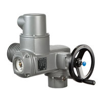
AUMA SG 12.1-F16 Operating Instructions Manual (80 pages)
Part-turn actuators. Control unit: electromechanic with actuator controls AUMATIC AC 01.1 Intrusive
Brand:
AUMA
| Category:
Controller
| Size: 1.8 MB
Table of Contents
Table of Contents
2
1 Safety Instructions
5
Basic Information on Safety
5
Range of Application
5
Applications in Ex Zone 22 (Option)
6
Warnings and Notes
6
References and Symbols
7
2 Identification
8
Name Plate
8
Short Description
9
3 Transport, Storage and Packaging
11
Transport
11
Storage
11
Packaging
11
4 Assembly
12
Mounting Position
12
Ball Handle: Fit to Handwheel
12
Part-Turn Actuator to Valve: Mount
12
Coupling
13
Mounting Positions of Local Controls
14
Mounting Positions: Modify
14
5 Electrical Connection
16
Basic Information
16
Connection with AUMA Plug/Socket Connector
18
Terminal Compartment: Open
18
Cable Connection
19
Terminal Compartment: Close
20
Bus Terminal Compartment: Open
20
Bus Cables: Connect
21
Bus Terminal Compartment: Close
24
Accessories for Electrical Connection
24
Controls Mounted to Wall Bracket
24
Parking Frame
25
Protection Cover
26
Double Sealed Intermediate Frame
26
Earth Connection, External
26
6 Operation
27
Manual Operation
27
Manual Operation: Engage
27
Manual Operation: Disengage
27
Motor Operation
27
Local Operation
27
Operation from REMOTE
28
Menu Navigation Via Push Buttons (for Settings and Indications)
29
Short Overview: Functions of the Push Buttons
29
Structural Design and Navigation
29
Password Entry
30
Language Change in the Display
31
7 Indications
33
Status Indications in the Display
33
Status Indication S0/S6 - Operation
33
Torque Indication: Edit
34
Indication Lights/Leds
34
Mechanical Position Indicator/Running Indication
35
8 Signals
36
Signals Via Fieldbus
36
Feedback Signals Via Output Contacts (Binary)
36
Feedback Signals (Analogue)
36
9 Commissioning (Basic Settings)
37
Heat-Up Time for Low Temperature Version
37
End Stops in Part-Turn Actuator
37
End Stop CLOSED: Set
38
End Stop OPEN: Set
39
Swing Angle
39
Swing Angle Modification
40
Type of Seating: Check/Edit for End Positions
41
Baud Rate, Parity and Bus Addres (Slave Addess): Set
44
Further Parameters of the Modbus Interface
47
Switch Compartment: Open
47
Torque Switching: Set
48
Limit Switching: Set
48
End Position CLOSED (Black Section): Set
49
End Position OPEN (White Section): Set
49
Intermediate Positions: Set
50
Running Direction CLOSE (Black Section): Set
50
Running Direction OPEN (White Section): Set
50
Test Run
51
Direction of Rotation: Check
51
Limit Switching: Check
51
Reference Operation Position Feedback: Perform
52
Potentiometer Setting
52
Electronic Position Transmitter RWG: Set
53
Mechanical Position Indicator: Set
53
Switch Compartment: Close
54
Operating Time: Set
54
Corrective Action
56
Faults During Commissioning
56
Fault Indications and Warning Indications
56
Status Indication S0 - Faults and Warnings
56
Status Indication S1 - Faults
57
Status Indication S2 - Warnings
58
Status Indication S3 - Causes for Not Ready Remote
59
Fuses
59
Fuses Within the Actuator Controls
59
Motor Protection (Thermal Monitoring)
60
Servicing and Maintenance
62
Preventive Measures for Servicing and Safe Operation
62
Maintenance
62
Disposal and Recycling
62
Technical Data
63
Features and Functions of Actuator
63
Features and Functions of Actuator Controls
64
Modbus Interface
67
Service Conditions
69
Accessories
69
Further Information
70
Spare Parts
71
Part-Turn Actuators SG 05.1 - SG 12.1/SGR 05.1 - SGR
71
Actuator Controls AUMATIC AC 01.1 with AUMA Plug/Socket Connector(SD Bus)
73
Certificates
75
Declaration of Incorporation and EC Declaration of Conformity
75
Index
76
Addresses
78
Advertisement
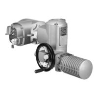
AUMA SG 12.1-F16 Operating Instructions Manual (68 pages)
Part-turn actuators SG series; SGR series. with actuators. Auma Matic AM 01.1
Brand:
AUMA
| Category:
Controller
| Size: 1.51 MB
Table of Contents
Table of Contents
2
1 Safety Instructions
5
Basic Information on Safety
5
Range of Application
5
Applications in Ex Zone 22 (Option)
6
Warnings and Notes
6
References and Symbols
7
2 Identification
8
Name Plate
8
Short Description
9
3 Transport, Storage and Packaging
10
Transport
10
Storage
10
Packaging
10
4 Assembly
11
Mounting Position
11
Ball Handle: Fit to Handwheel
11
Part-Turn Actuator to Valve: Mount
11
Coupling
12
Mounting Positions of Local Controls
13
Mounting Positions: Modify
13
5 Electrical Connection
15
Basic Information
15
Connection with AUMA Plug/Socket Connector
16
Terminal Compartment: Open
16
Cable Connection
17
Terminal Compartment: Close
19
Accessories for Electrical Connection
19
Controls Mounted to Wall Bracket
19
Parking Frame
20
Protection Cover
20
Double Sealed Intermediate Frame
20
6 Operation
21
Manual Operation
21
Manual Operation: Engage
21
Manual Operation: Disengage
21
Motor Operation
21
Local Operation
21
Actuator Operation from Remote
22
7 Indications
24
Indication Lights
24
Mechanical Position Indicator/Running Indication
24
8 Signals
26
Feedback Signals Via Output Contacts (Binary)
26
Feedback Signals (Analogue)
26
9 Commissioning (Basic Settings)
27
Heat-Up Time for Low Temperature Version
27
End Stops in Part-Turn Actuator
27
End Stop CLOSED: Set
28
End Stop OPEN: Set
29
Swing Angle
29
Swing Angle: Modify
30
Switch Compartment: Open
30
Torque Switching: Set
31
Limit Switching: Set
32
End Position CLOSED (Black Section): Set
32
End Position OPEN (White Section): Set
33
Intermediate Positions: Set
33
Running Direction CLOSE (Black Section): Set
34
Running Direction OPEN (White Section): Set
34
Test Run
34
Direction of Rotation: Check
34
Limit Switching: Check
35
PTC Tripping Device (Option): Test
35
Potentiometer Setting
36
Electronic Position Transmitter RWG: Set
36
Mechanical Position Indicator: Set
37
Switch Compartment: Close
38
Operating Time: Set
38
10 Commissioning
40
Controls: Open
40
Type of Seating: Set
40
Push-To-Run Operation or Self-Retaining: Set
41
Running Indication (Blinker Transmitter): Activate/Deactivate
42
Torque Fault in Collective Fault Signal: Activate/Deactivate
42
Positioner
42
Input Ranges (Signal Type) for Setpoint and Actual Value
43
Behaviour on Loss of Signal (Actuator Reaction)
43
Adjustment in End Positions
45
Sensitivity Setting
46
EMERGENCY Command (EMERGENCY - OPEN/EMERGENCY - CLOSE)
47
Sgr 12.1
47
Controls: Close
48
11 Corrective Action
49
Faults During Commissioning
49
Fuses
49
Fuses Within the Actuator Controls
49
Motor Protection (Thermal Monitoring)
50
12 Servicing and Maintenance
52
Preventive Measures for Servicing and Safe Operation
52
Maintenance
52
Disposal and Recycling
52
13 Technical Data
53
Features and Functions of Actuator
53
Features and Functions of Actuator Controls
54
Service Conditions
56
Further Information
57
Spare Parts
58
Part-Turn Actuators SG
58
Sg 12.1/Sgr 05.1
58
Actuator Controls AUMA MATIC am 01.1/AM
60
15 Certificates
62
Declaration of Incorporation and EC Declaration of Conformity
62
16 Index
63
Addresses
65
Advertisement
Related Products
AUMA SG 12.1-F12
AUMA SG 12.1-F14
AUMA SG 12.1-FA12
AUMA SG 10.1-F10
AUMA SG 10.1-F12
AUMA SG 10.1-FA12
AUMA SG 10.1
AUMA SG 10.2
AUMA SGR 05.1-F05
AUMA SGM 14.1
AUMA Categories
Controller
Industrial Equipment
Control Unit
Control Systems
Valve Positioners
More AUMA Manuals
Login
Sign In
OR
Sign in with Facebook
Sign in with Google
Upload manual
Upload from disk
Upload from URL