Dräger PIR 3000 Instructions For Use Manual
Infrared gas transmitter
Hide thumbs
Also See for PIR 3000:
- Instructions for use manual (48 pages) ,
- Installation instructions manual (13 pages) ,
- Instructions for use manual (48 pages)
Table of Contents
Advertisement
Advertisement
Table of Contents

Related Manuals for Dräger PIR 3000


Summary of Contents for Dräger PIR 3000
- Page 1 Dräger PIR 3000 Infrared Gas Transmitter Instructions for Use...
-
Page 2: Table Of Contents
Dräger PIR 3000 infrared gas transmitter ........ -
Page 3: For Your Safety
For Your Safety For Your Safety Strictly follow these Instructions for Use Any use of this gas transmitter requires full understanding of the information provided and strict adherence to the instructions given. The gas transmitter is only to be used for the purposes specified here. Maintenance Maintenance jobs may only be carried out by trained service personnel. -
Page 4: Intended Use
An analogue, 4 to 20 mA output signal is used as measuring value output. The Dräger PIR 3000 infrared gas transmitter is designed for use in rough ambient conditions and is suited for installation in hazardous areas of zones 1, 2, 21 and 22 according to the device categories 2G, 3G, 2D, 3D or Class I &... -
Page 5: Explosion-Protection Approvals
Explosion-Protection Approvals Explosion-Protection Approvals The explosion-protection approvals are valid for use of the device in gas/vapour-air mixtures of combustible gases and vapours under atmospheric conditions. The explosion-protection approvals are not valid for use in oxygen-enriched atmospheres. Unauthorised opening of the enclosure invalidates the explosion-protection approval. —... -
Page 6: Installing The Gas Transmitter
Installing the Gas Transmitter Only trained service personnel (e.g. of Dräger) may install the gas transmitter under observation of relevant regulations. Installation and commissioning are described in the "Dräger PIR 3000 Installation Instructions" which are supplied with the gas transmitter. Mounting Location The protecting effect of the gas transmitter depends on the selection of the mounting location. -
Page 7: Gas Exposure / Process Adapter (See "Accessories/Spare Parts
Installing the Gas Transmitter The splash guard is held by a fixture provided with screw-thread, which is also used as calibration adapter. Make sure that the calibration adapter is correctly seated. To this end, manually tighten the calibration adapter to a point where the sealing line leaves a permanent mark on the splash guard. -
Page 8: Electrical Installation
Installing the Gas Transmitter Electrical Installation NOTICE If present: If the connector of the gas transmitter is not required, it must be removed prior to the electrical installation. To do so, cut the cables with a suitable tool directly in front of the connector, strip the insulation, and attach suitable ferrules. The entire wiring must correspond with applicable local regulations concerning the installation of electrical devices in potentially explosive atmospheres. -
Page 9: When Used According To Bvs 05 Atex E 143 X, Please Note
Installing the Gas Transmitter — The leads between central device and gas transmitter must have a sufficiently low resistance to ensure the correct supply voltage at the gas transmitter. The maximum resistance per core is calculated as follows: 2.5 x U –... -
Page 10: Commissioning
Installing the Gas Transmitter Commissioning The Dräger PIR 3000 infrared gas transmitter is preconfigured and ready for use after installation. Deactivate the alarm call to the central device to avoid false alarms. When the supply voltage is applied, the gas transmitter automatically performs a self check (10 seconds), then automatically uses the factory-preset calibration (see page 11) and gas category. -
Page 11: Operational Characteristics
Zero gas and test gas are to be applied for functional check and calibration of the infrared gas transmitter Dräger PIR 3000. To this end, the gas is applied either with — the calibration adapter in connection with the splash guard (see page 5, part of the scope of delivery) or —... - Page 12 (methane, propane, ethylene). The highest accuracy is achieved using test gas concentrations of 40 to 70 percent of the measurement span. The infrared gas transmitter Dräger PIR 3000 can also be used to measure other gases than mentioned above. For detailed information, refer to "Substitute Gas Calibration"...
-
Page 13: Configuration Of The Gas Transmitter Via Magnetic Pin
Operational Characteristics Configuration of the Gas Transmitter via Magnetic Pin A magnetic pin can be used to change the settings of the Dräger PIR 3000 infrared gas transmitter (see "Accessories/Spare parts" on page 27) as follows: — Automatic zerosetting. — Manual zero calibration of the output signal. -
Page 14: Manual Zero Calibration Of The Output Signal
Operational Characteristics Manual Zero Calibration of the Output Signal. Deactivate alarm activation of the central device. 1 Expose the gas transmitter to nitrogen, synthetic air, and/or fresh air via calibra- tion adapter and wait until measurement value stabilises. 2 Place the magnetic pin onto the transmitter surface area marked by the " "... -
Page 15: Manual Span Calibration Of The Output Signal
Operational Characteristics Manual Span Calibration of the Output Signal. The span calibration of the gas transmitter is only possible under the following conditions: — The last zero calibration of the device was less than one hour ago. — The span gas concentration is sufficiently high to effect a display on the device of at least approx. -
Page 16: Substitute Gas Calibration
Operational Characteristics Substitute Gas Calibration The infrared gas transmitter Dräger PIR 3000 can also be used to measure other gases and vapours. The following table shows the required information (see also "Calibration" on page 11). Measured gas CAS-No. Measuring range... -
Page 17: Checking The Signal Transmission, Checking The Alarm Trigger And Displaying The Gas Category
Operational Characteristics Checking the Signal Transmission, Checking the Alarm Trigger and Display- ing the Gas Category The gas transmitter can create an output signal of 80 % of the full scale value, even without exposure to test gas. This 80% signal can be used to —... -
Page 18: Changing The Gas Category
Operational Characteristics — This signal is maintained for 30 seconds. The gas transmitter will then switch back to normal operation. — The central device display now matches the output signal of the gas transmitter. Reactivate alarm activation of the central device. NOTICE Using the 80% signal to match central device and transmitter signal without test gas is no replacement for the span calibration of the gas warning system. - Page 19 Operational Characteristics Remove the magnetic pin. The gas transmitter changes to an output signal which displays the currently set gas category according to the following table: Gas category Display [%LEL] methane propane 10.4 ethylene 13.6 This signal is maintained for 30 seconds. Within this period of time, the magnetic pin can be placed upon the area marked by the "...
-
Page 20: Maintenance
Maintenance Maintenance Regular intervals are to be determined for the following tasks by the persons responsible for the gas warning system while taking local regulations into account: Visual inspection to look for damage and contamination. Special attention is required for gas entrance to the gas transmitter. Anything that blocks the gas entrance to the transmitter, e.g. -
Page 21: Faults, Cause And Remedy
Faults, Cause and Remedy Faults, Cause and Remedy Fault Cause Remedy No output signal Gas transmitter is not powered up Check power supply and polarity. Gas transmitter defective Have Dräger check the gas transmitter. Transmitter output signal and central Central device and gas transmitter are Match central device and gas device display do not match not matched... -
Page 22: Technical Data
Technical Data Technical Data General Details Functional Principle Compensated Infrared Absorption Standard operating range 0 – 100 %LEL Standard sensitivity 0.16 mA/%LEL Standard gas categories methane, propane, ethylene Output signal 4 to 20 mA Power supply 10 to 30 V DC Switch-on current (2 ms) ≤0.5 A Power consumption... -
Page 23: Measuring Technique Characteristics
Technical Data Measuring Technique Characteristics digital resolution of measurement values 0±0.5 %LEL repeatability ≤ ±2 %LEL linearity error ≤ ±5 %LEL temperature influence, –40 to 65 °C zero point ≤ ±3 %LEL span (rel. change of display at 50 %LEL) ≤... -
Page 24: Cross Sensitivities
Technical Data Cross Sensitivities The gas transmitter measures the concentration of hydrocarbons. Factory-preset calibration parameters are available for methane, propane and ethylene gases. However, other hydrocarbons can also be measured. The following text has examples of typical display values for some types of hydrocarbon, with the gas transmitter calibrated in the respectively stated gas category. -
Page 25: Dimensions
Technical Data Dimensions M25 x 1.5 3/4" NPT ø 37 mm... -
Page 26: Description Of Design
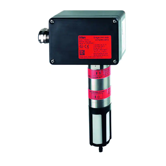
Description of Design Description of Design The Dräger PIR 3000 infrared gas transmitter is a gas transmitter designed to determine the concentration of gases and vapours in the ambient air. The principle of measurement is based on the concentration-dependent absorption of infrared radiation in measured gases. -
Page 27: Order List
3/4" NPT, type IDS 0001 Dräger PIR 3000 compl. set d 68 11 180 connecting thread 3/4" NPT, type ITR 0010 Dräger PIR 3000 compl. set d CCCF 68 12 505 connecting thread 3/4" NPT, type ITR 0010 Dräger PIR 3000 68 10 810 connecting thread M 25 x 1.5, type IDS 0011... -
Page 28: Atex - Approval
ATEX - Approval ATEX - Approval... - Page 29 ATEX - Approval...
- Page 30 ATEX - Approval...
- Page 31 ATEX - Approval...
- Page 32 ATEX - Approval...
- Page 33 ATEX - Approval...
- Page 34 ATEX - Approval...
- Page 35 ATEX - Approval...
- Page 36 ATEX - Approval...
- Page 37 ATEX - Approval...
- Page 38 ATEX - Approval...
- Page 39 ATEX - Approval...
- Page 40 ATEX - Approval...
- Page 41 ATEX - Approval...
- Page 42 ATEX - Approval...
- Page 43 ATEX - Approval...
- Page 44 ATEX - Approval...
- Page 45 ATEX - Approval...
- Page 46 ATEX - Approval...
- Page 47 ATEX - Approval...
-
Page 48: Iecex - Approval
IECEx - Approval IECEx - Approval... - Page 49 IECEx - Approval...
- Page 50 IECEx - Approval...
- Page 51 IECEx - Approval...
- Page 52 IECEx - Approval...
- Page 53 IECEx - Approval...
-
Page 54: Ul - Approval
UL - Approval UL - Approval... - Page 55 UL - Approval...
- Page 56 UL - Approval...
-
Page 57: Csa - Approval
CSA - Approval CSA - Approval... - Page 58 CSA - Approval...
- Page 59 CSA - Approval...
-
Page 60: Declaration Of Conformity
Declaration of Conformity Declaration of Conformity... - Page 64 Dräger Safety AG & Co. KGaA Revalstraße 1 D-23560 Lübeck Germany Phone +49 451 8 82 - 27 94 Telefax +49 451 8 82 - 49 91 www.draeger.com 90 23 974 - GA 4677.500 en © Dräger Safety AG & Co. KGaA Edition 10 - February 2016 (Edition 01 - December 2005) Subject to alteration...
Need help?
Do you have a question about the PIR 3000 and is the answer not in the manual?
Questions and answers