
Subscribe to Our Youtube Channel
Related Manuals for Dräger P7-TD


Summary of Contents for Dräger P7-TD
- Page 1 Instruction Manual Dräger P7-TD Dräger MSI GmbH Rohrstraße 32 58093 Hagen Tel.: +49 (0) 2331 95 84 0 Fax: +49 (0) 2331 95 84 29 email: msi.info@draeger.com 5695075 Edition 02 – January 2019 (Edition 01 – June 2017)
-
Page 2: Table Of Contents
9.2 Selection of the gas pipeline test ................11 9.3 Assessment of serviceability according to TRGI G 600 and G 5952 ......12 9.3.1 General information regarding leak rate measurement using the MSI P7-TD ..12 9.3.2 Preparing the leak rate measurement ..............13 ... - Page 3 Instruction Manual Dräger P7-TD 12.1 Tightness and stress tests ..................23 12.2 Termination or cancellation of pipeline tests ............24 13. Data storage ........................ 24 13.1 Storing measurements .................... 24 13.2 Data management functions ................... 25 ...
-
Page 4: Tips
1. Tips 1.1 Approvals The pressure and leak rate measuring device Dräger P7-TD is tested and approved by the “Deutscher Verein des Gas- und Wasserfaches” (DVGW - German Association for Gas and Water) and approved under the registration number DG-4805BS0029. -
Page 5: The Measuring Device
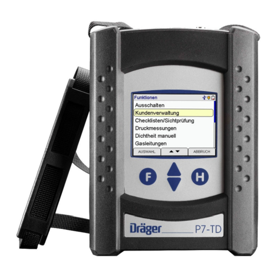
Instruction Manual Dräger P7-TD 2. The measuring device The P7-TD is an electronic multi-channel measuring device. It enables various inspections of pipelines and containers filled with gases, air or water. All inspections and measurements can be documented by means of printouts or storage. -
Page 6: Operation
The assignment of the functions keys is shown in the last line on the display re- spectively. The P7-TD has a touch screen. Touching the display in the relevant spot replaces the command executed with the key. You can scroll the displayed content by dragging your finger in a specific direction on the screen. -
Page 7: Info Window And Help Functions
Instruction Manual Dräger P7-TD A context menu is opened with (lll). Depending on the menu item, the context menu offers vari- ous editing options and commands. A previously selected customer number is shown in the result display with (REF). The cus- tomer number can be changed before storing. -
Page 8: Results Display
Instruction Manual Dräger P7-TD 3.3 Results display A result display appears after completing a measurement. You can scroll through the result display using (▲▼) A reference dataset is shown using . It consists of a cus- (REF) tomer dataset selected prior to the measurement and the se- lected tester. -
Page 9: Selecting And Entering Customer Data
Instruction Manual Dräger P7-TD 5. Selecting and entering customer data Using the PC software, there is the option of creating a cus- tomer number, customer name and customer data and transmitting this information to the measuring device. If customer data is stored in the device, this function can be used to select a customer and store data measurements un- der this customer’s name. -
Page 10: Checklists / Visual Inspection
Instruction Manual Dräger P7-TD 6. Checklists / Visual inspection A comment can be added to the results of the visual inspec- tion and be documented. Checklists can be configured using the professional software PC200P. Up to 4 different checklists each with up to 20 items can be stored, edited and documented on the device. -
Page 11: Conducting Pressure Measurements
Instruction Manual Dräger P7-TD 7.2 Conducting pressure measurements Connect the test nipple on the pressure tank or pressure line to be measured to the corresponding pressure inlet of the measuring device using a pressure hose. For high pressure measurements, connect the pressure tank or line to be measured to the external high pressure sensor using an adapter. -
Page 12: Manual Tightness Test
Instruction Manual Dräger P7-TD 8. Manual tightness test Test pressure, Stable time and measurement period can be set during the manual tightness test. Select measuring channel: 150, 1,000 or 25,000 hPa (mbar). Select test pressure: 10 - 150 hPa (mbar), 100 - 1,000 hPa (mbar) or 1,000 - 25,000 hPa (mbar). -
Page 13: Assessment Of Serviceability According To Trgi G 600 And G 5952
4 weeks. 9.3.1 General information regarding leak rate measurement using the MSI P7-TD The MSI P7-TD enables determining the serviceability of gas pipelines according to TRGI G 600 and test basis G 5952 at operating pressure. This method (comparison leak meth- od) is patented. -
Page 14: Preparing The Leak Rate Measurement
Instruction Manual Dräger P7-TD 9.3.2 Preparing the leak rate measurement Select standard leak measurement or leak measurement with regulator in line. The quick test and the measurement for expanded volume are not DVGW (German competence network for all ques- tions related to gas and water supply) tested and cannot be stored. -
Page 15: Stabilization
Instruction Manual Dräger P7-TD 9.3.3 Stabilization The stabilization of the gas pressure takes approx. 2 to 10 min. The current pressure in the gas pipeline to be tested, the already elapsed time of the stabilization period and the pres- sure drop up to this point (negative values mean that the pressure in the gas pipeline has increased, e.g. -
Page 16: Tightness Tests According To Dvgw Trgi 2018 Process Sheet G 600
(line sections) to be tested. 9.4.1 Automatic tightness test The P7-TD enables a direct selection and an automatic iden- tification of the gas pipeline volume. The automatic identification of the gas pipeline volume can... -
Page 17: Tightness Test With External Pump Acc. To Dvgw Trgi Process Sheet G 600
9.4.2 Tightness test with external pump acc. to DVGW TRGI process sheet G 600 The flow rate of the P7-TD pump is approx. 1 l/min. The pressure increase to 100 hPa (mbar) for a gas pipeline volume of 100 l takes approx. 15 min. Therefore, it makes sense to work with an external pump, to shorten the time for pressure increase. -
Page 18: Stress Test Acc. To Dvgw Trgi Process Sheet G 600
Instruction Manual Dräger P7-TD 9.5 Stress test acc. to DVGW TRGI process sheet G 600 9.5.1 Regulations for low pressure systems A stress test must be conducted prior to the tightness test for gas installations for new low pressure systems (operating pressure < 100 hPa (mbar)). -
Page 19: Testing Drinking Water Installations
Instruction Manual Dräger P7-TD 10. Testing drinking water installations According to DIN EN 806-4, the tests required for drinking water installations can either be conducted using water or with air or inert gas. Tests for drinking water installations with water can only be conducted with an optional external high pressure sensor. -
Page 20: Tightness Test With External Pump
The duration of the stabilization phase for temperature equalization is not specified; the P7-TD defines the duration depending on the pressure stability in the pipeline (2 to 10 min). A measurement period of 10 minutes is required for the measurement. -
Page 21: Tightness Tests For Drinking Water Installations Using Water
Instruction Manual Dräger P7-TD 10.2 Tightness tests for drinking water installations using water Tests for drinking water installations with water can only be conducted with an op- tional external high pressure sensor. If tests are conducted using the internal pres-... -
Page 22: Metal, Multi-Layer Composite And Pvc Pipes
Instruction Manual Dräger P7-TD 10.2.2 Metal, multi-layer composite and PVC pipes A stabilization period for temperature equalization amounting to 10 min and a test time of 30 min must be complied with for the tightness testing of drinking water installations using wa- ter, which consist of metal, multi-layer composites and PVC pipes. - Page 23 Instruction Manual Dräger P7-TD Connect the pressure sensor to the pipeline to be tested and start the measurement. Connect the external pump to the pipeline using a valve and increase the pressure. Start the stabilization phase. Maintain the test pressure during the stabilization phase.
-
Page 24: Conducting Pipeline Tests
Instruction Manual Dräger P7-TD 12. Conducting pipeline tests 12.1 Tightness and stress tests During pipeline tests, an informational text provides information pertaining to the current measurement process. After pumping up to the respective test pressure (not for external pumps), the device checks the pressure for 1 minute. -
Page 25: Termination Or Cancellation Of Pipeline Tests
Instruction Manual Dräger P7-TD 12.2 Termination or cancellation of pipeline tests If a pipeline test was terminated or cancelled, the measuring device gives the instruction to close the valve on the connect- ing nipple of the measuring point and remove the hose on the pressure probe from the pipeline being tested. -
Page 26: Data Management Functions
Instruction Manual Dräger P7-TD All measurements are stored together with date and time us- ing ( ) “New dataset”. STORE If an already existing dataset was selected, the dataset can be overwritten. 13.2 Data management functions The following functions can be selected:... -
Page 27: Deleting Measurement Data
14. Information function The display provides information regarding the measuring device type (MSI P7-TD), the manufacturer (Dräger MSI GmbH), the version of the measuring device software (here 3.0,005), the serial number of the measuring device, the next servicing date and date and time of accessing the information function. -
Page 28: Configuration
Instruction Manual Dräger P7-TD 15. Configuration The measuring device can be configured according to the user’s requirements. The following functions can be selected: Clock = set date and time Leak Auto Start = activation of the automatic start for leak rate measurement... -
Page 29: Selection Of The Damping Value For The Pressure Sensor
Instruction Manual Dräger P7-TD 15.3 Selection of the damping value for the pressure sensor The damping value for the pressure sensor can be changed for a normal pressure measurement. The following damping values can be selected: = no damping MEDIUM... -
Page 30: Printer
Instruction Manual Dräger P7-TD 15.7 Printer The MSI IR3 printer or the HP printer can be selected using ▲▼ MSI IR3 printer: Data transmission and printing rates are now faster than with HP protocol compatible printers. HP printer: Data transmission corresponds to the HP protocol and is suitable for all HP protocol compatible printers;... -
Page 31: Deleting An Individual Measurement
Instruction Manual Dräger P7-TD 15.10 Deleting an individual measurement This function enables deleting an individual measurement dataset. 15.11 Language Text on the display can be shown in German and English. 15.12 Switching pressure units This function allows switching the pressure units. Changing the pressure unit is applied to all measurements. -
Page 32: Function Assistance, Warnings And Error Messages
Instruction Manual Dräger P7-TD 16. Function assistance, warnings and error messages 16.1 Function assistance - symbols A number of function symbols are shown on the right side of the display. The following symbols can be shown: Battery charging Capacity of the battery... -
Page 33: Warnings And Error Messages
Instruction Manual Dräger P7-TD 16.2 Warnings and error messages The measuring device checks the proper functioning of all measuring channels during the activation phase and during measurement operation. Warnings and error messages are shown after the start-up phase or during normal functioning. -
Page 34: High Performance Rechargeable Battery
Instruction Manual Dräger P7-TD 17. High performance rechargeable battery 17.1 General information regarding the power supply A high performance rechargeable nickel metal hydride battery installed in the measuring device enables network-independent operation. The operating time with a fully charged battery is normally more than 8 hours; however, this can vary depending on the type of measurements. -
Page 35: Technical Specifications
Instruction Manual Dräger P7-TD 18. Technical specifications 18.1 General technical specifications Approvals: type test DVGW, registration number: DG-4805BS0029 Display: colour display with touchscreen Interfaces: USB, IR Power supply: NI-MH Battery, 4.8 V, 2000 mAh, charge level indicator, Charger primary 230 V; secondary 12 V; 0.8 A... -
Page 36: Technical Specifications Pipeline Tests
Instruction Manual Dräger P7-TD 18.3 Technical specifications pipeline tests Serviceability test: Leak rate measuring range 0 to 10 liter/h resolution 0.01 liter/h Volume measuring range 1 to 300 liters resolution 0.1 liter Medium pressure measuring range 10 ... + 100 hPa (mbar) resolution 0.01 hPa (mbar)
Need help?
Do you have a question about the P7-TD and is the answer not in the manual?
Questions and answers