Table of Contents
Advertisement
Product Manual
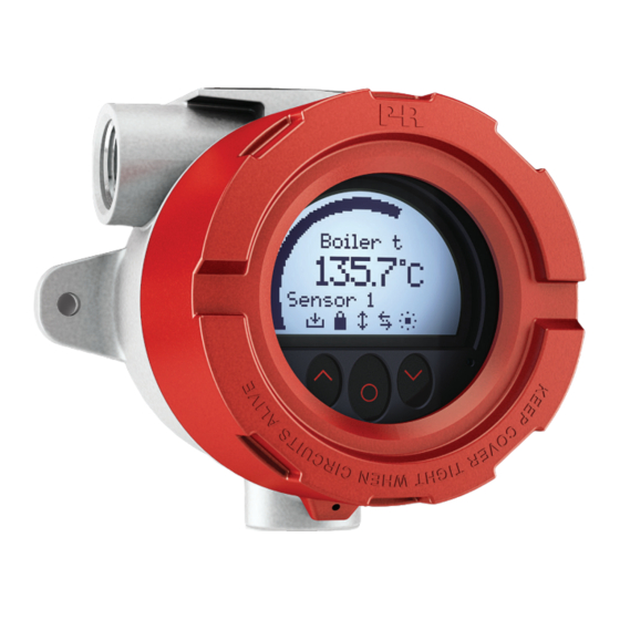
7501
Field mounted HART
temperature transmitter
T E M P E R AT U R E
|
I . S . I N T E R FA C E S
No. 7501V107- UK
S erial no. : 170 8 070 01-170 816 075
|
CO M M U N I C AT I O N I N T E R FA C E S
|
M U LT I F U N C T I O N A L
|
I S O L AT I O N
PERFORMANCE
MADE
SMARTER
|
D I S P L AY
Advertisement
Table of Contents

Related Manuals for PR electronics 7501


Summary of Contents for PR electronics 7501
- Page 1 PERFORMANCE MADE SMARTER Product Manual 7501 Field mounted HART temperature transmitter T E M P E R AT U R E I . S . I N T E R FA C E S CO M M U N I C AT I O N I N T E R FA C E S...
- Page 2 6 Product Pillars to meet your every need Individually outstanding, unrivalled in combination With our innovative, patented technologies, we make signal conditioning smarter and simpler. Our portfolio is composed of six product areas, where we offer a wide range of analog and digital devices covering over a thousand applications in industrial and factory automation.
-
Page 3: Table Of Contents
Field mounted HART temperature transmitter 7501 Table of contents Warning .................... -
Page 4: Warning
Mounting and connection of the device should comply with national legislation for mounting of electric materials. Repair of the device must be done by PR electronics A/S only. Do not remove the transmitter cover in explosive atmospheres when the circuit is live. -
Page 5: Applications
Field mounted HART temperature transmitter 7501 • RTD, TC, Ohm, and bipolar mV input and analog output • High definition local operator interface (LOI) with 3 optical buttons • Selectable red or white backlight • Ex d explosion proof / flameproof in aluminum or 316 stainless steel version •... -
Page 6: Order
= 7501 M20 plug text alu encl. silicone O-ring 8550-F = 7501 M20 plug text alu encl. FKM O-ring 8550-S = 7501 M20 plug text stainless steel encl. silicone O-ring 8550-SF = 7501 M20 plug text stainless steel encl. FKM O-ring 8551 = 7501 NPT plug alu encl. - Page 7 Isolation - test / working ....... 1.5 kVAC / 50 VAC Signal / noise ratio .
- Page 8 TC input types: Min. Max. Min. Type temperature temperature span Standard 0°C +1820°C 100°C IEC584 -100°C +1000°C 50°C IEC584 -100°C +1200°C 50°C IEC584 +1372°C 50°C IEC584 -180°C -200°C +900°C 50°C DIN 43710 -200°C +800°C 50°C GOST 3044-84 -180°C +1300°C 50°C IEC584 -50°C +1760°C...
-
Page 9: Block Diagram
Block diagram 7501 Display DOWN ENTER 5337 HART Sensor 4...20 mA transmitter Supply Application + HART 4...20 mA HART + HART HART HART HART HART Filter HART modem slave “master” modem 8 V / 4...20 mA Marking When this product has been installed as Ex... -
Page 10: Mechanical Specifications
Mechanical specifications It is important to be careful when screwing the cover on or off. The thread surface must be free of any grains, pellets or other impurities as these can cause the cover to seize or damage the threads. ! Never use force to screw on the cover. - Page 11 Side view AL: 109.3 RF: 107.4 AL: 25 / RF: 24 AL: 7 RF: 6 AL: 35 RF: 34 7501V107-UK...
-
Page 12: Mounting
Mounting Wall-mounting – side view Wall-mounting – top view 2 x Ø 7 7501V107-UK... - Page 13 Pipe-mounting – front and back view Pipe-mounting – top view 7501V107-UK...
-
Page 14: Protection Degree
Protection degree is defined by the connection with the lowest IP rating. It is optional to connect a sensor to any of the three conduit openings. Blind plugs are Ex approved only when used together with 7501. Earth terminal and protection terminal... -
Page 15: Assembly And Disassembly
Assembly and disassembly To connect sensor wires to the 7501 or change the orientation of the display, the housing must be disassembled and the internal device must be extracted. !! Disconnect power to the device before disassembly. Locking screw 1. Release the locking screw, using a hex spanner with a cross-flat of 2 [mm]. This screw is situated on the housing top. - Page 16 4. While holding the clamps, pull the display unit outwards to remove it. 5. The display can now be turned in steps of 90 degrees for best viewing angle. 6. For easy connection of sensor wires, we recommend extracting the transmitter from the housing (see the section Connections for information on connecting sensors to the internal 5337).
- Page 17 9. Use a screwdriver (or your fingers) to lever the taps (one on each side) on the fixation bracket to release it from the transmitter connector bracket. NB! Do not use excessive force. 10. Separate the connector bracket, transmitter and fixation bracket. 7501V107-UK...
- Page 18 Assembly 1. Place the transmitter in the fixation bracket using the guidance taps on the bracket. Make sure terminals 1 and 2 are facing downwards. NB. The fixation bracket is not interchangeable between the aluminum and stainless steel housing. Check the bottom right-hand corner for identifier (Al for aluminum and RF for stainless steel).
- Page 19 3. Slide the assembly back into the housing and refasten the 4 screws (a + b), using the 28 mm screws for the connector bracket (a) and the 10 mm screws for the fixation bracket (b). 4. Finally, click the display unit back into place and screw the cover back on. Correct mounting of display unit ...
-
Page 20: Connections
Connections Input: RTD, 2-wire RTD, 3-wire RTD, 4-wire TC, internal CJC Resistance, 3-wire TC, external CJC Resistance, 2-wire TC, di erence TC, di erence or average, or average, RTD, di erence Resistance, 4-wire or average with internal CJC with external CJC Output: mV, di erence or average... -
Page 21: Optical Buttons
Display views The appearance of the display will change to reflect the state of the 7501. This allows for easy and intuitive operation, status indication and guides you in configuring the device. Dark colored gloves can cause reduced sensitivity. - Page 22 Symbol identification The symbols bar provides information on the state of the device. Information such as HART communication, write protection and process value tendency is shown. Saving configuration to internal memory Device is locked or write-protected Current process value tendency indicators External HART communication indicator Internal communication indicator External HART communication error...
- Page 23 Configuration When configuring the 7501, you will be guided through all parameters and you can choose the settings which fit the application. For each menu there is a scrolling help text which is automatically shown in the display. Configuration is carried out by use of the three optical buttons.
-
Page 24: Device And Sensor Status Indication
Device and sensor status indication The 7501 is capable of displaying diagnostics information for the sensors and the device. These diagnostics can be divided into 4 categories: Sensor status, sensor errors, device status and device errors. Sensor status Sensor 1 exceeds upper sensor limit IN.HI... -
Page 25: Display Menu
The menu can be temporarily locked because it is receiving a configuration on the HART interface or because it is synchronizing configuration parameters with the internal device. If the 7501 has been write-protected it is still possible to proceed to the menu, but no changes can be made, and it is not possible to save the configuration. -
Page 26: Basic Configuration
Basic configuration Voltage 2-wire If connection is 3- or 4-wire, the max. cable 100.0 100.0 Single Sens Linear Res 3-wire resistance is set to 10 Ohm. Dual Sens Temperature 4-wire This can be overwritten in the Advanced Menu. 2 ... - Page 27 -40.0 -200 -200 -200 kOhm 135.0 2 2 2 2 2 Lin. R Unit Fix CJC val Max Diff Output Low Output High Txt 5 Txt 12 Txt 15 Txt 21 Txt 22 Voltage 2 Unit Txt 5 °C...
-
Page 28: Display
Display Sensor 1 Sensor 2 CJC Sensor Average Differential Loop Curr 9999 Loop Curr White White % Range % Range 0000 2 2 2 2 2 2 2 White White % Range Sensor 2 0000 “Monitor”... -
Page 29: Calibration
Calibration (only if Write-protection is disabled) The device can be process-calibrated in two points to fit a given input signal. A low input signal (not necessarily 0%) is applied and the actual value is entered. Secondly a high input signal (not necessarily 100%) is applied and the actual value is entered. If you accept to use the calibration (by selecting Yes in the Save menu) the device will work according to the new adjustments. -
Page 30: Simulation
(only if Write-protection is disabled) The 7501 allows you to simulate process values by entering the simulation menu. Using the and 2 optical buttons, the simulated value can be increased and decreased (see the section Operating the optical buttons). Please note that while performing a calibration the display will not time out. -
Page 31: Sensor
Sensor The sensor menu allows you to make more detailed configuration of your sensor values, which are not available in the basic configuration menu. These involve selecting from a large amount of process variable units, changing the sensor assignment to PV, SV, TV and QV and specifying the CJC response time. -
Page 32: Write-Protect
Save menu. Please note that changing the HART revision will reboot the device, during which time the display may become blank for a few seconds. If HART 7 is selected the device will appear as 7501 in the HART interface. -
Page 33: Help Text Overview
Help text overview [01] Set correct password [20] Map sensor1 to QV Map sensor2 to QV [02] Enter Advanced setup menu? Map CJC sensor to QV [03] Select single sensor functionality Select dual sensor functionality Map Internal temperature to QV Enter Display setup Map Avg measument to QV [04]... - Page 34 [76] Set menu access PIN-code [53] Enter sensor1 calibration menu [77] Set menu access PIN-code (0000 will disable) Enter sensor2 calibration menu Enter CJC sensor calibration menu [100] Enter output loop current calibration menu SW.ER Exception error during code execution [54] Reset calibration to factory default Flash memory error...
- Page 35 Available units The following table lists the available units. Please note that most of these are only available from the Sensor menu (see the section Display menu). Menu # HART # Text Types Menu # HART # Text Types °C <- Sensor specific types <- Volume units °F...
- Page 36 Menu # HART # Text Types µg/m <- Viscosity units <- Energy (work) units kW/h Mcal <- Power units MJ/h Btu/h deg/s <- Angular velocity units rev/s <- Miscellaneous µMho mS/cm µS/cm Vol% ml/l µl/l %LEL <blank>* <- Special units Spcl *No characters shown 7501V107-UK...
-
Page 37: Programming
For programming please refer to the drawing below. To get access to product-specific commands, the HART communicator must be loaded with the 7501 H5 / 7501 H7 DD driver. This can be ordered either from the HART Communication Foundation or from PR electronics. -
Page 38: Changing The Hart Protocol Version
Changing the HART revision using the PReset software Select either 7501H5 or 7501H7 depending on which protocol revision the 7501 is currently running. Click on the HART tab and then on Device Password / Write Protection / Protocol…. In the newly opened window check the “Change protocol to HART #”... - Page 39 (HART 7) or 60 mA (HART 5). The communication is done by means of either a HART communicator or a HART modem. The PReset configuration software can configure the individual transmitter for multidrop mode and provide it with a unique polling address. 7501 7501 7501 Power supply Max.
-
Page 40: Retrofit
For Ex installation the customer must assure that the installed transmitter has all the necessary approvals applicable for the place of installation. Once a 5335 / 5337 unit which has been fitted into the 7501, it must not be taken out and used in other applications. UNLESS O... -
Page 41: Appendix
Appendix ATEX Installation Drawing IECEx installation drawing FM Installation Drawing CSA Installation Drawing Desenho de Instalaçao INMETRO 7501V107-UK... -
Page 42: Atex Installation Drawing
WWW.PRELECTRONICS.COM 7501 ATEX Installation For safe installation of 7501 the following must be observed. The module shall only be installed by qualified personnel who are familiar with the national and international laws, directives and standards (EN60079-14) that apply to this area. - Page 43 7501QA01 LERBAKKEN 10, 8410 RØNDE DENMARK. WWW.PRELECTRONICS.COM Ex ia installation General installation instructions The sensor circuit is not infallibly galvanic isolated from the supply output circuit. However, the galvanic isolation between the circuits is capable of withstanding a test voltage of 500Vac during 1 minute.
- Page 44 O-ring Sealing : FKM T4: -20 ≤ Ta ≤ 85ºC (7501A ) T4: -20 ≤ Ta ≤ 80ºC (7501B ) T6: -20 ≤ Ta ≤ 60ºC Hazardous area Non Hazardous Area Zone 2, 22 7501 Supply Sensor Supply Supply Terminal: 3,4,5,6 Terminal: 1,2...
- Page 45 7501QA01 LERBAKKEN 10, 8410 RØNDE DENMARK. WWW.PRELECTRONICS.COM Ex nA, ic installation: For an ambient temperature exceeding 70 °C, heat resistant cables and cable glands suitable for at least 90°C shall be used. If the transmitter is physically connected to a possible source of heating or cooling, e.g. by mounting to a process pipe or a temperature sensor, the temperature at the point of connection shall be within the ambient temperature range as given in the certificate.
- Page 46 -20 ≤ Ta ≤ 85ºC T100°C (7501A ) -20 ≤ Ta ≤ 80ºC T100°C (7501B ) -20 ≤ Ta ≤ 70ºC T85°C Hazardous area Non Hazardous Area Zone 1, 2, 21, 22 7501 Supply Terminal: 1,2 Terminal: 3,4,5,6 Umax: 35 VDC Sensor: RTD or TC...
- Page 47 The sensor shall be suitable for use as entry device on an Ex d enclosure and shall not add volume to the 7501 enclosure. The thread of the sensor must be in compliance with EN60079-1 / EN60079-31.
-
Page 48: Iecex Installation Drawing
WWW.PRELECTRONICS.COM 7501 IECEx Installation For safe installation of 7501 the following must be observed. The module shall only be installed by qualified personnel who are familiar with the national and international laws, directives and standards (IEC60079-14) that apply to this area. - Page 49 7501QI01 LERBAKKEN 10, 8410 RØNDE DENMARK. WWW.PRELECTRONICS.COM Ex ia installation General installation instructions The sensor circuit is not infallibly galvanic isolated from the supply output circuit. However, the galvanic isolation between the circuits is capable of withstanding a test voltage of 500Vac during 1 minute.
- Page 50 O-ring Sealing : FKM T4: -20 ≤ Ta ≤ 85ºC (7501A ) T4: -20 ≤ Ta ≤ 80ºC (7501B ) T6: -20 ≤ Ta ≤ 60ºC Hazardous area Non Hazardous Area Zone 2, 22 7501 Supply Sensor Supply Supply Terminal: 3,4,5,6 Terminal: 1,2...
- Page 51 7501QI01 LERBAKKEN 10, 8410 RØNDE DENMARK. WWW.PRELECTRONICS.COM Ex nA, ic installation: For an ambient temperature exceeding 70°C, heat resistant cables and cable glands suitable for at least 90°C shall be used. If the transmitter is physically connected to a possible source of heating or cooling, e.g. by mounting to a process pipe or a temperature sensor, the temperature at the point of connection shall be within the ambient temperature range as given in the certificate.
- Page 52 -20 ≤ Ta ≤ 85ºC T100°C (7501A ) -20 ≤ Ta ≤ 80ºC T100°C (7501B ) -20 ≤ Ta ≤ 70ºC T85°C Hazardous area Non Hazardous Area Zone 1, 2, 21, 22 7501 Supply Terminal: 1,2 Terminal: 3,4,5,6 Umax: 35 VDC Sensor: RTD or TC...
- Page 53 The sensor shall be suitable for use as entry device on an Ex d enclosure and shall not add volume to the 7501 enclosure. The thread of the sensor must be in compliance...
-
Page 54: Fm Installation Drawing
WWW.PRELECTRONICS.COM FM Installation drawing 7501 For safe installation of 7501 the following must be observed. The module shall only be installed by qualified personnel who are familiar with the national and international laws, directives and standards that apply to this area. - Page 55 7501QF01 LERBAKKEN 10, 8410 RØNDE DENMARK. WWW.PRELECTRONICS.COM The entity concept The Transmitter must be installed according to National Electrical Code (ANSI-NFPA 70) and shall be installed with the enclosure, mounting, and spacing segregation requirement of the ultimate application. Equipment that is FM-approved for intrinsic safety may be connected to barriers based on the ENTITY CONCEPT.
- Page 56 Non classified Location Class I,II,III ,Division 2, Groups, ABCDFG Class I, Zone 2, IIC T4: -20/-40 ≤ Ta ≤ 85ºC T6: -20/-40 ≤ Ta ≤ 60ºC Vmax 7501 Terminal: 1,2 Terminal: 3,4,5,6 Vmax: 35 VDC Sensor: RTD or TC ...
- Page 57 Class I, II, III Division 1, Groups ABCDEFG Class I Zone 1, Ex/AEx d IIC T6 -20 /-40 ≤ Ta ≤ 70ºC T5, T4: -20 /-40 ≤ Ta ≤ 85ºC 7501 Supply Terminal: 1,2 Terminal: 3,4,5,6 Umax: 35 VDC Sensor: RTD or TC O-ring Sealings Silicone rubber:-40°C ≤Ta ≤...
- Page 58 For process temperatures above 85°C or below -20/-40°C installer must verify by measurements that the service temperature of the 7501 module is held within this range taking worst conditions into account. The display cover must be screwed all the way in and the safety catch must be fastened before operation.
-
Page 59: Csa Installation Drawing
WWW.PRELECTRONICS.COM 7501 CSA Installation For safe installation of 7501 the following must be observed. The module shall only be installed by qualified personnel who are familiar with the national and international laws, directives and standards that apply to this area. - Page 60 Class II, Division 1, Groups EFG; Class III Ex d IIC, Class I, Zone 1 T4,T5: -20/-40 ≤ Ta ≤ 85ºC T100°C -20/-40 ≤ Ta ≤ 70ºC T85°C 7501 Supply Terminal: 3,4,5,6 Terminal: 1,2 Sensor: RTD or TC Umax: 35 VDC O-ring Sealing Silicone rubber:-40°C ≤Ta ≤...
- Page 61 For protection according to Type 4X / IP66 use Loctite 577 on threads of sensor and cable glands. The enclosure must be connected to the potential matching line Unused cable entries must be sealed by the blanking elements supplied with the 7501 or other Ex certified blanking elements.
-
Page 62: Desenho De Instalaçao Inmetro
WWW.PRELECTRONICS.COM 7501 Desenho de Instalação INMETRO Para instalação segura do 7501 o seguinte deve ser observado. O módulo deve ser instalado, apenas por pessoas qualificadas as quais estão familiarizadas com as normas nacionais e internacionais, diretrizes e padrões (ABNT NBR IEC60079-14) que se aplicam a esta área. - Page 63 7501QB01 LERBAKKEN 10, 8410 RØNDE DENMARK. WWW.PRELECTRONICS.COM Instalação do Ex ia Instruções de instalação gerais O circuito do sensor não é infalivelmente galvânico-isolado do circuito de saída de alimentação. Contudo, a isolação galvânica entre os circuitos é capaz de resistir a teste de tensão de 500Vac durante 1 minuto.
- Page 64 T4: -20 ≤ Ta ≤ 85ºC (7501A ) T4: -20 ≤ Ta ≤ 80ºC (7501B ) T6: -20 ≤ Ta ≤ 60ºC Áreas classificadas Áreas não classificadas Zona 2 7501 Supply Terminal do Terminal de Terminal de sensor: 3,4,5,6 alimentação: 1,2 alimentação: 1,2...
- Page 65 7501QB01 LERBAKKEN 10, 8410 RØNDE DENMARK. WWW.PRELECTRONICS.COM Instalação Ex ic, Ex nA: Para uma temperatura ambiente excedendo 70 ºC, cabos resistentes ao calor e prensa-cabos adequados para pelo menos 90 ºC devem ser usados. Se o transmissor estiver fisicamente conectado a uma possível fonte de calor ou resfriamento, por exemplo, através da montagem de um tubo de processo ou sensor de temperatura, a temperatura no ponto de conexão deve estar entre a faixa de temperatura ambiente determinada no certificado ou neste manual.
- Page 66 -20 ≤ Ta ≤ 85ºC T100°C (7501A ) -20 ≤ Ta ≤ 80ºC T100°C (7501B ) -20 ≤ Ta ≤ 70ºC T100°C Áreas não classificadas Áreas classificadas Zona 1, 2, 21, 22 7501 Supply Terminal: 3,4,5,6 Terminal: 1,2 Sensor: RTD ou TC Alimentação: 35 VDC...
- Page 67 Entradas de cabos não utilizadas devem ser selados pelas elementos de bloqueio 8550-xxx e 8551-xxx fornecidos com o 7501 ou seladas pelo INMETRO aprovou elementos adequados para a aplicação. Prensa-cabos e cabos devem ser INMETRO Ex d / tb aprovado, adequado para a aplicação e correctamente instalados O Sensor / Sonda aplicado deve ser adequado para a aplicação, instalado corretamente, e deve ser...
-
Page 68: Document History
Document history The following list provides notes concerning revisions of this document. Rev. ID Date Notes 1524 initial release of the product 1530 FM installation drawing updated Application drawing updated 1541 CSA, EU-RO marine, InMetro and NEPSI approvals added 1543 Assembly drawing added 1612 Installations drawings updated... - Page 69 We are near you, all over the world Our trusted red boxes are supported wherever you are All our devices are backed by expert service and a 5-year business with a global reach. This means that we are warranty. With each product you purchase, you receive always nearby and know your local markets well.
- Page 70 Benefit today from PERFORMANCE MADE SMARTER PR electronics is the leading technology company specialized in making industrial process control safer, more reliable and more efficient. Since 1974, we have been dedicated to perfecting our core competence of innovating high precision technology with low power consumption.
Need help?
Do you have a question about the 7501 and is the answer not in the manual?
Questions and answers