Table of Contents
Advertisement
Quick Links
Advertisement
Table of Contents

Related Manuals for PR electronics 4116V106-UK


Summary of Contents for PR electronics 4116V106-UK
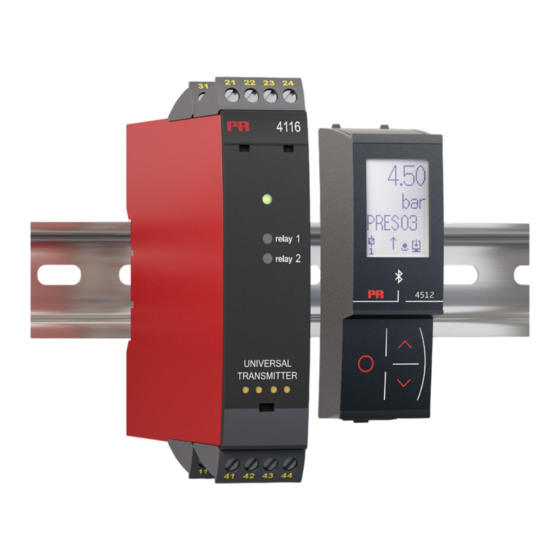
- Page 1 PERFORMANCE MADE SMARTER Product manual 4116 Universal transmitter T E M P E R AT U R E I . S . I N T E R FA C E S CO M M U N I C AT I O N I N T E R FA C E S M U LT I F U N C T I O N A L I S O L AT I O N D I S P L AY...
- Page 2 6 Product Pillars to meet your every need Individually outstanding, unrivalled in combination With our innovative, patented technologies, we make signal conditioning smarter and simpler. Our portfolio is composed of six product areas, where we offer a wide range of analog and digital devices covering over a thousand applications in industrial and factory automation.
-
Page 3: Table Of Contents
Document history ..................4116V106-UK... -
Page 4: Warning
HAZARD- Troubleshooting the device. VOLTAGE Repair of the device and replacement of circuit breakers must be done by PR electronics A/S only. CAUTION Warning To keep the safety distances, the relay contacts on the device must not be connected to both hazardous and non-hazardous voltages at the same time. -
Page 5: Symbol Identification
Should there be any doubt as to the correct handling of the device, please contact your local distributor or, alternatively, PR electronics A/S www.prelectronics.com Mounting and connection of the device should comply with national legislation for mounting of electric materials, i.e. wire cross section, protective fuse, and location. - Page 6 When disconnected, the device may be cleaned with a cloth moistened with distilled water. Liability To the extent the instructions in this manual are not strictly observed, the custom er cannot advance a demand against PR electronics A/S that would otherwise exist according to the concluded sales agreement. 4116V106-UK...
-
Page 7: How To Demount System 4000
This function is not a default option but must be actively selected via the programming menu (S4-20 & S20-4). The error mode can only be reset by switching off and then switching on the supply voltage to the device. 4116V106-UK... -
Page 8: Application
Very low power consumption means units can be mounted side by side without an air gap – even at 60°C ambient temperature. • Configuration, monitoring, 2-point process calibration and more are accomplished using PR's 4500 detachable displays. • All programming can be password-protected. 4116V106-UK... -
Page 9: Applications
Volt - Potentio- meter Current RTD and lin.R Connect., wires Order separately: 5910 CJC connector. See the connection drawing on page 17. Output signals: Relays 10 V 10 V Analog, 0/4...20 mA and voltage Supply: 21.6...253 VAC 19.2...300 VDC 4116V106-UK... -
Page 10: Pr 4500 Display / Programming Front
Demounting of the PR 4500 3: Push the release button on the bottom of the PR 4500 and hinge the the PR 4500 out and up. 4: With the PR 4500 hinged up, remove from holes at the top of the device. 4116V106-UK... -
Page 11: Order
/ V input ........≤ 400 ms Auxiliary supplies 2-wire supply (terminal 44...43) ......25...16 VDC / 0...20 mA 4116V106-UK... - Page 12 Sensor error detection, RTD ......Yes Short circuit detection, RTD ......< 15 Ω 4116V106-UK...
- Page 13 Load (min.) ........500 kΩ of span = of the currently selected measurement range 4116V106-UK...
- Page 14 EU RO Mutual Recognition Type Approval ..... MRA000000Z Functional Safety: Hardware assessed for use in SIL applications FMEDA report - www.prelectronics.com 4116V106-UK...
-
Page 15: Visualisation In The Pr 4500 Of Sensor Error Detection And Input Signal Outside Range
0...10 kΩ SE.BR > ca. 11 kΩ SE.BR > ca. 750 kΩ / (1.25 V) TEMP SE.BR > ca. 15 kΩ RTD, 2-, 3-, and 4-wire No SE.SH for Cuxx, Pt10, Pt20 and Pt50 SE.SH < ca. 15 Ω 4116V106-UK... -
Page 16: Error Indications
All error indications in the display flash once per second. The help text explains the error. If the error is a sensor error, the display backlight flashes as well - this is acknowledged (stopped) by pushing the 3 button. The error is reset by switching off and then switching on the supply voltage to the device. 4116V106-UK... -
Page 17: Connections
41 42 41 42 41 42 41 42 Voltage *TC, CJC connector * Order separately: 41 42 41 42 CJC connector 5910 Outputs: Current Voltage, 1 V Voltage, 10 V Relays 11 12 11 12 11 12 21 22 4116V106-UK... -
Page 18: Block Diagram
A / D D / A 10 V 500 Ω 50 Ω Green 20 Ω EEPROM I + V Out. Out. Out. 50.0 l / min Relay 2 Yellow VALVE 5 Relay 2 Relay 1 4116 Yellow Relay 1 4116V106-UK... -
Page 19: Configuration / Operating The Function Keys
Password protection: Programming access can be blocked by assigning a password. The password is saved in the device in order to ensure a high degree of protection against unauthorized modifications to the configuration. If the configured password is not known, please contact PR electronics support - www.prelectronics.com/contact. Signal and sensor error info via display front PR 4500 Sensor error (see limits in the table) is displayed as SE.BR (sensor break) or SE.SH (sensor short). - Page 20 The following point allows you to activate relay 1 and relay 2 by means of the arrow-keys up/down. You must exit the menu by pressing 3 (no time-out). The simulation function exits automatically, if the PR 4500 is detached. 4116V106-UK...
- Page 21 Please note, however, that when safety readback is enabled, a sensor error will be indicated as an error on the analog output signal. In the CJC menu you can choose between CJC connector and internal cold junction compensation. The CJC connecter (PR 5910) must be ordered separately. 4116V106-UK...
- Page 22 TC.W3 TC.W5 TC.Lr relay will latch again. TC.K SENSOR TC.TYPE Txt 10 Txt 18 Txt 63 Continued on the page Routing diagram ADV.SET 10...100 2W 3W 4W ADV.SET SENSOR Cu TYPE CONNEC. Txt 2 Txt 10 Txt 69 Txt 6 4116V106-UK...
-
Page 23: Routing Diagram
R1.FUNC ERR.ACT Txt 19 Txt 34 R1.FUNC Txt 19 Continued on the next page R1.FUNC Txt 19 Selectable UNITS: mbar mils UNIT in/h l/min Txt 9 in/min mm/s in/s ft/h ft/min m/min ft/s m/s2 gal/h gal/min m3/h m3/min [blank] 4116V106-UK... - Page 24 ERR.ACT ON.DEL OFF.DEL R2.FUNC R2.CONT SETP.LO SETP.HI R2.HYST Txt 31 Txt 32 Txt 33 Txt 19 Txt 27 Txt 29 Txt 28 Txt 30 CLOS OPEN OPEN R2.FUNC ERR.ACT Txt 19 Txt 34 R2.FUNC Txt 19 R2.FUNC Txt 19 4116V106-UK...
- Page 25 Txt 41 Txt 42 HOLD 10-2 CLOS 10-0 OPEN 3600 3600 To default NONE 0000 0000 state 1.0 1-0.2 NONE 2-10 0-10 ERR.ACT ON.DEL OFF.DEL Txt 31 Txt 32 Txt 33 0.2-1 VOLT 0-10 ANA.OUT O.RANGE Txt 36 Txt 39 4116V106-UK...
-
Page 26: Routing Diagram, Advanced Settings (Adv.set)
9999 0000 PASS 0000 SETUP EN.PASS NEW.PAS EN.FAST Txt 43 Txt 54 Txt 55 Txt 56 DE, DK, ES, FR, IT, SE, LANG SETUP LANGUA Txt 43 Txt 59 LATC SETUP R1.LATC R2.LATC Txt 43 Txt 64 Txt 64 4116V106-UK... -
Page 27: Routing Diagram, Manual Deactivation Of The Latch Function
R1 reset 40.0 0000 40.0 To default state 1.0 R1.LATC PASSW R1.LATC R1.RLSE Txt 65 Txt 65 Txt 1 Txt 66 0000 9999 R2 reset 40.0 0000 40.0 R2.LATC PASSW R2.LATC R2.RLSE Txt 65 Txt 65 Txt 1 Txt 66 4116V106-UK... -
Page 28: Help Text Overview
Select 1-5 V output range Select TC-J as sensor type Select TC-K as sensor type Select 0-10 V output range Select TC-L as sensor type Select 2-10 V output range Select TC-N as sensor type Select 1-0.0 V output range 4116V106-UK... - Page 29 Relay 1 is latched - press 1 to release Relay 2 is latched - press 2 to release Relays are latched - press 1 or 2 tor release relay 1 or relay 2 Release relay? (if conditions allow) [66] [67] Enter setup menu? (latched relays may release!) 4116V106-UK...
-
Page 30: Graphic Depiction Of Latch Function Setpoint
ON delay OFF delay Setpoint (increasing) Hysteresis Time Closed Relay latched Relay contact (N.O.) Open Release not possible (setpoint still exceeded) Release not possible (setpoint-hysteresis still exceeded) Release not possible (OFF delay still exceeded) Release possible (manual deactivation) 4116V106-UK... -
Page 31: Graphic Depiction Of Latch Function Window
Graphic depiction of latch function window 4116V106-UK... -
Page 32: Graphic Depiction Of Relay Action Setpoint
Hysteresis = 5 Hysteresis = 5 Relay function: Window (shown for increasing signal) Relay function: Window (shown for decreasing signal) Contact: Closed inside window = Contact: Closed inside window = Contact: Open inside window = Contact: Open inside window = 4116V106-UK... -
Page 33: Document History
Document history The following list provides notes concerning revisions of this document. Rev. ID Date Notes 1948 Relay data updated, graph with resistive loads inserted. EU-RO marine approval added. 2136 UKCA added. 4116V106-UK... - Page 34 We are near you, all over the world Our trusted red boxes are supported wherever you are All our devices are backed by expert service and a 5-year business with a global reach. This means that we are warranty. With each product you purchase, you receive always nearby and know your local markets well.
- Page 35 Benefit today from PERFORMANCE MADE SMARTER PR electronics is the leading technology company specialized in making industrial process control safer, more reliable and more efficient. Since 1974, we have been dedicated to perfecting our core competence of innovating high precision technology with low power consumption.
Need help?
Do you have a question about the 4116V106-UK and is the answer not in the manual?
Questions and answers