Table of Contents
Advertisement
Advertisement
Table of Contents

Related Manuals for PR electronics 4116


Summary of Contents for PR electronics 4116
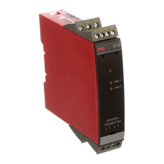
- Page 1 PERFORMANCE MADE SMARTER Product manual 4116 Universal transmitter T E M P E R AT U R E I . S . I N T E R FA C E S CO M M U N I C AT I O N I N T E R FA C E S...
- Page 2 6 Product Pillars to meet your every need Individually outstanding, unrivalled in combination With our innovative, patented technologies, we make signal conditioning smarter and simpler. Our portfolio is composed of six product areas, where we offer a wide range of analog and digital devices covering over a thousand applications in industrial and factory automation.
-
Page 3: Table Of Contents
Universal transmitter 4116 Table of contents Warning .................... -
Page 4: Warning
HAZARD- Troubleshooting the device. VOLTAGE Repair of the device and replacement of circuit breakers must be done by PR electronics A/S only. CAUTION Warning To keep the safety distances, the relay contacts on the device must not be connected to both hazardous and non-hazardous voltages at the same time. -
Page 5: Symbol Identification
Should there be any doubt as to the correct handling of the device, please contact your local distributor or, alternatively, PR electronics A/S www.prelectronics.com Mounting and connection of the device should comply with national legislation for mounting of electric materials, i.e. wire cross section, protective fuse, and location. - Page 6 Normal operation Operators are only allowed to adjust and operate devices that are safely fixed in panels, etc., thus avoiding the danger of personal injury and damage. This means there is no electrical shock hazard, and the device is easily accessible. Cleaning When disconnected, the device may be cleaned with a cloth moistened with distilled water.
-
Page 7: How To Demount System 4000
When front LED lights red / display shows AO.ER PR 4116 is designed as a SIL 2 device with a high safety level. Therefore, a continuous measurement of the outgoing current is carried out on a 4...20 mA and 20...4 mA output signal. If the current output signal is different from the internal calculated output value or the current output is 0 (due to e.g. -
Page 8: Application
When 4116 is used in combination with the 45xx display / programming units, all operational parameters can be modified to suit any application. As the 4116 is designed with electronic hardware switches, it is not necessary to open the device for setting of DIP-switches. -
Page 9: Applications
Applications Input signals: Volt - Potentio- meter Current RTD and lin.R Connect., wires Order separately: 5910 CJC connector. See the connection drawing on page 17. Output signals: Relays 10 V 10 V Analog, 0/4...20 mA and voltage Supply: 21.6...253 VAC 19.2...300 VDC 4116V105-UK... -
Page 10: Pr 45Xx Display / Programming Front
Application • Communications interface for modification of operational parameters in 4116. • Can be moved from one 4116 device to another and download the configuration of the first unit to subsequent units. • Fixed display for readout of process data and status. -
Page 11: Order
Order 4116 = Universal transmitter Accessories 4501 = Display / programming front 4511 = Modbus communication enabler 4512 = Bluetooth communication enabler 5910 = CJC connector Electrical specifications Environmental conditions Operating temperature ....... . -20°C to +60°C Storage temperature . - Page 12 Accuracy, the greater of general and basic values: General values Input type Absolute accuracy Temperature coefficient ≤ ±0.1% of span ≤ ±0.01% of span / °C Basic values Type Basic accuracy Temperature coefficient ≤ ±4 µA ≤ ±0.4 µA / °C ≤...
- Page 13 TC input Min. Max. Type Standard value value 0°C +1820°C IEC 60584-1 -100°C +1000°C IEC 60584-1 -100°C +1200°C IEC 60584-1 -180°C +1372°C IEC 60584-1 DIN 43710 -200°C +900°C -180°C +1300°C IEC 60584-1 -50°C +1760°C IEC 60584-1 -50°C +1760°C IEC 60584-1 -200°C +400°C IEC 60584-1...
- Page 14 Relay outputs Relay functions........Setpoint, Window, Sensor error, Latch, Power and Off Hysteresis .
-
Page 15: Visualisation In The 45Xx Of Sensor Error Detection And Input Signal Outside Range
Sensor error check: Device Configuration Sensor error detection: R1, ERR.ACT=NONE - R2, ERR.ACT=NONE, OUT.ERR=NONE. 4116 Else: Outside range readout (IN.LO, IN.HI): If the valid range of the A/D converter or the polynomial is exceeded Input Range Readout Limit IN.LO... -
Page 16: Error Indications
Error in FLASH 1) No load on the current output Check measurement of analog output current AO.ER (only S4...20 / S20...4 mA) Communications test 45xx / 4116 NO.CO Connection error Check that input signal matches input IN.ER 1) Error levels on input... -
Page 17: Connections
Connections Supply Inputs: TC, internal RTD, 2-wire RTD, 3- / 4-wire Resistance, 2-wire CJC sensor 41 42 41 42 41 42 Resistance, 3- / 4-wire Potentiometer 2-wire transmitter Current 41 42 41 42 41 42 41 42 Voltage *TC, CJC connector * Order separately: 41 42 41 42... -
Page 18: Block Diagram
A / D D / A 10 V 500 Ω 50 Ω Green 20 Ω EEPROM I + V Out. Out. Out. 50.0 l / min Relay 2 Yellow VALVE 5 Relay 2 Relay 1 4116 Yellow Relay 1 4116V105-UK... -
Page 19: Configuration / Operating The Function Keys
In general When configuring the 4116, you will be guided through all parameters and you can choose the settings which fit the application. For each menu there is a scrolling help text which is automatically shown in line 3 on the display. - Page 20 Latch When the setpoint is exceeded the relay outputs enters an alarm state. The latch function of the 4116 will hold the relays in this state until the function is deactivated manually. The latch function can be applied when the relay function setpoint or window is selected.
- Page 21 Password (PASS): Here you can choose a password between 0000 and 9999 in order to protect the unit against unauthorized modifications to the configuration. The unit is delivered default without password. Language (LANG): In the menu ”LANG” you can choose between 7 different language versions of help texts that will appear in the menu.
- Page 22 Power up Fast setpoint adjustment and relay test 50.0 RELAY1 1 Increase setpoint Txt 57 2 Decrease setpoint 3 Save and exit the menu 75.0 1 and 2 simultaneously = change relay state RELAY2 50.0 Txt 57 12.0 2-10 VOLT 0-10 CURR 1111...
-
Page 23: Routing Diagram
Routing diagram If no key is activated for 1 minute, the display will return to the default state 1.0 without saving configuration changes. 1 Increase value / choose next parameter 2 Decrease value / choose previous parameter 3 Save the chosen value and proceed to the next menu Hold 3 Back to previous menu / return to menu 1.0 without saving. - Page 24 SETP WIND HOLD CLOS OPEN 3600 3600 N.O. 100.0 INCR 100.0 NONE 0000 0000 N.C. DECR NONE SETP N.O. 50.0 INCR ERR.ACT ON.DEL OFF.DEL R2.FUNC R2.CONT R2.SETP ACT.DIR R2.HYST Txt 24 Txt 25 Txt 26 Txt 19 Txt 20 Txt 21 Txt 22 Txt 23 HOLD...
- Page 25 S20-4 20-4 20-0 HOLD S4-20 CLOS 23mA 4-20 OPEN 3600 3600 VOLT 0/3.5mA 0-20 NONE 0000 0000 CURR -200 -200 NONE NONE CURR 4-20 23mA 150.0 ERR.ACT ON.DEL OFF.DEL ANA.OUT O.RANGE OUT.ERR OUT.LO OUT.HI Txt 24 Txt 25 Txt 26 Txt 36 Txt 37 Txt 38...
-
Page 26: Routing Diagram, Advanced Settings (Adv.set)
Routing diagram, advanced settings (ADV.SET) DISP PASS 2.0 In the submenu simulation (SIM) you must press 3 SAVE LANG to return to the default state 1.0. LOAD LATC SAVE SETUP MEMORY Txt 43 Txt 44 A.OUT DISP A.OUT SETUP CONTRA LIGHT VALVE 5 LINE 3... -
Page 27: Routing Diagram, Manual Deactivation Of The Latch Function
Routing diagram, manual deactivation of the latch function To setup menu 40.0 Rx.LATC ENT.SET Txt 67 Txt 65 0000 9999 R1 reset 40.0 0000 40.0 To default state 1.0 R1.LATC PASSW R1.LATC R1.RLSE Txt 65 Txt 1 Txt 65 Txt 66 0000 9999 R2 reset... -
Page 28: Help Text Overview
Help text overview [01] Set correct password Select TC-R as sensor type [02] Enter advanced setup menu? Select TC-S as sensor type [03] Select temperature input Select TC-T as sensor type Select TC-U as sensor type Select potentiometer input Select TC-W3 as sensor type Select linear resistance input Select TC-W5 as sensor type Select current input... - Page 29 Enter password setup Enter simulation mode Perform process calibration Enter display setup Perform memory operations Enter relay latch setup [44] Load saved configuration into 4116 Save 4116 configuration in 45xx Adjust LCD contrast [45] [46] Adjust LCD backlight [47] Write a 6-character device TAG...
-
Page 30: Graphic Depiction Of Latch Function Setpoint
Graphic depiction of latch function setpoint Input signal ON delay OFF delay Setpoint (increasing) Hysteresis Time Closed Relay latched Relay contact (N.O.) Open Release not possible (setpoint still exceeded) Release not possible (setpoint-hysteresis still exceeded) Release not possible (OFF delay still exceeded) Release possible (manual deactivation) 4116V105-UK... -
Page 31: Graphic Depiction Of Latch Function Window
Graphic depiction of latch function window 4116V105-UK... -
Page 32: Graphic Depiction Of Relay Action Setpoint
Graphic depiction of relay action setpoint Relay units Relay units Hysteresis = 10 Setpoint = 50 Setpoint = 50 Hysteresis = 10 Off N.O. On N.O. Off N.O. Off N.O. On N.O. Off N.O. On N.C. Off N.C. On N.C. On N.C. -
Page 33: Document History
Document history The following list provides notes concerning revisions of this document. Rev. ID Date Notes 1948 Relay data updated, graph with resistive loads inserted. EU-RO marine approval added. 4116V105-UK... - Page 34 We are near you, all over the world Our trusted red boxes are supported wherever you are All our devices are backed by expert service and a 5-year business with a global reach. This means that we are warranty. With each product you purchase, you receive always nearby and know your local markets well.
- Page 35 Benefit today from PERFORMANCE MADE SMARTER PR electronics is the leading technology company specialized in making industrial process control safer, more reliable and more efficient. Since 1974, we have been dedicated to perfecting our core competence of innovating high precision technology with low power consumption.
Need help?
Do you have a question about the 4116 and is the answer not in the manual?
Questions and answers