Table of Contents
Advertisement
Quick Links
Advertisement
Table of Contents

Subscribe to Our Youtube Channel
Related Manuals for FUTABA FMT-03


Summary of Contents for FUTABA FMT-03
- Page 1 For model 1M23Z04404...
-
Page 2: Table Of Contents
Display ............. 38 System Timer ..........39 User Name ............40 BEFORE USE ........... 11 Sound ............... 41 ●Features of FMT-03 ........11 H/W Setting ............. 42 ●Contents and technical specifications ... 12 Information ............ 44 ●Accessories ............13 Range Check ..........45 ●Transmitter controls ........ - Page 3 TABLE OF CONTENTS Reference Telemetry:GPS [distance] ......78 Telemetry:GPS [speed] ........80 FMT-03 is equipped with a stick of multi-copter exclusive use. Therefore it's unsuitable for use of an Telemetry:GPS [ ] ..81 altitude,variometer,position airplane, a glider and a helicopter.
-
Page 4: Introduction
Phone: 1-256-461-9399 OUTSIDE NORTH AMERICA Please contact your Futaba importer in your region of the world to assist you with any questions, problems or service needs. Please recognize that all information in this manual, and all support availability, is based upon the systems sold in North America only. - Page 5 You may contact your local recycling center for information on where to return the spent battery. Please call 1-800-8BATTERY for information on NiCd battery recycling in your area. Futaba Corporation involvement in this program is part of its commitment to protecting our environment and conserving natural resources.
- Page 6 Charge the batteries! Always recharge the transmitter and receiver batteries before each flying session. A low battery will soon die potentially, causing loss of control and a crash. When you begin your flying session, reset your FMT-03’s built-in timer, and during the session pay attention to the duration of usage.
-
Page 7: Definitions Of Symbols
Use of this product with other than models may be restricted by Export and Trade Control Regulations. 3. Modification, adjustment, and parts replacement Futaba is not responsible for unauthorized modification, adjustment, or replacement of parts on this product. ■ No part of this manual may be reproduced in any form without prior permission. - Page 8 Do not fly at the following places: Before turning on the transmitter: 1. Always move the transmitter throttle stick ■ Near another radio control flying field. position to the minimum (idle) position. ■ Near or above people. 2. Turn on the transmitter first and then the ■...
- Page 9 Charge the battery with the dedicated charger Insert the power cord plug firmly into the supplied with the set. receptacle up to its base. ■ Charging the battery past the specified value may Always use the charger with the specified cause a fire, combustion, rupture, or liquid leakage.
-
Page 10: Storage And Disposal Precautions
Other Precautions CAUTION Do not directly expose plastic parts to fuel, oil, ■ Futaba is not responsible for damage sustained by combination with other than Futaba Genuine Parts. exhaust gas, etc. Use the parts specified in the instruction manual and catalog. -
Page 11: Before Use
Micro SD card (Secure Digital memory card) (Not included) Model data can be saved to a micro SD card (SD:32MB-2GB SDHC:4GB-32GB). When FMT-03 transmitter software files are released, the software can be updated by using a micro SD card update. -
Page 12: Contents And Technical Specifications
Weight: 0.11 oz. (3g) (*1) When using an ESC make sure that it is capable of your applications current draw. Note: The battery in the FMT-03 transmitter is not connected to the battery connector at initial. Please connect the battery connector before use. -
Page 13: Accessories
• Y-harnesses, servo extensions, hub,etc - Genuine Futaba extensions and Y-harnesses, including a heavy- duty version with heavier wire, are available to aid in your larger model and other installations. • Receivers - various models of Futaba receivers may be purchased for use in other models. (Receivers for FASSTest types are available.) -
Page 14: Transmitter Controls
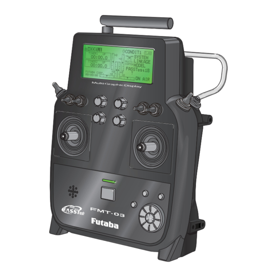
Transmitter controls ●Volume(DA) ●Volume(DB) ●Antenna ●LCD ●Volume(DC) ●Volume(DD) ●Switch SA ●Switch SB ●Stick ●Stick ●U.menu/Mon Button ●Home/Exit Button ●Edit dial ●RTN Button ●Speaker ●Power Switch ●Monitor LED ●S1 Button CAUTION This transmitter is a self neutral stick. A throttle stick of a transmitter for R/ C hobbies of normality is a ratchet-type. -
Page 15: Transmitter's Antenna
Transmitter's Antenna: As with all radio frequency transmissions, the strongest area of signal transmission is from the sides of the transmitter's antenna. As such, the antenna should not be pointed directly at the model. If your flying style creates this situation, easily move the antenna to correct this situation. - Page 16 Attachment and removal of an antenna Install of an antenna FMT-03 can attach or remove an antenna. straight to a screw. Tighten a screw tightly Dust and water aren't supposed to be stuck in an so as not to loosen.
-
Page 17: Switch (Sa-Sh)
Switch (SA-SH) Monitor LED Monitor LED display The status of the transmitter is displayed by LED at the upper part of the front of a FMT-03. RF-ON → Light Blue light • You can choose switch and set the ON/OFF- RF-OFF →... - Page 18 Edit dial operation Data input operation is performed using the edit dial. Edit dial operation Action Reaction • Short 'push' If the screen has more than one page. The cursor moves to the top of next page. If the screen have only one (1) page. The cursor moves to the top of page.
-
Page 19: Home/Exit, U.menu/Mon. Button
Home/Exit and U.menu/Mon. Button Operation of sticks 2 sticks of FMT-03 can do linear operation in left, right, up or down. Home/Exit Button U.menu/Mon Button Home/Exit: Return to the previous Push screen Push and hold Return to the Home screen... -
Page 20: Micro Sd Card
Micro SD card reader/writer included) Saving model data and update files (released from Futaba) into the micro SD card, you can use The FMT-03 transmitter model data those files on your FMT-03 transmitter. Equipment can be stored by using any commonly for reading and writing micro SD cards is available found micro SD card. -
Page 21: Connector
When setting an S.BUS2 servo and telemetry screen in the System menu. sensor, connect them both here. *A transmitter of anything but FMT-03 doesn't correspond to this trainer system. *Do not connect the battery. *An exclusive option trainer code is needed to use a trainer system. -
Page 22: Installation And Removal Of The Battery
Never disconnect the battery connector from the FMT-03 transmitter after turning *Shorting of the battery lead wires may lead to fire and off the power until the screen is completely abnormal heating and cause burns or fire disaster. -
Page 23: Receiver Fmr-03
Receiver FMR-03 ● S.BUS2 Connector LED Monitor ● Be careful about the direction of connector. Direction of connector ● LED Indication Green Status Solid No signal reception Solid Receiving signals Alternate blink Unrecoverable error (EEPROM, etc.) Link/Mode (Typical installation) Switch (It is not used for a link.) S.BUS/S.BUS2 Signal Antenna... -
Page 24: Telemetry Sensor
Telemetry sensor (sold separately) Your aircraft's data can be checked in the transmitter by connecting various telemetry sensors to the hub connector of the receiver. Terminal Futaba Telemetry Sensor Futaba Telemetry Sensor Futaba Telemetry Sensor S.BUS/S.BUS2 Servo Use of multi-copter control box corresponding to S.BUS/S.BUS2 is presupposing for FMR-03. S.BUS/ S.BUS2 servo is connected as shown in the figure. -
Page 25: Receiver's Antenna Installation
Receiver's Antenna Installation The FMR-03 has two antennas. In order to maximize signal reception and promote safe modeling Futaba has adopted a diversity antenna system. This allows the receiver to obtain RF signals on both antennas and fly problem-free. *Must be kept as straight as possible. -
Page 26: Mounting The Servo
Safety precautions when you install Mounting the Servo receiver and servos Wood screw 2.3-2.6mm nut WARNING washer Rubber Rubber grommet grommet Connecting connectors Brass eyelet Brass eyelet Servo mount Be sure to insert the connector until it Servo mount 2.3-2.6mm screw stops at the deepest point. -
Page 27: S.bus2 Devicesetting
S.BUS/S.BUS2 device setting S.BUS/S.BUS2 servos or a telemetry sensor can be connected directly to the FMT-03. Channel setting and other data can be entered for the S.BUS/S.BUS2 servos or sensors. FMT-03 1. Connect the S.BUS/S.BUS2 device you want to set with as shown in the figure. -
Page 28: Basic Operation
The LiFe battery FT2F2100BV2 is only for When the transmitter will not be used for a long time, your FMT-03. Do not use this battery for you should always remove its battery. other equipment. -
Page 29: How To Turn Transmitter Power On/Off
How to turn transmitter power ON/OFF Registration of the user's name When turning on the power, the FMT-03 If so desired, the FMT-03 transmitter can transmitter will begin emmiting RF automatically indicate the owner's name. after it confirms the surrounding RF conditions. -
Page 30: Home Screen
Home screen Use the edit dial to select the following display area to call each setting screen, and Push the RTN button. The setting screen appears. Home Screen Model Name Timer display screen • The model name that • When the cursor is currently used is is moved to the displayed here. -
Page 31: User Menu
WARNING Be sure to confirm the model name before flying your aircraft. Check the battery voltage as often as possible and try to charge the battery earlier. If the battery alarm makes a sound, land your aircraft immediately. *You can adjust the LCD contrast by the display setting in the system menu. User Menu A user menu which allows the user to customize and display frequently used functions has been added. -
Page 32: Key Lock
Auto Lock functions automatically when the model changes or power is turned on. *To temporarily allow access to the FMT-03 programming push and hold the S1 bitton for one second. Please note, the Auto Lock function timer will resume immediately once again. -
Page 33: Link Procedure
Link procedure (FMT-03 ⇔ FMR-03) Each transmitter has an individually assigned, unique ID code. In order to start operation, the receiver must be linked with the ID code of the transmitter with which it is being paired. Once the link is made, the ID code is stored in the receiver and no further linking is necessary unless the receiver is to be used with another transmitter. - Page 34 10. When a telemetry function is enabled, the receiving interval (down-link interval) of sensor data can be changed. If a DL interval is increased, the response of the sensor data display becomes slower, but stick response will improve. Initial value: 1.0s Adjustment range: 0.1s~2.0s * If there are many FASSTest systems turned on around your receiver, it might not link to your transmitter.
-
Page 35: Range Testing Your R/C System
It is extremely important to range check your models prior to each flying session. This enables you to ensure that everything is functioning as it should and to obtain maximum enjoyment from your time flying. The FMT-03 transmitter incorporates a system that reduces its power output and allows you to perform such a range check. -
Page 36: Channels Connection By Multicopter Type
Cannels connection by multicopter type The FMT-03 transmitter channels are automatically assigned for optimal combination according to the type selected with the Model Type function of the Linkage Menu. The channel assignment (initial setting) for each model type is shown below. Connect the receiver and servos to match the type used. -
Page 37: Functions Of System Menu
SYSTEM MENU The System Menu sets up functions of the transmitter: This does not set up any model data. ● Select [SYSTEM] at the home screen and call the system menu shown below by pushing the RTN button. ● Scrolling the edit dial to select the function you want to set and call the setup screen by pushing the RTN button. -
Page 38: Display
RTN button to switch to the data input mode and adjust the contrast by turning the *To temporarily allow access to the FMT-03 programming edit dial to the left and right. push and hold the S1 button for one second. Please note,... -
Page 39: System Timer
● System timer displayed on the home screen can be selected. on the home screen. ● FMT-03 has two type system timers. TOTAL timer: Displays the total accumulated time on the transmitter from the last time the timer was reset. -
Page 40: User Name
USER NAME User name registration This function registers the FMT-03 user name. *A name of up to 12 characters can be entered as the user name. (Space is also counted as 1 character.) ● Select [USER NAME] at the system menu and call the setup screen shown below by pushing the RTN button. -
Page 41: Sound
SOUND Turns off the buzzer. 3 independent sound volumes: "WARNING", "VOICE" and others, are available. "LOW BATTERY" adjusts low battery alarm voltage to match a battery. ● Select [SOUND] at the system menu and access the setup screen shown below by pushing the RTN button. <Edit dial>... -
Page 42: H/W Setting
Note: This will not change the throttle ratchet, etc. Those are mechanical changes that This function reverses the operation signal of the must be done by a Futaba service center. sticks, switches, trimmer levers, and knobs. Note: After changing the mode, it is applied Note: This setting reverses the actual operation when setting a new model. - Page 43 Stick calibration method 5. Set the J3-J4 stick fully to the top-left and *J3-J4 correction is described below. J1-J2 corrections are wait until the buzzer sounds. performed using the same procedure. 1. Select [CALIBRATION] and access the setup screen shown below by pushing the RTN button.
-
Page 44: Information
Home/Exit button. Information Unit system selection "VERSION": FMT-03 system program version 1. Use the edit dial to move the cursor to the information "UNIT SYSTEM" item and push the RTN button to switch to the data input mode. -
Page 45: Range Check
RF operation as noted on the display. while the RF transmission is active. *Once the FMT-03 is transmitting at full power, it is not 2. In the system menu, choose the 'Range possible to enter the Range Check mode without first Check' selection from the menu options. -
Page 46: S.bus Servo
●Servo ID number Individual ID numbers are memorized for your S.BUS servos in your FMT-03. When a servo is used (as shown at the right), the servo ID number is automatically read by the transmitter. - Page 47 S.BUS Servo Description of function of each parameter *There are some functions which can only be used with certain types of servos. • ID Displays the ID of the servo whose parameters are to be read. It cannot be changed. •...
- Page 48 • Boost ON/OFF OFF : The boost turns ON at the time of lower-demand operation. (In most cases) ON : The boost is always ON. (When quick operation is needed) • Damper The characteristic when the servo is stopped can be set. When smaller than the standard value, the characteristic becomes an overshoot characteristic.
-
Page 49: Functions Of Linkage Menu
FUNCTIONS OF LINKAGE MENU The Linkage Menu is made up of functions The functions which can be selected depend on which perform model addition, model type the model type. A typical menu screen is shown selection, frequency setting, end point setting, and below. -
Page 50: Servo Monitor
SERVO MONITOR Servo Test & Graph Display / Displays servo positions. This is used for testing servo movement. In order to prevent any potential difficulties, “Moving Test” (repetition mode) and “Neutral the servo test function will be inoperable, or Test” (fixed position mode) are available. inaccessible, under certain conditions. -
Page 51: Model Select
This function is used to load the settings of the and the model name always appears in the display desired model into the FMT-03’s memory. screen. The Copy function is used to copy one set of model data into a second memory within the The settings may be selected from either the transmitter and the micro SD card. - Page 52 RTN button. 2. Use the edit dial to move to [RENAME]. *FMT-03 accepts a Micro SD card formatted FAT file system, but it does not supports the long file name feature used in 3.
-
Page 53: Model Type (This Function Isn't Used)
1. Use the edit dial to move the cursor to the item you want to change and then call the selection screen by pushing the RTN button. FMT-03 is equipped with a stick of multi-copter "TYPE": Model type exclusive use. Therefore it's unsuitable for use of an airplane, a glider and a helicopter. -
Page 54: System Type
System Type selection Dual receiver function (only FASSTest 18CH mode) The FMT-03 is for 2.4GHz only. The system can be changed from among 2 choices: FASSTest Dual receivers can be linked with the FMT-03. 18CH and FASSTest 12CH which can be chosen by Two receivers are recognized individually by ID FMR-03 set. - Page 55 Telemetry function (FASSTest 18CH mode only) In DUAL, a primary receiver is link previously. Next, a secondary receiver is link. To use the telemetry function, set “Telemetry” to “ACT”. 3. Push the RTN button to end adjustment and return to the cursor mode. DL Interval (FASSTest 18CH mode only) When a telemetry function is enabled, the receiving interval (down-link interval) of sensor...
-
Page 56: Function
FUNCTION Channel assignment of each function can be changed. When you select model and wing (swash) types, Servo Output Channels you will find that the optimized combinations of For FASSTest 12CH mode, you can set 12 linear servo output channels and functions have been channels and two digital channels. - Page 57 Trim setting WARNING Use the edit dial to move the cursor to the As a safety precaution to prevent the motor "TRIM" item of the channel you want to from starting unexpectedly, please switch change and push the RTN button. off the motor accordingly.
-
Page 58: Sub-Trim
SUB-TRIM Setting of neutral position of each servo. The Sub-Trim function is used to set the servo neutral position, and may be used to make fine adjustments to the control surface after linkages and pushrods are hooked up. When you begin to set up a model, be sure that the digital trims are set to their center position. -
Page 59: Servo Reverse
SERVO-REVERSE Use to reverse the throw direction. Servo Reverse changes the direction of an that control multiple servos, it may be confusing individual servo’s response to a control stick to tell whether the servo needs to be reversed or a movement. -
Page 60: Fail Safe
●Remember to set the throttle channel fail safe function so that the servo moves to the maximum slow side for The FMT-03 system also provides you with an airplanes and to the slow side from the hovering position advanced battery monitoring function that warns for helicopters. -
Page 61: End Point
END POINT Sets the travel, limit point, and speed of each servo. The End Point function adjusts the left and right NOTE: The servo speed setting is used to set the servo delay for each channel, from channel l to channel 12. The system servo throws, generates differential throws, and uses the programmed speed (delay) to slow down servo will correct improper linkage settings. -
Page 62: Throttle Cut
THROTTLE CUT Stops the engine safely and easily. (Airplane and helicopter only) Throttle cut provides an easy way to stop the engine, by flipping a switch with the throttle stick at idle. The action is not functional at high throttle to avoid accidental dead sticks. -
Page 63: Idle Down
IDLE DOWN Lowers the engine idling speed. (Airplane and helicopter only) The Idle Down function lowers the engines idle by flipping a switch with the throttle stick at idle. The action is not functional at high throttle to avoid accidental dead sticks. The switch’s location and direction must be chosen, as it defaults to NULL. -
Page 64: Timer
TIMER Timer setting The Timer function may be set for any desired Each timer may be set for count-down or count time, i.e. engine run time, specified times for up operation with a target time. competitions, etc. Two independent timers are If a target time is set and the timer reaches the set provided for your use. - Page 65 Alarm mode *A mode which sounds an alarm every minute during the remaining time up to the timer alarm time. 1 . C h a n g e t h e s e t t i n g b y P u s h i n g ↑ o r ↓...
-
Page 66: T1-T6 Setting
Trim lever T1-T6 isn't This function adjusts the digital trim's control step amount and operation mode (T1-T6). equipped in FMT-03. When the flight conditions are set, the trim operation can be coupled with among all the conditions which combination mode is selected. -
Page 67: Multiprop
MULTIPROP CH is extended by MPDX-1 of an option The system has compatible with the Futaba MPDX-1 multiprop decoder. One channel can be expanded to 8 channels by using the MPDX- 1 multiprop decoder. Up to two MPDX-1 can be used. -
Page 68: Function Name
FUNCTION NAME Function name can be changed T h e n a m e o f t h e s p a r e f u n c t i o n s (AUXILIARY1-8) can be changed for the full name (10 characters) or for the abbreviated name (4 characters).
Need help?
Do you have a question about the FMT-03 and is the answer not in the manual?
Questions and answers