Table of Contents
Advertisement
Quick Links
Advertisement
Table of Contents

Related Manuals for AIC SB303-LB


Summary of Contents for AIC SB303-LB
- Page 1 SB303-LB Storage Server Barebone User's Manual UM_SB303-LB_v3.1_120716...
-
Page 2: Table Of Contents
CONTENTS PREFACE ................... i SAFETY INSTRUCTIONS ..............ii Chapter 1. Prodcut Introduction ..........1 1.1 Box Content ..................1 ..................2 1.3 General Information ................3 Chapter 2. Hardware Installation ..........6 2.1 Central Processing Unit (CPU) ............6 2.2 System Memory ................14 2.3 Removing and Installing Top Cover ..........18 2.4 Installing/ Removing a Hard Disk Drive ..........19 2.5 Removing and Installing a PSU Module .........21 2.6 Removing and Installing a Fan Module .........22... - Page 3 5.1 Method 1 (Use the BIOS setup) ............57 5.2 Method 2 (Use a Dos tool - Syscheck) ...........60 5.3 Connect to BMC ................62 5.4 Web UI ....................63 5.4 Updating BMC Firmware ..............70 Chapter 6. Hardware Introduction ........... 71 6.1 HARDWARE DESIGN SPECIFICATION ..........71 6.2 HARDWARE DESIGN SPECIFICATION ..........73 6.3 Drive Slot Map ...................77 Chapter 7.
- Page 4 Copyright © 2016 AIC, Inc. All Rights Reserved. This document contains proprietary information about AIC products and is not to be disclosed or used except in accordance with applicable agreements.
-
Page 5: Preface
AIC shall not be liable for technical or editorial errors or omissions contained herein. The information provided is provided "as is" without warranty of any kind. To the extent permitted by law, neither AIC or its affiliates, subcontractors or suppliers will be liable for incidental, special or consequential damages including downtime cost;... -
Page 6: Safety Instructions
SAFETY INSTRUCTIONS • Before getting started, please read the following important cautions: • All cautions and warnings on the equipment or in the manuals should be noted. • Most electronic components are sensitive to electrical static discharge. Therefore, be sure to ground yourself at all times when installing the internal components. - Page 7 • product, voltage and current marked on the product’s electrical ratings label. The voltage and current rating of the cord should be greater than the voltage and current rating marked on the product. • If the equipment is not used for a long time, disconnect the equipment from mains to avoid being damaged by transient over-voltage.
-
Page 8: Chapter 1. Prodcut Introduction
• Enclosure( Power supply, fan, 32 x 3.5'' HDD tray included) • 3.5’’ HDD Tray • Power cord • Screws kit x 1pcs • (Include console serial cable) • Slide rail x 1set PACKAGE CONTENT MAY VARY PER REGION. SB303-LB User's Manual... - Page 9 Chapter 1 Product Introduction SB303-LB User's Manual...
-
Page 10: General Information
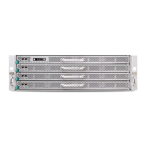
Chapter 1 Product Introduction 1.3 General Information SB303-LB is a 3U rackmount chassis with 32 x 3.5”HDD hot swap Bays at Top and single 12G expander on HDD Backplane which is a high performance server storage product. • Front Panel System power on/off and system reset 4 drawers, each loads 8 x 3.5”... - Page 11 Chapter 1 Product Introduction • Rear Panel 7 x slots 1200W 1+1 redundant 80+ Gold SB303-LB User's Manual...
-
Page 12: Chapter 1 Product Introduction
Chapter 1 Product Introduction • Major Components 1200W 1+1 redundant 80+ Gold AIC Server Board Libra AIC Server Board Libra 3 x 80x38 PWM hot swap fans 3 x 80x38 PWM hot swap fans 4 drawers, each loads 8 x 3.5” drives... -
Page 13: Chapter 2. Hardware Installation
• Proceed to screw 2 and loosen it by giving it two rotations and stop (see letter B). Similarly, loosen screws 3 and 4. Repeat steps A and B by giving each screw two rotations each time until all screws are loosened. • Lift the heatsink straight up (see letter C). SB303-LB User's Manual... -
Page 14: Installing The Processor
2.1.2.1 Unlatch the CPU Load Plate • Push the lever handle labeled “OPEN 1st” (see letter A) down and toward the CPU socket. Rotate the lever handle up. • Repeat the steps for the second lever handle (see letter B). SB303-LB User's Manual... - Page 15 2.1.2.2 Lift open the Load Plate • Rotate the right lever handle down until it releases the Load Plate (see letter A). • While holding down the lever handle, with your other hand, lift open the Load Plate (see letter B). SB303-LB User's Manual...
-
Page 16: Install The Processor
The processor must align correctly with the socket opening before installation. DO NOT DROP the processor into the socket. NOTE : When possible, a CPU insertion tool should be used when installing the CPU. SB303-LB User's Manual... - Page 17 Make sure the load plate tab engages under the socket lever when fully closed. • b.Repeat the steps to latch the locking lever on the other side (see letter C). Latch the levers in the order as shown. SB303-LB User's Manual...
- Page 18 (see letter D). Similarly, engage screws 3 and 4. • Repeat steps C and D by giving each screw two rotations each time until each screw is lightly tightened up to a maximum of 8 inch-lbs torque (see letter E). CAUTION: Do not over-tighten fasteners. SB303-LB User's Manual...
-
Page 19: Removing The Processor
Remove the processor by carefully lifting it out of the socket, taking care NOT to drop the processor and not touching any pins inside the socket. Install the socket cover if a replacement processor is not going to be installed. SB303-LB User's Manual... - Page 20 Caution - Possible thermal damage. Avoid moving the heatsink after it has contacted the top of the CPU. Too much movement could disturb the layer of thermal compound, causing voids, and leading to ineffective heat dissipation and component damage. SB303-LB User's Manual...
-
Page 21: System Memory
Slot 3 Slot 2 Slot 1 JBMC_DP note : Slot 1 / Slot 2 /Slot 3 Available ONLY When JCPU0 processor is installed. Slot 4 / Slot 5 /Slot 6 Available ONLY When JCPU1 processor is installed. SB303-LB User's Manual... - Page 22 JDIMMD1 JDIMMF0 JDIMMD0 JDIMME1 JDIMMC1 JDIMME0 JDIMMC0 JDIMMG0 JDIMMA0 JDIMMG1 JDIMMA1 JDIMMB0 JDIMMH0 JDIMMH1 JDIMMB1 CPU1 CPU0 JDIMM_G0 JDIMM_A0 8 DIMMs JDIMM_H0 JDIMM_B0 CPU0 CPU1 JDIMM_F0 JDIMM_D0 JDIMM_E0 JDIMM_C0 JDIMMF1 JDIMMD1 JDIMMF0 JDIMMD0 JDIMME1 JDIMMC1 JDIMME0 JDIMMC0 SB303-LB User's Manual...
- Page 23 JDIMMA0 CPU1 CPU0 JDIMMG1 JDIMMA1 JDIMMH0 JDIMMB0 JDIMM_G0 JDIMM_A0 JDIMMH1 JDIMMB1 JDIMM_G1 JDIMM_A1 JDIMM_H0 JDIMM_B0 16 DIMMs JDIMM_H1 JDIMM_B1 CPU0 CPU1 JDIMM_F1 JDIMM_D1 JDIMM_F0 JDIMM_D0 JDIMM_E1 JDIMM_C1 JDIMMF1 JDIMMD1 JDIMMF0 JDIMMD0 JDIMM_E0 JDIMM_C0 JDIMME1 JDIMMC1 JDIMME0 JDIMMC0 SB303-LB User's Manual...
- Page 24 2.2.2 DIMM Installation Procedure Unlock a DIMM socket by pressing the retaining clips outward. Insert module vertically and press down until it snaps into place. Note: DIMM notch and socket bump must align as shown. DIMM notch SB303-LB User's Manual...
-
Page 25: Removing And Installing Top Cover
Chapter 2 Hardware Installation 2.3 Removing and Installing Top Cover Loosen 10 screws on top cover. Take it out of the enclosure. SB303-LB User's Manual... -
Page 26: Installing/ Removing A Hard Disk Drive
Slide the tray out of the cage by release the latch. Remove the screw holding the hard drive tray in place. These screws cannot be removed completely from the tray. They are fastened to the tray to avoid loss. Grab the hard drive and pull to remove. SB303-LB User's Manual... - Page 27 Directly place HDD into tool-less HDD tray untli it snaps. Please check if the screw holes on HDD match the dimples on HDD tray. HDD can also be screwed on HDD tray by fastening two screws as picture showed. SB303-LB User's Manual...
-
Page 28: Removing And Installing A Psu Module
2. Pushing the latch and hold the tray handle. 3. Pull the PSU module tray handle out gently to slides out the PSU module. 2.5.2 Installing a PSU Module • To install PSU module, follow the reverse order. SB303-LB User's Manual... -
Page 29: Removing And Installing A Fan Module
Chapter 2 Hardware Installation 2.6 Removing and Installing a Fan Module 2.6.1 Removing a fan module Loosen the screws shown in the diagram below and remove the bar by lifting it upwards. SB303-LB User's Manual... - Page 30 NOTE: The heat sink’s fans should be blowing toward the rear end of the chassis. If one of the fans is facing the wrong direction, please remove the heat sink and reinstall it so that it is facing the correct direction. SB303-LB User's Manual...
- Page 31 Chapter 2 Hardware Installation Pull the fan module up gently and taking out the fan module by removing rubbers out from the fan bar. 2.6.2 Installing a Fan Module inserted. SB303-LB User's Manual...
-
Page 32: Removing And Installing The Hdd Backplane Module
• Grasp and lift up the blackplane then can get out. 2.7.2 Installing a HDD backplane module • Slide the HDD backplane module into enclosures. • Secure the HDD backplane module onto the enclosures using the screws. Follow the reverse order. SB303-LB User's Manual... -
Page 33: Removing And Installing A Pcie Card
• Take the card and check for downside printedbord connectors. keep that connector sitd downward and either side in your hand. chek the below position: 1. Location to external connector side of card. 3. PCI Slot to put card printedboard connectors. SB303-LB User's Manual... - Page 34 Chapter 2 Hardware Installation 4. Location of screws. • Insert the card gently rolling in the side "right" between the edge of the motherboard and the wall of the Storage Server Barbone. • screws in Storage Server Barbone. SB303-LB User's Manual...
- Page 35 Chapter 2 Hardware Installation • Check your earthing is working properly . • Turn on your Storage Server Barbone, system detects new hardware. 5. To remove PCIe Card, follow the reverse order. SB303-LB User's Manual...
- Page 36 Insert the other end of the SFF-8643 to SFF-8643 cable into the corresponding expander borad ports on site of the barebone. Drawer 4 Drawer 4 Drawer 3 Drawer 3 Drawer 2 Drawer 2 Drawer 1 Drawer 1 SB303-LB User's Manual...
- Page 37 Chapter 2 Hardware Installation Each external SAS port can connect JBOD and then each JBOD can connect to another JBOD. SB303-LB User's Manual...
- Page 38 Installation Instructions for two RJ45 module types . • Type 1. Remove PCI Bracket Slot Cover. 2. Take the RJ45 module insert the either one slot onto the chassis. 3. Be sure the RJ45 module insert to chassis properly. SB303-LB User's Manual...
- Page 39 Chapter 2 Hardware Installation • Type module. 2. Align the module to the top and botton of the I/O shield for correct direction. 3. Secure the RJ45 module on the I/O shield using the screws. SB303-LB User's Manual...
- Page 40 Chapter 2 Hardware Installation 2.11.2 Insert one end of the cable into port LAN3 of the barebone. Insert the other end of the cable into the corresponding port LAN4 on site of the barebone. 1. Type 2. Type SB303-LB User's Manual...
-
Page 41: Tool-Less Blade Slide Installation Instruction
Secure the chassis inner with screw form standard screw kit after all the bayonets go through the cut-outs and properly engage. Bayonet on chassis shall be pre-formed as per the recommended dimension and location. SB303-LB User's Manual... - Page 42 Push the safety lock forward to secure the bracket. It is important to check if the safety lock is in unlocked position before mounting the brackets. Release safety lock before mounting Push the safety lock forward to secure SB303-LB User's Manual...
- Page 43 : Very Important- It Requires At Least 2 People To Install The Chassis For Safety Puropose. Retainer Retainer is in fully open position. Press trigger down to release the slides from locking. SB303-LB User's Manual...
-
Page 44: Chapter 3. Motherboard Settings
Chapter 3 Motherboard Setting Chapter 3. Motherboard Settings This section describes the jumpers, internal connectors, and internal LEDs setting on Libra motherboard. Motherboard layout and important jumper settings are listed as below. 3.1 Motherboard block diagram SB303-LB User's Manual... -
Page 45: Motherboard Block Diagram
PCIe slot3 JBAT JSGPIO SATA2 SATA1 JSSGPIO JCMOS JPCH_GPIO SATA4 SATA3 JNTB PCIe slot2 JLPC_DP SATA5 SATA6 I210 I217 JSPKR1 SATA8 SATA7 PCIe slot1 JUSB_INT JNGFF JBMC_RST JBMC_DIS JBMC_DP JFRNT_SSI JLAN2 JLAN1 JLAN2 JCOM4 JLCM JINTRUDERJ BMC_I2C1 SB303-LB User's Manual... -
Page 46: Motherboard Content List
Chapter 3 Motherboard Setting 3.3 Motherboard Content List SB303-LB User's Manual... - Page 47 JDIMMD0 JDIMMC1 JDIMMC0 JPG_LOOK1 JSPI JBUZZER JDOM_PWR JPWR3 JBMC_GPIO JTPM JSGPIO JSSGPIO JCMOS JPCH_GPIO JNTB JLPC_DP JUSB_INT JSPKR1 JNGFF JUSB_INT JFRNT_SSI JBMC_RST JBMC_DIS JBMC_DP JFRNT_SSI JLAN1 JLAN2 JCOM4 JLCM JINTRUDER JBMC_I2C1 JPMBUS PWM4 FAN7_TACH +12V HM_TD7- HM_TD7+ SB303-LB User's Manual...
- Page 48 Chapter 3 Motherboard Setting JPWR3 JDOM_PWR JPG_LOOK1 JUSB_INT SB303-LB User's Manual...
- Page 49 JBAT JSGPIO SATA2 SATA1 JSSGPIO JCMOS JPCH_GPIO SATA4 SATA3 JNTB JLPC_DP SATA6 SATA5 JSPKR1 SATA8 SATA7 JNGFF JUSB_INT JBMC_RST JBMC_DIS JBMC_DP JFRNT_SSI JLAN1 JLAN2 JCOM4 JLCM JINTRUDER JBMC_I2C1 JTPM JSGPIO JSSGPIO JCMOS JNTB JSPKR1 SB303-LB User's Manual JLAN1 JLAN2 JCOM4...
- Page 50 Chapter 3 Motherboard Setting JTPM JSGPIO JSSGPIO +3.3V PCH_SPI_MISO PCH_SPI_MOSI PCH_SPI_CLK PCH_GPIO23 PCH_SPI_CS1_N PCH_LDRQ0_N PCH_SPI_CS2_N RST_PLTRST_N JSPKR1 JLAN2 JLAN1 JLAN4 SB303-LB User's Manual...
- Page 51 JDOM_PWR JPWR3 JBMC_GPIO JTPM JBAT JSGPIO SATA2 SATA1 JSSGPIO JCMOS JPCH_GPIO SATA4 SATA3 JNTB JLPC_DP SATA6 SATA5 JSPKR1 SATA8 SATA7 JNGFF JUSB_INT JBMC_RST JBMC_DIS JBMC_DP JFRNT_SSI JLAN1 JLAN2 JCOM4 JLCM JINTRUDER JBMC_I2C1 JPCH_GPIO JLPC_DP JNGFF JBMC_DP JLCM SB303-LB User's Manual...
- Page 52 Chapter 3 Motherboard Setting JLPC_DP PCH_GPIO21 JPCH_GPIO PCH_GPIO27 JBMC_DP JLCM SB303-LB User's Manual...
- Page 53 Chapter 3 Motherboard Setting SB303-LB User's Manual...
- Page 54 Chapter 3 Motherboard Setting JNGFF SB303-LB User's Manual...
- Page 55 JBMC_I2C10 JBUZZER JPWR3 JDOM_PWR PCIe slot4 LSISA JBMC_GPIO JTPM S3008 PCIe slot3 JSGPIO JSSGPIO JCMOS JPCH_GPIO JNTB PCIe slot2 JLPC_DP I210 I217 JSPKR1 PCIe slot1 JUSB_INT JNGFF JBMC_RST JBMC_DIS JBMC_DP JINTRUDER JFRNT_SSI JLAN1 JLAN2 JCOM4 JLCM JBMC_I2C1 SB303-LB User's Manual...
- Page 56 Chapter 3 Motherboard Setting JPWR1 JVGA_INT JPMBUS +12V DACROA DACGOA +12V DDC_DATAO +12V DACBOA AHSYNCO +12V DVO_5V AVSYNCO DDC_CLKO JBMC_I2C10 JBUZZER JBMC_GPIO BMC BUZZER- I2C10SDA I2C10SCL JBMC_I2C1 SB303-LB User's Manual...
-
Page 57: Leds
Chapter 3 Motherboard Setting 3.5 LEDs 3.5.1 Front Panel LED SB303-LB User's Manual... - Page 58 Chapter 3 Motherboard Setting 3.5.2 Rear Panel LED SB303-LB User's Manual...
- Page 59 Chapter 3 Motherboard Setting 3.5.3 Internal LEDs LED4 LED1 LED3 LED2 SB303-LB User's Manual...
- Page 60 Caution: When Quiet Boot IS enabled, OEM LOGO WILL BE displayed INSTEAD OF POST MESSAGES. Press ESC to run the setup procedure. There will be a message “Entering SETUP” displayed on the diagnostics screen. Caution: For the official released version, the last digit of the BIOS Version must end in an "0."...
- Page 61 Identify the BIOS Version Load Optimal Default setting Save the setting and exit the BIOS setup utility.
-
Page 62: Updating Bios
4.1 Updating BIOS Important Notes: To identify the current BIOS version, please check out on BIOS setup. - Page 63 Update BIOS by INSYDE H2OFFT-D utility under DOS environment If you need to update Flash in the DOS environment, please use Execute to update Flash in the DOS environment. Reboot system.
-
Page 64: Chapter 5
Chapter 5. Insert Ethernet LAN cable into the BMC LAN port. There are two methods to setup BMC IP: BMC management port 5.1 Method 1 (Use the BIOS setup) • BIOS SETUP Server Mgmt BMC network configuration Configuration Address source Static... - Page 65 2. Input IP address. Set static IP.
- Page 66 3. Input subnet mask address.
-
Page 67: Method 2 (Use A Dos Tool - Syscheck)
5.2 Method 2 (Use a Dos tool - Syscheck) 1. Type : sc –lanset 2. Modify IP setting Note: type 1 for selecting static IP mode or type 2 for selecting DHCP mode. 3. Input IP address... - Page 68 4. Input submask address. Below IP address is an example using a default IP setting. User is allowed to change the IP address for realistic use. Note: Type sc.exe –langet command to obtain BMC IP and MAC address.
-
Page 69: Connect To Bmc
5.3 Connect to BMC Note: This feature works with JAVA 6 runtime installed console environment. Below IP address is an example using default IP setting. User is allowed to change the IP address for realistic use. 1. Open the browser then type default BMC IP address: 192.168.22.22 WEB GUI. -
Page 70: Web Ui
5.4 Web UI 5.4.1 Dashboard Device Information Displays the Firmware Revision and Firmware Build Time (Date and Time). Network Information Shows network settings for the device. Click on the link Edit to view the Network Settings Page. Remote Control Not support this function. Remote Console Preview Box It will show the console preview of the remote server using java application. - Page 71 5.4.2 FRU information FRU Device ID its corresponding FRU information will be displayed. Basic Information It displays the FRU device ID and device name for the selected FRU device ID. Chassis Information It displays the following • Board Part Number •...
- Page 72 After modify sensors, please clear all logs via this BMC WEB GUI. Server HealthgEvent LoggClear All Event Logs).
- Page 73 5.4.4 Sensor reading All sensor related information will be displayed here. Double click on a record to loggle(ON/OFF)the live widget for that particular sensor.
- Page 74 5.4.5 Event Log This page displays the list of events incurred by different sensors on this device. Double click on a record to see the details of that entry. You can also sort the list of entries by clicking on any of the column headers. BMC Timezone Check this option to display the event log entries logged with the BMC Timezone value.
- Page 75 5.4.6 Hard Disk Status This page displays all the HDD power on/off status, using the "Power On" and "Power Off" button to control HDD status. ACTIONS Power On Select a HDD to turn it power on. Power off Select a HDD to turn it power off. Icon status Green: This slot inserted HDD and power on.
- Page 76 5.4.7 Remote Control: Environmental setting: Press “ALT+C” for local and remote OS mouse control switching.
-
Page 77: Updating Bmc Firmware
XXXXXZYY]; XXXXX: project name ; Example: A:>cd 301C01 A:\ 301C01>a.bat from the FAE or AIC website. system. Notes: 1. DO NOT USE EMM386 IN DOS ENVIRONMENT WHEN UPDATING FIRMWARE OR YOU WILL GET A FAIL. 2. IN SOME CRITICAL CONDITION, AFTER UPDATING BMC... -
Page 78: Chapter 6. Hardware Introduction
SASHD JPWR JFAIL_IN JFAIL_OUT HDD1 HDD2 HDD3 HDD1 6.1.2 Internal Connectors/Jumpers Led status Header - JLED_IN Description Description HDD1_ACT HDD1_FAIL HDD2_ACT HDD2_FAIL HDD3_ACT HDD3_FAIL HDD4_ACT HDD4_FAIL Led Fail status Header – JFAIL_IN Description FAIL_IN_1 FAIL_IN_2 FAIL_IN_3 FAIL_IN_4 SB303-LB User's Manual... - Page 79 Disable External Access LED input. Close Enable External Access LED input. Open Access LED from HDD Pin P11. Close Access LED from SGPIO. Open Identify behavior according to Host. Close Blinking the Identify LED behavior. Open Disable SGPIO. Close Enable SGPIO. SB303-LB User's Manual...
-
Page 80: Hardware Design Specification
Chapter 6 Hardware Instruction 6.2 HARDWARE DESIGN SPECIFICATION 6.2.1 Placement_Expander Card PCBA Placement JPWR2 JFAN1 SASHD1 SASHD13 SASHD12 Expander Flash SASHD2 JEXP_UART1 JI2C4 SASHD3 JI2C3 JI2C2 SASHD4 JEXP2 SASHD5 SASHD6 SASHD7 Sensor SB303-LB User's Manual... - Page 81 Chapter 6 Hardware Instruction 6.2.2 Internal Connectors/Jumpers Power Connector – JPWR2 Description Description +12V +12V +12V +12V +12V +5VSTBY MCU_PG_1 PS_ON# FAN Connector –JFAN1 Description +12V TACH Console for Expander – JEXP_UART1 Description Description DBG_SIRXD SM_SIRXD DBG_SITXD SM_SITXD SB303-LB User's Manual...
- Page 82 Chapter 6 Hardware Instruction I2C – JI2C2, JI2C3, JI2C4 Description Cascade – JEXP2 Description Description E2E_SCL E2E_SCL E2E_SDA E2E_SDA PEER_MATE_N LB_AB0 LB_BA0 LB_AB1 LB_BA1 SB303-LB User's Manual...
- Page 83 DOWN Link Status LEDs Link down Expander alive, 0.833Hz Expander Blink (LED6) Blue (Blinking) (12 seconds per cycle) E x p a n d e r H e a r t B i t Blue (Blinking) Expander FW running (LED5) SB303-LB User's Manual...
-
Page 84: Drive Slot Map
Chapter 6 Hardware Instruction 6.3 Drive Slot Map FIRST LEVEL HBA Card SENCOND LEVEL HBA Card AND SO ON FIRST LEVEL MegaRaid Card AND SO ON SB303-LB User's Manual... -
Page 85: Chapter 7. Technical Support
Chapter 1 Product Introduction Chapter 1 Product Introduction Chapter 7. Technical Support www.aicipc.com • TAIWAN Tel: +886 3 433 9188 Fax: +886 3 287 1818 Email : sales@aicipc.com.tw • CHINA Tel: +86.21.54961421, +86.21.54961422 Fax: Extension: 608 Email Technical Support: support@aicipc.com •...
Need help?
Do you have a question about the SB303-LB and is the answer not in the manual?
Questions and answers