Table of Contents
Advertisement
Quick Links
Advertisement
Table of Contents

Related Manuals for AIC SB101-SP


Summary of Contents for AIC SB101-SP
- Page 1 SB101-SP Storage Server Barebone User's Manual UM_SB101-SP_v1.3_012020...
-
Page 2: Table Of Contents
Table of Contents Preface ������������������������������������������������������������������������������������������������� i Safety Instructions ������������������������������������������������������������������������������ ii About This Manual ������������������������������������������������������������������������������ iv Chapter 1� Product Features �������������������������������������������������������������� 1 1�1 Box Contents ������������������������������������������������������������������������������������1 1�2 Specifications������������������������������������������������������������������������������������2 1�3 Features ��������������������������������������������������������������������������������������������3 Chapter 2� Hardware Setup ���������������������������������������������������������������� 6 2�1 Central Processing Unit Setup ����������������������������������������������������������6 2.1.1 Processor Installation ..................6 2�2 System Memory Setup �����������������������������������������������������������������������9 2.2.1 DIMM Installation ....................9... - Page 3 4�2 BIOS Menu �������������������������������������������������������������������������������������30 4�3 Main �����������������������������������������������������������������������������������������������31 4.3.1 Main ........................31 4�4 Advanced ����������������������������������������������������������������������������������������32 4.4.1 iSCSI Configuration ..................32 4.4.2 Intel® Virtual RAID on CPU ................33 4.4.3 Trusted Computing ..................33 4.4.4 APCI Settings ....................33 4.4.5 Hardware Health Configuration ..............33 4.4.6 Onboard Device Configuration ................
- Page 4 5.2.3 Dashboard ......................55 5.2.4 Sensor ......................55 5.2.5 System Inventory ..................... 56 5.2.6 FRU Information ....................56 5.2.7 Logs and Reports .................... 57 5.2.8 Settings ......................58 5.2.9 Remote Control ....................60 5.2.10 Power Control ....................65 5.2.11 Chassis Identify Control ................66 5.2.12 Set Front Panel Enables ................
- Page 5 Copyright © 2019 AIC, Inc� All Rights Reserved� This document contains proprietary information about AIC products and is not to be disclosed or used except in accordance with applicable agreements.
- Page 6 Document Release History Release Date Version Update Content January User's Manual release to public. 2019 July Note sign update. 2019 August Slide rail update. 2019 January Specifications update. 2020...
-
Page 7: Preface
Disclaimer AIC shall not be liable for technical or editorial errors or omissions contained herein. The information provided is provided "as is" without warranty of any kind. To the extent permitted by law, neither AIC or its affiliates, subcontractors or suppliers will be liable for incidental, special or consequential damages including downtime cost;... -
Page 8: Safety Instructions
Safety Instructions Before getting started, please read the following important cautions: • All cautions and warnings on the equipment or in the manuals should be noted. • Most electronic components are sensitive to electrical static discharge. Therefore, be sure to ground yourself at all times when installing the internal components. •... - Page 9 • If one of the following situations arise, the equipment should be checked by service personnel: 1. The power cord or plug is damaged. 2. Liquid has penetrated the equipment. 3. The equipment has been exposed to moisture. 4. The equipment does not work well or will not work according to its user manual. 5.
-
Page 10: About This Manual
This document pellucidly presents a brief overview of the product design, device installation, and firmware settings for SB101-SP. For the latest version of this user's manual, please refer to the AIC website: http://www.aicipc.com/tw/productdetail/51036. -
Page 11: Chapter 1� Product Features
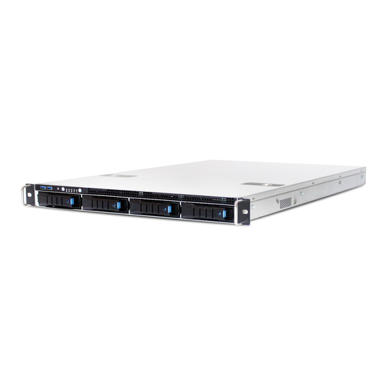
SB101-SP User Manual SB101-SP User Manual Chapter 1. Product Features SB101-SP is a high density storage server that includes mother board, chassis, power supply, and HDD backplane. For more information about our product, please visit our website at http://www.aicipc.com/en. Before removing the subsystem from the shipping carton, visually inspect the physical condition of the shipping carton. -
Page 12: 1�2 Specifications
SB101-SP User Manual Chapter 1. Product Features 1.2 Specifications Riser Card mm : 438 x 680 x 43.5 1 x16 PCIe slot PC1-E16 Dimensions (included) (W x D x H) inches : 17.2 x 26.7 x 1.7 AMI UEFI BIOS... -
Page 13: 1�3 Features
Chapter 1. Product Features 1�3 Features SB101-SP is a reliable 1U storage server barebone with 4 hotswap drives bays. This prod- uct is designed to accommodate the serverboard, Spica, which supports two Intel® Xeon® Scalable Processors and 12 DDR4 DIMM to offer greater perfomance, efficiency, and util- ity for our customers. - Page 14 SB101-SP User Manual Chapter 1. Product Features Front Panel 4x 3.5" HDD tray System button and LED indicator Power On/Off Switch System Power LED System HDD Activity LED LAN LED System Fault LED System ID LED System ID Switch System Reset Switch...
- Page 15 SB101-SP User Manual Chapter 1. Product Features Major Components 450W 1+1 Redundant PSU (optional 500W single PSU, BTO) 6x4028 system fans (optional 6x4056 system fans, BTO)
-
Page 16: Chapter 2� Hardware Setup
Chapter 2� Hardware Setup SB101-SP User Manual Chapter 2. Hardware Setup This section describes a simple instruction guide for installing the hardware components on the serverboard system. NOTE Safety precautions before setup: • Be aware of the placement of the system device. - Page 17 SB101-SP User Manual Chapter 2. Hardware Setup Processor Socket Assembly: The server board includes two processor sockets (LGA-3647), supports one or two of the Intel® Xeon® Processor Scalable Family and has a Thermal Design Power (TDP) of up to 165W on selected models.
- Page 18 SB101-SP User Manual Chapter 2. Hardware Setup PHM Screw Installation Order: The PHM sits level with the processor socket assembly. The PHM is NOT installed properly if it does not sit level with the processor socket assembly. Once the PHM is seated over the processor socket assembly, the four heat sink torque screws must be secured in the following order as shown below.
-
Page 19: 2�2 System Memory Setup
SB101-SP User Manual Chapter 2. Hardware Setup 2�2 System Memory Setup This server board supports 12 DIMM memory slots with 6 channel per CPU. 2�2�1 DIMM Installation Step 1 Unlock the dimm socket by pressing the retaining clips outward. Step 2 Insert the memory module into the slot. Make sure that the DIMM notch is accurately positioned. -
Page 20: Dimm Location
SB101-SP User Manual Chapter 2. Hardware Setup 2�2�2 DIMM Location The DIMMs are displayed on the Spica board as DIMM C0, DIMM B0, DIMM A0, DIMM D0, DIMM E0, DIMM F0, DIMM C1, DIMM B1, DIMM A1, DIMM D1, DIMM E1, and DIMM To ensure satisfactory performance, you need to: ... -
Page 21: Dimm Slot Installation Order
SB101-SP User Manual Chapter 2. Hardware Setup 2�2�3 DIMM Slot Installation Order Populate the DIMM slots according to the suggested order below to ensure a stable system performance. CPU 1 CPU0 DIMM_C1 DIMM_C1 DIMM_C0 DIMM_C0 DIMM_B1 DIMM_B1 DIMM_B0 DIMM_B0 DIMM_A1... -
Page 22: 2�3 Removing The Top Cover
SB101-SP User Manual Chapter 2. Hardware Setup 2�3 Removing the Top Cover Step 1 Press the release button x 2 on the top cover. Step 2 Slide the top cover towards the rear end of the system barebone. Step 3 Lift the cover upward to remove. -
Page 23: 2�4 Removing And Installing The Power Supply Unit Module
SB101-SP User Manual Chapter 2. Hardware Setup 2�4 Removing and Installing the Power Supply Unit Module 2�4�1 Removing the Power Supply Unit Step 1 Press the latch to release the module. Step 2 Pull the handle to remove the module out of the system. -
Page 24: 2�5 Removing And Installing The Fan Module
SB101-SP User Manual Chapter 2. Hardware Setup 2�5 Removing and Installing the Fan Module 2�5�1 Removing the Fan Step 1 Unplug the cables and connectors before dissembling the module. Step 2 Lift the module upward to remove. Check to carefully dislodge the rubber connectors from the attached bracket. -
Page 25: 2�6 Removing And Installing The Hard Disk Drive
SB101-SP User Manual Chapter 2. Hardware Setup 2�6 Removing and Installing the Hard Disk Drive 2�6�1 Removing and Installing the Hard Disk Drive Tray Step 1 Press the release button the tray lever to loosen the lever. Step 2 Pull the tray lever outward completely. -
Page 26: 2�7 Removing And Installing The Hdd Backplane Module
SB101-SP User Manual Chapter 2. Hardware Setup 2�7 Removing and Installing the HDD Backplane Module 2�7�1 Removing the HDD Backplane Step 1 Detach the cables and hard disk drives from the backplane module. Step 2 Release the module by shifting the hook. -
Page 27: 2�8 Removing And Installing The Riser Card
SB101-SP User Manual Chapter 2. Hardware Setup 2�8 Removing and Installing the Riser Card 2�8�1 Removing the Riser Card Step 1 Loosen the captive screw on the riser card braket. Step 2 Pull upward to remove the riser card braket from the system. -
Page 28: 2�9 Slide Rail Installation
SB101-SP User Manual Chapter 2. Hardware Setup 2�9 Slide Rail Installation NOTE This sections provides a basic instruction for mounting the slide rail onto the system. Tool-less rails vary per order. The rail in this manaul may not exactly match the rail for your system. - Page 29 SB101-SP User Manual Chapter 2. Hardware Setup 4. Install the inner rail onto the system barebone. Lock the keyholes and secure the screws on sides of the system. Keyhole screw 5. Continue installing the outer rail bracket to the mounting frame. Attach the outer rail assembling to the frame and press the bracket to form a rack on both ends.
- Page 30 SB101-SP User Manual Chapter 2. Hardware Setup 6. Pull out the middle channel until the ball bearing retainer is locked forward. NOTE Verify ball bearing retainer is locked forward. 7. Slide the release tab and push barebone into rack. Make sure the barebone is completely installed onto the rack.
-
Page 31: Chapter 3� Hardware Settings
Chapter 3� Hardware Settings SB101-SP User Manual Chapter 3. Hardware Settings This section provides illustrations that display the internal jumpers, connectors, and system LED indicators for the system. 3�1 Motherboard Block Diagram... -
Page 32: 3�2 Motherboard Content List
Chapter 3. Hardware Settings SB101-SP User Manual 3�2 Motherboard Content List Connector/Jumper/Header Location Connector/Jumper/Header Location Front Panel VGA System Fan 5 Connector ( not FPIO_VGA2 SYS_FAN_5 Connector available for 1G) ATX 24-pin Power System Fan 4 SYS_FAN_4 Connector Connector NVME RAID Key... -
Page 33: 3�3 Motherboard Layout
SB101-SP User Manual Chapter 3. Hardware Settings 3�3 Motherboard Layout DIMM_C0 DIMM_B0 DIMM_A0 CPU0 DIMM_D0 DIMM_E0 DIMM_F0 DIMM_C1 PCIe_7 (x8) DIMM_B1 DIMM_A1 PCIe_6 (x16) BIOS PCIe_5 (x8) PCIe_4 (x16) CPU1 PCIe_3 (x8) Battery PCIe_2 (x8) DIMM_D1 DIMM_E1 PCIe_1 (x8) DIMM_F1... -
Page 34: 3�4 Connector And Jumper
Chapter 3. Hardware Settings SB101-SP User Manual 3�4 Connector and Jumper 1 FPIO_VGA2: Front Panel VGA Header 5 PW2: 8-pin CPU0 Power Connector 6 PW3: 8-pin CPU1 Power Connector 2 PW1: ATX 24-pin Main Power Connector 11 IPMB_HD1: IPMB Pin Connector... - Page 35 SB101-SP User Manual Chapter 3. Hardware Settings 13 PSMI1: PSMI Connector 18 3PHD4: BMC Console Port5 Jumper (for BMC Debug) Closed Settings 14 FPIO_1: Front Panel Header Pin1-2 BMC COM2 Debug Default Pin2-3 BMC COM5 Debug 19 DBG_HD1: LPC Header...
-
Page 36: 3�5 Hdd Backplane
Chapter 3. Hardware Settings SB101-SP User Manual 3�5 HDD Backplane 3�5�1 Layout Top view Bottom view... -
Page 37: Connector And Jumper Location
SB101-SP User Manual Chapter 3. Hardware Settings 3�5�2 Connector and Jumper Location Top view JPWR2 JPWR1 SASHD JSGPIO_SET CPLD Bottom view HDD1 HDD2 HDD3 HDD4 3�5�3 Connector and Jumper Power Connector: JPWR1 & JPWR2 SGPIO Function and setting Status Description Open Disable External LED input. -
Page 38: Led Indicator
Chapter 3. Hardware Settings SB101-SP User Manual 3�5�4 LED Indicator Blue (On) HDD is present. HDD Activity LED Blue (Blinking) HDD activity is detected or HDD is located. HDD is not connected or the power is off. Off Red (On) HDD fault occurred or HDD is located. -
Page 39: Chapter 4. Bios Configuration Settings
Chapter 4. BIOS Configuration Settings SB101-SP User Manual Chapter 4 BIOS Configuration Settings This chapter demonstrates how to configure the UEFI BIOS settings in your system device. You can enter the BIOS screen during system startup. To enter BIOS configuration settings, •... -
Page 40: 4�2 Bios Menu
Chapter 4 BIOS Configuration Settings SB101-SP User Manual 4�2 BIOS Menu Press and to select the options of the menu bar. Press Enter to access the option screen. Menu Description Displays system information such as CPU bus speed, system memory speed, total installed... -
Page 41: 4�3 Main
SB101-SP User Manual Chapter 4 BIOS Configuration Settings 4�3 Main 4�3�1 Main Main Option Key: Option Key Description System time Configures current time. System date Configures current date. -
Page 42: 4�4 Advanced
Chapter 4 BIOS Configuration Settings SB101-SP User Manual 4�4 Advanced Advanced Option Key: 4.4.1 iSCSI Configuration iSCSI Configuration Add an Attempt Delete Attempts Change Attempt Order... -
Page 43: Intel® Virtual Raid On Cpu
SB101-SP User Manual Chapter 4 BIOS Configuration Settings 4�4�2 Intel® Virtual RAID on CPU Intel® Virtual RAID on CPU All Intel VMD controllers Create RAID Name RAID Level Volume Enable RAID spanned over VMD Controllers Port 0, VMD0, INTEL SSDPE2MD400G4... -
Page 44: Ast2500 Super Io Configuration
Chapter 4 BIOS Configuration Settings SB101-SP User Manual 4.4.7 AST2500 Super IO Configuration AST2500 Super IO Configuration Super IO Chip Read only. Serial Port 1/2 Serial Port Enable Disable Configuration Device Settings Read only IO=3F8h, IRQ=3, 4, 5, Auto IO=3F8h; IRQ=4;... -
Page 45: Option Rom Dispatch Policy
SB101-SP User Manual Chapter 4 BIOS Configuration Settings Legacy OS Redirection 80x24 80x25 Resolution Console VT100 LINUX XTERMR6 Redirection Putty KeyPad Settings ESCN VT400 Redirection after Always Enable BootLoader BIOS POST Legacy Console COM1 COM2 Redirection Settings Out-of-Band COM1 Mgmt Port... -
Page 46: Network Stack Configuration
Chapter 4 BIOS Configuration Settings SB101-SP User Manual 4.4.12 Network Stack Configuration Network Stack Configuration Enable Ipv4 PXE Enable Disable Support Ipv4 HTTP Enable Disable Support Ipv6 PXE Enable Network Stack Disable Disable Support Ipv6 HTTP Enable Disable Support PXE boot wait... -
Page 47: Nvdimm Adr Configuration
SB101-SP User Manual Chapter 4 BIOS Configuration Settings 4.4.15 NVDIMM ADR Configuration NVDIMM ADR Configuration Assert ADR on Reset Enable Disable Assert ADR on Enable Disable Shutdown... -
Page 48: Platform Configuration
Chapter 4 BIOS Configuration Settings SB101-SP User Manual 4.5 Platform Configuration 4.5.1 Platform Configuration Platform Option Key: Option Key Description PCH Configuration Displays and provides option to change the PCH Settings. Miscellaneous Configuration Configures active video type. Server ME Configuration... -
Page 49: Pch Configuration
SB101-SP User Manual Chapter 4 BIOS Configuration Settings 4.5.2 PCH Configuration PCH Configuration PCI Express Root (To Enable Disable AST2500) Disable ASPM PCIE ASPM ASPM L1 ASPM Auto Disable L1.1 L1 Substates PCI Express PCI Express Root Port L1.2 Configuration L1.1 &... -
Page 50: Miscellaneous Configuration
Chapter 4 BIOS Configuration Settings SB101-SP User Manual Enable/Disable ADR Enable Disable ADR GPIO GPIO_B GPIO_C Host Partition Reset ADR Enable Disable Enable Enable/Disable ADR Timer Enable Held-off PCH DFX 25 uS 50 uS ADR timer expire time Configuration 100 uS... -
Page 51: Socket Configuration
SB101-SP User Manual Chapter 4 BIOS Configuration Settings 4.6 Socket Configuration 4.6.1 Socket Configuration Socket Configuration Option Key: Option Key Description Processor Configuration Displays and provides option to change the Processor Settings. Common RefCode Displays and provides option to change the Common RefCode Configuration Settings. -
Page 52: Processor Configuration
Chapter 4 BIOS Configuration Settings SB101-SP User Manual 4.6.2 Processor Configuration Processor Configuration Hyper-Threading [ALL] Enable Disable Max CPUID Value Limit Enable Disable Execute Disable Bit Enable Disable Enable Intel® TXT Enable Disable Enable Disable Enable SMX Enable Disable Lock Chipset... -
Page 53: Memory Configuration
SB101-SP User Manual Chapter 4 BIOS Configuration Settings 4.6.5 Memory Configuration Memory Configuration Enforce POR Auto Disable Memory Frequency Auto 1866 2133 2400 2666 Memory Topology Read only. Mirror Mode Disable Mirror Mode 1LM Mirror Mode 2LM Mirror TAD0 SDDC Plus One... - Page 54 Chapter 4 BIOS Configuration Settings SB101-SP User Manual Auto PCI-E ASPM Support L1 Only Disable Socket 0 Configuration Link Speed Enable L0s Support Disable x4x4x4x4 x8x8 IOU0 (IIO PCIe Br1) Auto x4x4x4x4 x8x8 IOU1 (IIO PCIe Br2) Auto x4x4x4x4 x8x8...
-
Page 55: Advanced Management Power Configuration
SB101-SP User Manual Chapter 4 BIOS Configuration Settings 4.6.7 Advanced Management Power Configuration Advanced Management Power Configuration SpeedStep (Pstates) Enable Disable Max Performance Boot performance Max Efficient mode Set by Intel Node Manager CPU P State Control Energy Efficient Turbo... -
Page 56: 4�7 Server Management
Chapter 4 BIOS Configuration Settings SB101-SP User Manual 4�7 Server Management 4�7�1 Server Management Server Management Option Key: Server Management FRB-2 Timer Enable Disable FRB-2 Timer timeout 3 minutes 4 minutes 5 minutes 6 minutes FRB-2 Timer Policy Do Nothing... -
Page 57: System Event Log
SB101-SP User Manual Chapter 4 BIOS Configuration Settings 4�7�2 System Event Log System Event Log Enable Disable Yes, on next Erase SEL reset Yes, on every reset Do Nothing SEL Components When SEL is Full Erase Immediately Disable Log EFI Status... -
Page 58: 4�8 Security
Chapter 4 BIOS Configuration Settings SB101-SP User Manual 4�8 Security 4�8�1 Security Security Option Key: Security Set administrator password in the Create New Password window. After Administrator you key in the password, the Confirm New Password window will pop out Password to ask for confirmation. - Page 59 SB101-SP User Manual Chapter 4 BIOS Configuration Settings Secure Boot Attempt Secure Boot Enable Disable Secure Boot Mode Standard Custom Provision Factory Default keys Install Factory Default Keys Enroll Efi Image Save All Secure Boot Variables Key Management Platform Key (PK)
-
Page 60: 4�9 Boot
Chapter 4 BIOS Configuration Settings SB101-SP User Manual 4�9 Boot 4�9�1 Boot Boot Option Key: Boot Number of seconds to wait for setup activation key. 65535 (0xFFFF) Setup Prompt Timeout means indefinite waiting. Bootup NumLock State On Quiet Boot Enable... -
Page 61: 4�10 Save And Exit
SB101-SP User Manual Chapter 4 BIOS Configuration Settings 4�10 Save and Exit 4�10�1 Save and Exit Save and Exit Option Key: Save and Exit Save Changes and Exit Exit system setup after saving the changes. Discard Changes and Exit system setup without saving any changes. -
Page 62: Chapter 5. Bmc Configuration Settings
Chapter 5. BMC Configuration Settings SB101-SP User Manual Chapter 5. BMC Configuration Settings 5�1 Login NOTE This feature works with the JAVA 6 run time installed console environment. The IP address below is an example using the default IP setting. The IP address is configurable. -
Page 63: 5�2 Web Gui
SB101-SP User Manual Chapter 5. BMC Configuration Settings 5�2 Web GUI 5�2�1 Menu Bar Click to select the options of the menu bar. Menu Description The Dashboard page gives the overall information about the status of Dashboard a device. Sensor The Sensor Readings page displays all the sensor related information. -
Page 64: User Information And Quick Button
SB101-SP User Manual Chapter 5. BMC Configuration Settings 5�2�2 User Information and Quick Button The user information and quick access buttons are located at the top right corner. It displays the logged-in user, his/her privilege and the four quick buttons allowing you to perform different functions. - Page 65 SB101-SP User Manual Chapter 5. BMC Configuration Settings 5�2�3 Dashboard The Dashboord page displays device, system, and network information. Click Dashboard on the menu bar to view the overall information of the server. 5�2�4 Sensor The Sensor page displays the status and records on related sensors.
-
Page 66: System Inventory
SB101-SP User Manual Chapter 5. BMC Configuration Settings 5�2�5 System Inventory The System Inventory page displays network information, including Vendor name, Model, and Sofware version. Click System Inventory on the menu bar to open. 5�2�6 FRU Information The FRU Information page displays Basic Information, Chassis Information, Board Information and Product Information of the FRU device. -
Page 67: Logs And Reports
SB101-SP User Manual Chapter 5. BMC Configuration Settings 5�2�7 Logs and Reports The System Inventory page displays IPMI Event Log and Video Log. Click Logs and Reports from the menu bar select Event Log or Video Log to view the contents. -
Page 68: Settings
SB101-SP User Manual Chapter 5. BMC Configuration Settings 5�2�8 Settings The Settings page displays the configuration settings for Date & Time, External User Services, KVM Mouse Setting, Log Settings, Media Redirection Settings, Network Settings, PAM Order Settings, Platform Event Filter, Services, SMTP Settings, SSL... - Page 69 SB101-SP User Manual Chapter 5. BMC Configuration Settings Settings Menu and Option Keys: Settings Date and Time LDAP/E-directory Active directory Radius Settings Settings Settings External User Services General Advanced General Role General Role Radius Radius Settings Groups Settings Groups Settings...
-
Page 70: Remote Control
SB101-SP User Manual Chapter 5. BMC Configuration Settings 5�2�9 Remote Control The Remote Control page displays the configuration for power control and remote KVM. Click Java Console to start the JViewer video redirection. - Page 71 SB101-SP User Manual Chapter 5. BMC Configuration Settings Click Launch KVM to open the Remote KVM page.
- Page 72 SB101-SP User Manual Chapter 5. BMC Configuration Settings Procedure To Start KVM Step 1 Click Start KVM to start the H5Viewer video redirection. Step 2 Click Browse to select CD Image. Step 3 Click Start Media to redirect the selected CD image file to the Host.
- Page 73 SB101-SP User Manual Chapter 5. BMC Configuration Settings Remote KVM Menu and Option Key Button Description Start KVM Starts the H5Viewer video redirection. Stop KVM Stops the H5Viewer video redirection. Pause Video This option is used for pausing Console Redirection.
- Page 74 SB101-SP User Manual Chapter 5. BMC Configuration Settings This menu item can be used to act as the right- Right <Ctrl> side <CTRL> key when in Console Redirection. This menu item can be used to act as the right- Right <Alt>...
-
Page 75: Power Control
SB101-SP User Manual Chapter 5. BMC Configuration Settings 5�2�10 Power Control The Power Control page allows you to view and control the power of your server. To open Power Control, click Power Control from the menu bar. The various options of Power Control are given below. -
Page 76: Chassis Identify Control
SB101-SP User Manual Chapter 5. BMC Configuration Settings 5�2�11 Chassis Identify Control The Chassis Identify Control page displays the BMC’s UID control information. Users can change the Identify LED behavior on this page. Click Chassis Identify Control from the menu bar. Select Off/On to control UID LED. - Page 77 SB101-SP User Manual Chapter 5. BMC Configuration Settings 5�2�13 Maintenance This Maintenance page displays the configuration settings for Backup Configuration, Firmware Image Location, Firmware Information, BIOS Information, Fimware Update, Preserve Configuration, Restore Configuration, Restore Configuration, and Restore Factory Defaults.
- Page 78 SB101-SP User Manual Chapter 5. BMC Configuration Settings Maintenance Procedure 1. Click Check All to backup the selected configuration items. The Backup Configuration page will appear Click Download Config to save the backup file to the client system Backup Configuration 2.
-
Page 79: Sign Out
SB101-SP User Manual Chapter 5. BMC Configuration Settings 5�2�14 Sign out To log out of the BMC: Method 1: Click Sign out from the menu bar. The Logout dialog box will pop out. Method 2: Click the root quick button on the top right corner of the screen. -
Page 80: Chapter 6� Technical Support
Chapter 6� Technical Support Taiwain, Global Headquarters South California, United States Address: 21808 Garcia Lane Address: No� 152, Section 4, City of Industry, CA 91789, Linghang N� Rd, Dayuan District, United States Taoyuan City 337, Taiwan Tel: +886-3-433-9188 Toll free: +7-4997019998 Fax: +886-3-287-1818 Tel: +1-909-895-8989 Sales Email: sales@aicipc�com�tw...
Need help?
Do you have a question about the SB101-SP and is the answer not in the manual?
Questions and answers