Table of Contents
Advertisement
Quick Links
Advertisement
Table of Contents

Related Manuals for AIC SB101-UR


Summary of Contents for AIC SB101-UR
- Page 1 SB101-UR Storage Server Barebone User's Manual UM_SB101-UR_v1_010719...
-
Page 2: Table Of Contents
Table of Contents Preface ������������������������������������������������������������������������������������������������ i Safety Instructions ������������������������������������������������������������������������������ ii About This Manual ����������������������������������������������������������������������������� iv Chapter 1� Product Features �������������������������������������������������������������� 1 1�1 Box Contents ������������������������������������������������������������������������������������ 1 1�2 Specifications ����������������������������������������������������������������������������������� 2 1�3 Features �������������������������������������������������������������������������������������������� 3 Chapter 2� Hardware Setup ���������������������������������������������������������������� 6 2�1 Central Processing Unit Setup ����������������������������������������������������������... - Page 3 2�10 Tool-less Slide Blade Installation ��������������������������������������������������� 18 Chapter 3� Hardware Settings ���������������������������������������������������������� 23 3�1 Motherboard Layout ������������������������������������������������������������������������ 23 3�2 Content List ������������������������������������������������������������������������������������� 24 3�3 Motherboard Connector ������������������������������������������������������������������ 25 3�4 HDD Backplane �������������������������������������������������������������������������������� 37 3.4.1 Layout ......................... 37 3.4.2 Connector and Jumper Location ..............38 3.4.3 Connector and Jumper ..................38 3.4.4 LED Indicator .....................
- Page 4 4.6.2 Common RefCode Configuration ..............48 4.6.3 UPI Configuration ....................49 4.6.4 Common RefCode Configuration ..............49 4.6.5 Memory Configuratiuon ..................49 4.6.6 Memory Map ...................... 49 4.6.7 Memory RAS Configuration ................49 4�7 BMC ������������������������������������������������������������������������������������������������ 50 4.7.1 FB-2 Timer ......................50 4.7.2 FB-2 Timer Policy ....................50 4.7.3 BMC Network Configuration ................50 4�8 Security �������������������������������������������������������������������������������������������...
- Page 5 Copyright © 2019 AIC, Inc� All Rights Reserved� This document contains proprietary information about AIC products and is not to be disclosed or used except in accordance with applicable agreements.
- Page 6 Document Release History SB101-UR User Manual Chapter 1. Product Features Release Date Version Update Content January User's Manual release to public. 2019...
-
Page 7: Preface
Disclaimer AIC shall not be liable for technical or editorial errors or omissions contained herein. The information provided is provided "as is" without warranty of any kind. To the extent permitted by law, neither AIC or its affiliates, subcontractors or suppliers will be liable for incidental, special or consequential damages including downtime cost;... -
Page 8: Safety Instructions
Safety Instructions Before getting started, please read the following important cautions: • All cautions and warnings on the equipment or in the manuals should be noted. • Most electronic components are sensitive to electrical static discharge. Therefore, be sure to ground yourself at all times when installing the internal components. •... - Page 9 • If the equipment is not used for a long time, disconnect the equipment from mains to avoid being damaged by transient over-voltage. • Never open the equipment. For safety reasons, only qualified service personnel should open the equipment. • If one of the following situations arise, the equipment should be checked by service personnel: 1.
-
Page 10: About This Manual
This document pellucidly presents a brief overview of the product design, device installation, and firmware settings for SB101-UR. For the latest version of this user's manual, please refer to the AIC website: http://www.aicipc.com/tw/productdetail/51044. -
Page 11: Chapter 1� Product Features
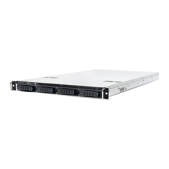
SB101-UR User Manual SB101-UR User Manual Chapter 1. Product Features SB101-UR is a high density storage server that includes mother board, chassis, power supply, and HDD backplane. For more information about our product, please visit our website at http://www.aicipc.com/en. Before removing the subsystem from the shipping carton, visually inspect the physical condition of the shipping carton. -
Page 12: 1�2 Specifications
SB101-UR User Manual Chapter 1. Product Features 1.2 Specifications mm : 438 x 800 x 43.5 • 2 x 10GbE SFP+ Dimensions • 1 x GbE RJ45 dedicated to (W x D x H) inches : 17.2 x 31.5 x 1.7... -
Page 13: 1�3 Features
Chapter 1. Product Features 1�3 Features SB101-UR is a reliable 1U storage server barebone with 4 hotswap drives bays. This product is designed to accommodate the AIC-patented serverboard, Ursa, which supports two Intel® Xeon® Scalable Processors and 24 DDR4 DIMM to offer greater perfomance, efficiency, and utility for our customers. - Page 14 SB101-UR User Manual Chapter 1. Product Features Front Panel 4x 3.5" HDD tray System button and LED indicator System Reset Switch System UID Switch System UID LED System Fault LED System Power LED System Power Switch Rear Panel 2 x SFP+ port...
- Page 15 SB101-UR User Manual Chapter 1. Product Features Major Components...
-
Page 16: Chapter 2� Hardware Setup
Chapter 2� Hardware Setup SB101-UR User Manual Chapter 2. Hardware Setup This section describes a simple instruction guide for installing the hardware components on the serverboard system. Turn off and unplug all system and peripheral devices before proceeding. 2�1 Central Processing Unit Setup The serverboard supports dual Xeon scalable processors and Socket P0 (LGA-3647). -
Page 17: Heatsink
SB101-UR User Manual Chapter 2. Hardware Setup 2�1�2 Heatsink To ensure a safe and easy setup, you need to prepare before installation: 2 heatsinks that support the motherboard. Procedure: Installation Step 1 Position the heatsink on top of the CPU. -
Page 18: 2�2 System Memory Setup
SB101-UR User Manual Chapter 2. Hardware Setup 2�2 System Memory Setup 2�2�1 DIMM Installation Step 1 Unlock the DIMM socket by pressing the retaining clips outward. Step 2 Insert the memory module into the slot. Make sure that the DIMM notch is accurately positioned. -
Page 19: Dimm Location
SB101-UR User Manual Chapter 2. Hardware Setup 2�2�2 DIMM Location To ensure satisfactory performance, you need to: Verify the DIMM type: DDR4 RDIMM/LRDIMM/NVDIMM-N with EEC(Error Correction Code). Verify if all of the DIMMs installed are of the same DIMM type to avoid memory failure and loss of performance speed. -
Page 20: Dimm Slot Installation Order
SB101-UR User Manual Chapter 2. Hardware Setup 2�2�3 DIMM Slot Installation Order Populate the DIMM slots according to the suggested order below to ensure a stable system performance. DIMM CPUs Slots (Connectors) CPU0 CPU1 Slots A0 A1 B0 B1 C0 C1 D0 D1 E0 E1 F0 F1 A0 A1 B0 B1 C0 C1 D0 D1 E0 E1 F0 F1... -
Page 21: 2�3 Removing And Installing The Top Cover
SB101-UR User Manual Chapter 2. Hardware Setup 2�3 Removing and Installing the Top Cover Step 1 Press the release button x 2 on the top cover. Step 2 Remove the top cover. -
Page 22: 2�4 Removing And Installing The Power Supply Unit Module
SB101-UR User Manual Chapter 2. Hardware Setup 2�4 Removing and Installing the Power Supply Unit Module 2�4�1 Removing the Power Supply Unit Step 1 Press the latch and hold the tray on the module. Step 2 Pull the module out of the system barebone. -
Page 23: 2�5 Removing And Installing The Fan Module
SB101-UR User Manual Chapter 2. Hardware Setup 2�5 Removing and Installing the Fan Module 2�5�1 Removing the Fan Step 1 Remove the fan connector from the motherboard by pulling the connector outward and them upward.. Step 2 Pull the fan from the fan slot. -
Page 24: 2�6 Removing And Installing The Hard Disk Drive
SB101-UR User Manual Chapter 2. Hardware Setup 2�6 Removing and Installing the Hard Disk Drive 2�6�1 Removing and Installing the Hard Disk Drive Tray Step 1 Press the release button the tray lever. The lever will be ejected from the tray. -
Page 25: 2�7 Removing And Installing The Hdd Backplane Module
SB101-UR User Manual Chapter 2. Hardware Setup 2�7 Removing and Installing the HDD Backplane Module 2�7�1 Removing the HDD Backplane Step 1 Detach the cables & HDDs from the system. Step 2 Adjust the hook on the side of the backplane to detach it from the system. -
Page 26: 2�8 Removing And Installing The Riser Card
SB101-UR User Manual Chapter 2. Hardware Setup 2�8 Removing and Installing the Riser Card 2�8�1 Removing the Riser Card Step 1 Loosen the captive screw. Step 2 Remove the riser card from the system. 2�8�2 Installing the Riser Card Step 1 Align and insert the riser card with bracket into the riser card slot. Check if the card is properly aligned. -
Page 27: 2�9 Removing And Installing The Airduck
SB101-UR User Manual Chapter 2. Hardware Setup 2�9 Removing and Installing the Airduck Locate the positon of airduck as demonstrated below. Make sure to position it on top of the fan modules. -
Page 28: 2�10 Tool-Less Slide Blade Installation
SB101-UR User Manual Chapter 2. Hardware Setup 2�10 Tool-less Slide Blade Installation 1. Release and detach the inner rail from the slide. PUSH... - Page 29 SB101-UR User Manual Chapter 2. Hardware Setup 2. Attach the inner rail to the barebone. Click!
- Page 30 SB101-UR User Manual Chapter 2. Hardware Setup 3. Attach the outer rail to the rack. Click! Click! PUSH...
- Page 31 SB101-UR User Manual Chapter 2. Hardware Setup 4. Pull out the middle channel until the ball bearing retainer is locked forward. CAUTION Verify ball bearing retainer is locked forward.
- Page 32 SB101-UR User Manual Chapter 2. Hardware Setup 5. Slide the release tab and push barebone into rack. Make sure the barebone is completely installed onto the rack. NOTE Tool-less rails vary per order. The rail in this manaul may not exactly match the rail for...
-
Page 33: Chapter 3� Hardware Settings
Chapter 3� Hardware Settings SB101-UR User Manual Chapter 3. Hardware Settings This section describes the jumpers, internal connectors, and internal LEDs settings in SB101-UR. 3�1 Motherboard Layout CPU1 CPU0... -
Page 34: 3�2 Content List
Chapter 3. Hardware Settings SB101-UR User Manual 3�2 Content List Connector/Jumper/Header Location Connector/Jumper/Header Location SATA/SATADOM VGA Connector J2003 Connector (sSATA 5) Internal Serial Header J2043 Processor 1 CPU1 DIMM Slots for J14, J13, J16, J15, Management Port J2002 Processor 1... -
Page 35: 3�3 Motherboard Connector
SB101-UR User Manual Chapter 3. Hardware Settings 3�3 Motherboard Connector CPU1 CPU0 19 Power Supply Connectors: J84 23 Power Supply Connectors: J85 Description Description Description Description A1 Ground Ground A1 Ground Ground A2 Ground Ground A2 Ground Ground A3 Ground... - Page 36 Chapter 3. Hardware Settings SB101-UR User Manual CPU1 CPU0 24 21 22 42 GPU Power Connectors (J64, J65, J66, J67) Description Description Ground +12V Ground +12V Ground +12V Ground +12V 25 Backplane Power Connector (J95) Description Description Ground +12V Ground...
- Page 37 SB101-UR User Manual Chapter 3. Hardware Settings CPU1 CPU0 45 Front Panel USB Connector (J71) Pin Description Pin Description +5V_USB3_FRONT1 PCH_USB3_RX_P4_ PSV_USB3_FRONT2 ESD_DN PCH_USB3_RX_P4_ PCH_USB3_RX_P5_ ESD_DP ESD_DN Ground PCH_USB3_RX_P5_ ESD_DP PCH_USB3_TX_P4_ Ground ESD_DN PCH_USB3_TX_P4_ PCH_USB3_TX_P5_ ESD_DP ESD_DN Ground PCH_USB3_TX_P5_ ESD_DP...
- Page 38 Chapter 3. Hardware Settings SB101-UR User Manual CPU1 CPU0 43 TPM Connector (J60) Pin Description Pin Description LPC_TPM_Module_AD<0> TPM_Vendor_ID1 TPM_PRSNT_N LPC_AD_1 LPC_FRAME_TPM_Module_N LPC_SERIRQ Ground +3V3 Clock_33M_PCH_LPC_TPM5% 10 RST_LPC_TPM_Module_N 11 Ground 12 LPC_TPM_Module_AD<2> 13 +3V3_STBY 14 Ground 15 Ground 16 LPC_TPM_Module_AD<3>...
- Page 39 SB101-UR User Manual Chapter 3. Hardware Settings CPU1 CPU0 17 Slimline Connector 0 (J48) Pin Description Pin Description A1 Ground B1 Ground A2 PCH_SATA_RX_P0_C_DP B2 PCH_SATA_TX_P0_C_DP A3 PCH_SATA_RX_P0_C_DN B3 PCH_SATA_TX_P0_C_DN A4 Ground B4 Ground A5 PCH_SATA_RX_P1_C_DP B5 PCH_SATA_TX_P1_C_DP A6 PCH_SATA_RX_P1_C_DN...
- Page 40 Chapter 3. Hardware Settings SB101-UR User Manual 18 Slimline Connector 1 (J50) Pin Description Pin Description A1 Ground B1 Ground A2 PCH_SATA_RX_P4_C_DP B2 PCH_SATA_TX_P4_C_DP A3 PCH_SATA_RX_P4_C_DN B3 PCH_SATA_TX_P4_C_DN A4 Ground B4 Ground A5 PCH_SATA_RX_P5_C_DP B5 PCH_SATA_TX_P5_C_DP A6 PCH_SATA_RX_P5_C_DN B6 PCH_SATA_TX_P5_C_DN...
- Page 41 SB101-UR User Manual Chapter 3. Hardware Settings CPU1 CPU0 27 SATA/SATADOM Connectors(sSATA 5) (J52) Pin Description Pin Description Ground PCH_SATA_RX_S5_C_DN PCH_SATA_TX_S5_C_DP PCH_SATA_RX_S5_C_DP PCH_SATA_TX_S5_C_DN +5V_SATADOM_2 Ground Ground 49 SATA/SATADOM Connectors(sSATA 4) (J74) Pin Description Pin Description Ground PCH_SATA_RX_S4_C_DN PCH_SATA_TX_S4_C_DP PCH_SATA_RX_S4_C_DP PCH_SATA_TX_S4_C_DN...
- Page 42 Chapter 3. Hardware Settings SB101-UR User Manual CPU1 CPU0 39 Fan Connectors 1 (J98) Pin Description Pin Description Ground BMC_FAN_PWM_1_R PU_FAN_ID_1 PU_FAN_INSTALL_1_N BMC_FAIL_1_R +12V 38 Fan Connectors 2 (J99) Pin Description Pin Description Ground BMC_FAN_PWM_2_R PU_FAN_ID_2 PU_FAN_INSTALL_2_N BMC_FAIL_2_R +12V 36 Fan Connectors 3 (J100)
- Page 43 SB101-UR User Manual Chapter 3. Hardware Settings 31 Fan Connectors 5 (J102) Pin Description Pin Description Ground BMC_FAN_PWM_5_R PU_FAN_ID_5 PU_FAN_INSTALL_5_N BMC_FAIL_5_R +12V 30 Fan Connectors 6 (J103) Pin Description Pin Description Ground BMC_FAN_PWM_6_R PU_FAN_ID_6 PU_FAN_INSTALL_6_N BMC_FAIL_6_R +12V 34 Fan Connectors 7 (J2007)
- Page 44 Chapter 3. Hardware Settings SB101-UR User Manual CPU1 CPU0 41 Internal VROC Connector (J2004) Pin Description Ground PU_VROC_CONN_PIN2 Ground FM_PCH_SATA_RAID_KEY_R 2 Internal Serial Header (J2043) Pin Description Pin Description COM1_RES_DCD COM1_RES_RX_N COM1_RES_TX_N COM1_RES_DTR Ground COM1_RES_DSR COM1_RES_RTS COM1_RES_CTS COM1_RES_RI 10 Ground...
- Page 45 SB101-UR User Manual Chapter 3. Hardware Settings CPU1 CPU0 48 Front Left-ear Connector (J31) Pin Description Pin Description LED_PWR_AMB_CPLD2SSIFP_R_N +3V_Standby_FP +5V_Standby_FP LED_PWR_GRN_CPLD2SSIFP_R_N LED_UID_CPLD2SSIFP_R_N +3V_FP LED_HLTH_GRN_CPLD2SSIFP_R DC_LED_HDD_ACT_CPLD2SSIFP_R_N 10 LED_HLTH_RED_CPLD2SSIFP_R BTN_PWRON_SSIFP2CPLD_N 12 +3V_Standby_FP Ground 14 LED_NIC0_LINK_ACT_R_N BTN_RST_SSIFP2CPLD_N 16 I2C_G6_PSU_CTRL_SDA Ground 18 I2C_G6_PSU_CTRL_SCL...
- Page 46 Chapter 3. Hardware Settings SB101-UR User Manual 3�3�2 Motherboard Jumper CPU1 CPU0 51 ME Firmware Recovery Mode Jumper 9 Manufacturing Mode Jumper Setting (J90) Setting (J41) Function: Manufacturing Mode Function: ME Recovery 10 Non-maskable Interrupt Switch 11 Password Clear Jumper Setting (J39)
-
Page 47: 3�4 Hdd Backplane
SB101-UR User Manual Chapter 3. Hardware Settings 3�4 HDD Backplane 3�4�1 Layout Top view Bottom view... -
Page 48: Connector And Jumper Location
Chapter 3. Hardware Settings SB101-UR User Manual 3�4�2 Connector and Jumper Location (Top view) JPWR2 JPWR1 SASHD JSGPIO_SET (Bottom view) HDD1 HDD2 HDD3 HDD4 3�4�3 Connector and Jumper Power connector: JPWR1&JPWR2 SGPIO Function and Setting Status Description Open Disable External LED input. -
Page 49: Led Indicator
SB101-UR User Manual Chapter 3. Hardware Settings 3�4�4 LED Indicator HDD Activity LED HDD Fault/Status LED HDD Activity LEDs Blue (On) HDD Present Blue (Blinking) HDD activity detected or has located HDD HDD has no connection or the power is off. -
Page 50: Chapter 4. Bios Configuration Settings
Chapter 4. BIOS Configuration Settings Chapter 4 BIOS Configuration Settings SB101-UR User Manual 4�1 Navigation Keys The navigation keys are listed below. Function Key Description Select item. , , , Enter Select and enter sub-screen. + , - Modify selected option. -
Page 51: 4�2 Bios Menu
SB101-UR User Manual Chapter 4 BIOS Configuration Settings 4�2 BIOS Menu Press and to select the options of the menu bar. Press Enter to access the option screen. Menu Description Displays system information such as CPU bus speed, system memory Main speed, total installed memory, current EFI language, and system date &... -
Page 52: 4�3 Main
Chapter 4 BIOS Configuration Settings SB101-UR User Manual 4�3 Main 4�3�1 Main Main Option Key: Option Key Description System time Configures current time. System date Configures current date. -
Page 53: 4�4 Advanced
SB101-UR User Manual Chapter 4 BIOS Configuration Settings 4�4 Advanced Advanced Option Key: 4.4.1 iSCSI Configuration iSCSI Configuration Add an Attempt Delete Attempts Change Attempt Order 4�4�2 Trusted Computing Trusted Computing Security Device Support Enable Disable TPM State Enable Disable... -
Page 54: Serial Port Console Redirection
Chapter 4 BIOS Configuration Settings SB101-UR User Manual 4�4�3 Serial Port Console Redirection Serial Port Console Redirection Console Enable Disable Redirection Terminal Type VT100 VT100+ VT-UTF8 ANSI Bits per second 9600 19200 57600 115200 Data Bits Parity None Even Mark... -
Page 55: Csm Configuration
SB101-UR User Manual Chapter 4 BIOS Configuration Settings 4.4.7 CSM Configuration CSM Configuration Enable CSM Support Disable Boot option filter UEFI and Legacy Legacy Only UEFI Only Network UEFI Legacy Storage UEFI Legacy Video UEFI Legacy 4.4.8 IIO0 Configuration IIO0 Configuration... -
Page 56: Intel Vt For Directed I/O
Chapter 4 BIOS Configuration Settings SB101-UR User Manual 4�4�11 Intel VT for Directed I/O Intel VT for Directed I/O (VT-d) Intel VT for Directed I/O (VT-d) Enable Disable Interrupt Remapping Enable Disable Pass Through DMA Enable Disable Enable Disable Coherency Support (Non-Isoch) Enable... -
Page 57: 4�5 Platform
SB101-UR User Manual Chapter 4 BIOS Configuration Settings 4�5 Platform Platform Option Key: 4.5.1 PCH Configuration PCH Configuration Restore AC Power Loss Power Off Power On Last State 4.5.2 MIscellaneous Configuration Miscellaneous Configuration Active Video Auto On board device PCIE Device... -
Page 58: 4.6 Socket Configuration
Chapter 4 BIOS Configuration Settings SB101-UR User Manual 4.6 Socket Configuration Socket Configuration Option Key: 4.6.1 Processor Configuration Processor Configuration Hyper-Threading Enable Disable Enable Intel(R) TXT Enable Disable Enable Disable Enable SMX Enable Disable Extended APIC Enable Disable Force x2APIC IDs... -
Page 59: Upi Configuration
SB101-UR User Manual Chapter 4 BIOS Configuration Settings 4.6.3 UPI Configuration UPI Configuration Read only. UPI Status Link Speed Mode Slow Fast 9.6GB/s 10.4GB/s UPI General Link Frequency Select Auto Use Per Link Setting Configuration Link L0p Enable Enable Disable... -
Page 60: 4�7 Bmc
Chapter 4 BIOS Configuration Settings SB101-UR User Manual 4�7 BMC BMC Option Key: 4�7�1 FB-2 Timer FB-2 Timer Enable Disable 4�7�2 FB-2 Timer Policy FB-2 Timer Do Nothing Reset Power Down Power Cycle 4.7.3 BMC Network Configuration BMC Network Configuration... -
Page 61: 4�8 Security
SB101-UR User Manual Chapter 4 BIOS Configuration Settings 4�8 Security Security Option Key: 4�8�1 Security Security Set administrator password in the Create New Password window. After Administrator you key in the password, the Confirm New Password window will pop Password out to ask for confirmation. -
Page 62: Secure Boot
Chapter 4 BIOS Configuration Settings SB101-UR User Manual 4�8�2 Secure Boot Secure Boot Attempt Secure Boot Enable Disable Secure Boot Mode Standard Custom Provision Factory Default keys Install Factory Default Keys Enroll Efi Image Save All Secure Boot Variables Key Management... -
Page 63: 4�9 Boot
SB101-UR User Manual Chapter 4 BIOS Configuration Settings 4�9 Boot Boot Option Key: 4�9�1 Boot Boot Bootup NumLock State Quiet Boot Enable Disable New Boot Option Policy Default Place First Place Last... -
Page 64: 4�10 Save And Exit
Chapter 4 BIOS Configuration Settings SB101-UR User Manual 4�10 Save and Exit Save and Exit Option Key: 4�10�1 Save and Exit Save and Exit Save Options Saves changes done so far to any of the setup options. Save Changes and Exit Exits the system setup after saving the changes. -
Page 65: 4�11 Update Requirement
SB101-UR User Manual Chapter 4 BIOS Configuration Settings 4�11 Update Requirement 4�11�1 Utility Flash BIOS image under EFI Shell: AFUEFIX64.EFI Flash BIOS image under Linux: AFULNX_64 Flash BIOS image under Windows: AFUWINGUI.EXE 4�11�2 Update under EFI Shell AMI Flash Utility: 1. -
Page 66: Chapter 5. Bmc Configuration Settings
Chapter 5. BMC Configuration Settings SB101-UR User Manual Chapter 5. BMC Configuration Settings This chapter displays the configuration settings of IPMI BMC in your system device. 5�1 Login The IP address below is an example using the default IP setting. The IP address is configurable. -
Page 67: 5�2 Web Gui
SB101-UR User Manual Chapter 5. BMC Configuration Settings 5�2 Web GUI 5�2�1 User Information and Quick Button The user information and quick access buttons are located at the top right corner. It displays the logged-in user, his/her privilege and the four quick buttons allowing you to perform different functions. -
Page 68: Bmc Watchdog
SB101-UR User Manual Chapter 5. BMC Configuration Settings 5�2�2 BMC Watchdog BMC Watchdog IPMI Standard Watchdog Allow host software check pointing and system recovery on a timeout. Automatic System Simplify recovery of a computer's system or boot volumes. Hard Reset... -
Page 69: Lan
SB101-UR User Manual Chapter 5. BMC Configuration Settings 5�2�4 LAN DHCP IP Support LAN protocol RMCP(V1.5)+RMCP+(V2.0) support This function is implemented by BMC. (Default: Enable) Enabled Authentications Administrator[Password] Session timeout 1800s(default) + 10s(tolerance) Multi session Support Max 15 sessions simultaneously... -
Page 70: Serial Interface
SB101-UR User Manual Chapter 5. BMC Configuration Settings 5�2�6 Serial Interface Serial Interface Serial over LAN enables the serial controller of a managed system to be redirected over an IPMI session over IP. Channel# 0x01 115200 Serial Over LAN Baud Rate... -
Page 71: Rmcp(Ipmi V1.5)/Rmcp + (Ipmi V2.0) And Payload Support
SB101-UR User Manual Chapter 5. BMC Configuration Settings 5�2�7 RMCP(IPMI v1�5)/RMCP + (IPMI v2�0) and Payload Support RMCP(IPMI v1�5)/RMCP+(IPMI v2�0) and Payload Support Disable Straight Password Enable RMCP Enable Payloads Enable None Authentication Enable None HMAC SHA1 HMAC Authentication HMAC... -
Page 72: Remote Kvm
SB101-UR User Manual Chapter 5. BMC Configuration Settings 5�2�8 Remote KVM Remote KVM Because Remote KVM solutions operate out-of-band of the system processor, they don’t place undue burdens on the host processor. This also means that, KVM over IP although the Remote KVM resides in the server box, but it will not put extra loading to the host processor. - Page 73 SB101-UR User Manual Chapter 5. BMC Configuration Settings Step 4: Select "Remote Control" from the menu bar. The KVM window will pop up. Step 5: Click the button "Start KVM." To terminate the KVM service, click "Stop KVM."...
-
Page 74: Bmc Booting
SB101-UR User Manual Chapter 5. BMC Configuration Settings 5�2�9 BMC Booting BMC Booting The BMC boot loader will verify the checksum of the loaded firmware image Firmware before executing it. If the boot loader detects that the loaded firmware image is invalid, it will not be executed. -
Page 75: Chapter 6� Technical Support
Chapter 6� Technical Support Taiwain, Global Headquarters South California, United States Address: No� 152, Section 4, Address: 21808 Garcia Lane Linghang N� Rd, Dayuan District, City of Industry, CA 91789, Taoyuan City 337, Taiwan United States Tel: +886-3-433-9188 Toll free: +7-4997019998 Fax: +886-3-287-1818 Tel: +1-909-895-8989 Fax: +1-909-895-8989#157...
Need help?
Do you have a question about the SB101-UR and is the answer not in the manual?
Questions and answers