Table of Contents
Advertisement
Quick Links
Advertisement
Table of Contents

Related Manuals for AIC SB102-VG


Summary of Contents for AIC SB102-VG
- Page 1 SB102-VG Storage Server Barebone User's Manual UM_SB102-VG_v 1_012218...
-
Page 2: Table Of Contents
CONTENTS PREFACE ������������������������������������������������������������������������������������������� i SAFETY INSTRUCTIONS �������������������������������������������������������������������� ii CHAPTER OVERVIEW ��������������������������������������������������������������������� iv Chapter 1� Product Features ������������������������������������������������������� 1 1�1 Box Contents ���������������������������������������������������������������������������������������1 1.2 Specifications �������������������������������������������������������������������������������������2 1�3 Features �����������������������������������������������������������������������������������������������3 Chapter 2� Hardware Setup �������������������������������������������������������� 5 2�1 Central Processing Unit (CPU) �����������������������������������������������������������5 2�2 System Memory &... - Page 3 Copyright © 2018 AIC, Inc� All Rights Reserved� This document contains proprietary information about AIC products and is not to be disclosed or used except in accordance with applicable agreements.
-
Page 4: Preface
Disclaimer AIC shall not be liable for technical or editorial errors or omissions contained herein. The information provided is provided "as is" without warranty of any kind. To the extent permitted by law, neither AIC or its affiliates, subcontractors or suppliers will be liable for incidental, special or consequential damages including downtime cost;... -
Page 5: Safety Instructions
SAFETY INSTRUCTIONS Before getting started, please read the following important cautions: • All cautions and warnings on the equipment or in the manuals should be noted. • Most electronic components are sensitive to electrical static discharge. Therefore, be sure to ground yourself at all times when installing the internal components. •... - Page 6 • Place the power cord out of the way of foot traffic. Do not place anything over the power cord. The power cord must be rated for the product, voltage and current marked on the product’s electrical ratings label. The voltage and current rating of the cord should be greater than the voltage and current rating marked on the product.
-
Page 7: Chapter Overview
Chapter 7 Technical Support For more information or suggestion, please verify and contact the nearest AIC corporation representative in your district or visit the AIC website. It is our pleasure to provide the best service for our customers. -
Page 8: Chapter 1� Product Features
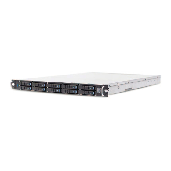
Chapter 1 Product Features Chapter 1� Product Features SB102-VG is a high density storage storage server that includes a mother board, a chassis, power supply, fan, and HDD backplane. For more information about our product, please visit our website at http://www.aicipc.com/en/index. -
Page 9: 1.2 Specifications
(W x D x H) management (with chassis ears) inches : 19 x 26 x 1.7 2 x USB 3.0 double-stack Type A Rear I/O AIC Server Board Virgo Motherboard 1 x external VGA port Processor Intel® Xeon® Scalable Processors Support... -
Page 10: 1�3 Features
1�3 Features SB102-VG is a reliable 1U storage server barebone with 10 hard drive disk bays that supports two Intel® Xeon® Scalable processors. This barebone consists of a Intel® Lewisburg C620 series Chipset, onboard baseboard management controller for system management and IPMI control and hot swap redundant fans. - Page 11 Major Components 650W 1+1 redundant power supply 5 x 4056mm dual rotor fans...
-
Page 12: Chapter 2� Hardware Setup
Processor heat s inks are not compatible with the Intel® Server Board S2600BP Product Family. Processor installation requires that the processor b e attached t o the processor heat sink using a specific processor carrier clip, prior to installation onto the server board. SB102-VG User's Manual... - Page 13 2.1.2 Processor Heat Sink Module and Processor Socket Assembly Each processor socket of the server board is pre-assembled with a loading mechanism that allows to secure the placement of the Processor Heat Sink Module (PHM) to the server board as shown below. SB102-VG User's Manual...
- Page 14 The PHM refers to the sub-assembly where the heat sink and processor are clipped together prior to installation onto the server board. The PHM consists of the components shown below. Processor Heat Sink Module (PHM) Sub-Assembly Processor Heatsink Module (PHM) SB102-VG User's Manual...
- Page 15 Failure t o tighten the heat sink screws i n the specified order may cause damage t o the processor socket assembly. Heat s ink screws should b e tightened t o 12 In-Lbs T orque o n indicated order on the top of the heat sink label. SB102-VG User's Manual...
- Page 16 Caution - Possible thermal damage. Avoid moving the heatsink after it has contacted the top of the CPU. Too much movement could disturb the layer of thermal compound, causing voids, and leading to ineffective heat dissipation and component damage. SB102-VG User's Manual...
-
Page 17: 2�2 System Memory & Sff-8643
In Virgo case, the lanes from CPU#0 are routed to pcie slots 1 and 5 and the onboard SFF-8643 the lanes from CPU#1 are routed to pcie slots 2 / 3 / 4 and the onboard SFF-8643 SB102-VG User's Manual... - Page 18 JDIMMD0 JDIMMH0 JDIMME0 JDIMMI0 JDIMMF0 JDIMML0 JDIMMC0 JDIMMK0 JDIMMB0 JDIMMJ0 JDIMMA0 CPU1 CPU0 CPU 0 CPU 0 CPU 1 CPU 1 JDIMM_L0 JDIMM_C0 8 DIMMs JDIMM_J0 JDIMM_A0 JDIMM_G0 JDIMM_D0 JDIMMG0 JDIMMD0 JDIMM_I0 JDIMM_F0 JDIMMH0 JDIMME0 JDIMMI0 JDIMMF0 SB102-VG User's Manual...
- Page 19 2.2.2 DIMM Installation Procedure Unlock a DIMM socket by pressing the retaining clips outward. Insert module vertically and press down until it snaps into place. Note: DIMM notch and socket bump must align as shown. DIMM notch SB102-VG User's Manual...
-
Page 20: 2�3 Removing And Installing The Top Cover
2.3.2 Removing the top cover Step 1 Press the release button on both sides of the enclosure. Step 2 Pull the top cover horizontally away from the front panel. Step 3 Lift the top cover upward to remove. SB102-VG User's Manual... -
Page 21: 2�4 Removing And Installing The Hard Disk Drive
Push the HDD tray lever and tray into the enclosure. 2.4.1.2 Removing the 2.5" hard disk drive tray Step 1 Press the release button on the HDD tray lever. Step 2 Pull the HDD tray out of the enclosure to remove. SB102-VG User's Manual... - Page 22 2.4.3 Installing and removing the hard disk drive into the tray Match the dimples on the tray to insert the HDD into the tray. Pull upward to remove the HDD from the HDD tray. Make certain that the HDD is not damaged during installation or removal process. SB102-VG User's Manual...
-
Page 23: 2�5 Removing And Installing The Fan Module
2�5 Removing and Installing the Fan Module 2.5.1 Installing/removing the fan module Insert or pull the fan module to install or remove the the fan module. Make certain to align the fan module to the appropriate slot. SB102-VG User's Manual... -
Page 24: 2�6 Removing And Installing The Power Supply Unit Module
Push the tray handle on the power suppl Module to install. 2.6.2 Removing the power supply unit module Step 1 Push the latch inward and hold the tray handle. Step 2 Pull the tray handle to remove. SB102-VG User's Manual... -
Page 25: 2�7 Removing And Installing The Riser Card
Step 1 Position the riser card onto the server board and into the enclosure. Step 2 Secure the thumb screw. 2.7.2 Removing the riser card Step 1 Loosen the thumb screw on the bracket that is connected to the riser card. Step 2 Remove the riser card. SB102-VG User's Manual...
Need help?
Do you have a question about the SB102-VG and is the answer not in the manual?
Questions and answers