Table of Contents
Advertisement
Quick Links
Advertisement
Table of Contents

Subscribe to Our Youtube Channel
Related Manuals for AIC SB303-GE


Summary of Contents for AIC SB303-GE
- Page 1 SB303-GE Storage Server Barebone User Manual Document Number: MAN-00106-A ...
-
Page 2: Table Of Contents
Chapter 1: Product Introduction ................ 5 1.1 General Information ........................ 5 1.2 System Specifications ....................1.3 Front View of SB303-GE ...................... 8 1.4 Rear View of SB303-GE..................... 1.5 Top View of SB303-GE ....................... 9 Chapter 2 : Hardware Setup .................. ... -
Page 3: Contents
Contents Chapter 3 : Motherboard Settings ................ 2 4 3.1 Motherboard layout ......................... 2 4 3.2 Motherboard Content List ...................... 2 4 3.2.1 Jumpers ......................... 25 3.2.2 Internal Connectors ..................... 26 3.2.3 Internal Connectors (Continue) ................27 3.2.4 Internal LEDs ........................ -
Page 4: Safety Information
Safety Information When installing, operating, or performing maintenance on this equipment, basic safety precautions, as listed below, should always be followed to reduce the risk of fire, electric shock, and personal injuries. Read and understand all instructions. Observe warnings and instructions marked on the product. -
Page 5: About This User's Manual
About This User’s Manual SB303 This document provides a detailed description of the -GE including: The General Features of the Product Hardware Setup Motherboard Settings BIOS Configuration and Settings BMC Configuration and Settings ... -
Page 6: Chapter 1: Product Introduction
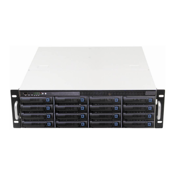
Chapter 1. Product Introduction 1.1 General Information SB303-GE , a 3U General Purpose Barebone, supports Dual-Core/Quad-Core/6-Core SB303-GE processors. has 16 x 3.5” + 2 x 2.5” size HDD bays in the rear side as system drive SB303-GE bays. harnesses MAX I/O™ technology, maximizing the usage of off-the-shelf expansion cards (up to 10) in the barebone. -
Page 7: System Specifications
1.2 System Specifications Dimensions (with chassis ears/protrusions) mm : 133 x 483 x 712 W x D x H inches : 5.25 x 19 x 28 Motherboard Motherboard Gemini (PSG‐M‐GEDP036D‐110) Processor Dual LGA1366 sockets to support two(2) Dual‐Core/Quad‐Core/6‐Core Intel® Xeon® processors Processor Support 5500/5600 series (Nehalem/Westmere) System Bus 1066/1333 MHz Chipset • Dual(2) Intel® 5520(TylersburgEP) Chipset Support • Intel® 82801JIR (ICH10R) Dual(2) Intel® 5520(TylersburgEP) System Memory •Twelve(12) DIMM slots support up to 192 GB of DDR3 800/1066/1333 MHz Registered ECC memory (recommended) / Unbuffered ECC SDRAM ... - Page 8 BIOS Features • ACPI 1.0/2.0/3.0 • IPMI KCS interface • PXE 2.0 • SMBIOS 2.0 • WOL • Serial console redirection • AC loss recovery On‐Board Devices SATA Built‐in Intel® ICH10R SATA2 controller with RAID support Aspeed AST2050 BMC • Intelligent Platform Management Interface 2.0 (IPMI 2.0) IPMI • iKVM, Media Re‐direction, IPMI over LAN, Serial over LAN • SMASH support • Two(2) Intel® 82571EB (Ophir) PCIe Dual‐port GbE controller; external Network Controllers • Intel® 82574L (Hartwell) PCIe Single‐port GbE controller; external (BMC Management) • Intel® 82567LM (Boazman) GLCI on ICH10R Single‐port GbE PHY; external Graphics Aspeed AST2050 graphics controller • 8MB of memory • 1600 x 1200 @ 60 Hz Super I/O Winbond W83627DHG Rear I/O 6 (six) x one gigabit (Gb) Ethernet connectors LAN 1(one) x 10 Gb Ethernet port USB 2 (two) x USB ports VGA 1 (one) x VGA port Serial Port 1 (one) x DB‐9 serial port Power Supply 1000 W Two hot‐swap redundant AC power supplies Power Supply ...
-
Page 9: Front View Of Sb303-Ge
1.3 Front View of SB303-GE Icon Color Controls Icon System Behavior LED System Behavior Solid: System On Power LED Green Power ON/OFF Push for Power On or Off Off: System Off System ID System Identification Blue System ID Push for ID LED On or Off LED Blink: Activity Alert LED Red Light: System Alert System Reset Push for System Reset Non‐maskable interrupt; Light: Link ... -
Page 10: Top View Of Sb303Ge
1.5 Top View of SB303GE The barebone server includes the basic components shown below. Hot‐swap HDD Trays Full Length Expansion Card Bracket Gemini Motherboard Full Length Power Supply Expansion Card Bracket Rear I/O ... -
Page 11: Chapter 2. Hardware Setup
Chapter 2. Hardware Setup This section SB303-GE appliance is installed and is operational. 2.1 Chassis Cover 2.1.1 Removing the Chassis Cover 1. Release the two screws on the rear panel. 2. Pull the cover back to open the rear cover from chassis. -
Page 12: Central Processing Unit (Cpu)
2.2 Central Processing Unit (CPU) 2.2.1 Installing the CPU 1. Press the load lever to release the load plate. 2. Lift the load plate. 3. Remove the processor protective cover from CPU socket. ... - Page 13 4. Align the processor cutouts against the socket notches. 5. Close the load plate & load lever. ...
-
Page 14: Installing The Cpu Heatsink
2.2.2 Installing the CPU Heatsink To install the CPU heatsink: 1. Place the heatsink on top of the CPU, ensuring that the four fasteners match the holes on the motherboard. 2. Tighten the four screws in a diagonal sequence, a couple of turns at a time, until all four screws are secure and the heatsink is securely fastened to the chassis. -
Page 15: System Memory
2.3 System Memory This server board supports up to twelve DDR3 800/1066/1333 Registered ECC SDRAM (recommended)/ Unbuffered ECC SDRAM. 1. Populate DIMMs in the following order: DIMM DIMM arrangement Numbers 2 DIMMs CPU0 DIMM 0 CPU1 DIMM 0 4 DIMMs CPU0 DIMM 0 CPU0 DIMM 0 CPU1 DIMM 0... - Page 16 CPU0 DIMM 0 8 DIMMs CPU0 DIMM 0 CPU0 DIMM 0 DIMM 1 CPU1 DIMM 0 CPU1 DIMM 0 CPU1 DIMM 0 DIMM 1 CPU0 DIMM 0 CPU0 DIMM 0 10 DIMMs CPU0 DIMM 0 DIMM 1 DIMM 1 CPU1 DIMM 0 CPU1 DIMM 0 CPU1 DIMM 0...
-
Page 17: Drive Bays
2.4 Drive Bays 2.4.1 Installing or Replacing 3.5” Hot-swap SAS/SATA HDD 1. Release a drive tray by pressing the unlock button and pinching slightly the lock lever and pulling out the drive tray. 2. Firmly hold the tray lever and pull the drive out of the bay. 3. -
Page 18: Installing Or Replacing 2.5" Hot-Swap Sas/Sata Hdd
2.4.2 Installing or Replacing 2.5” Hot-swap SAS/SATA HDD or SSD 1. Release a drive tray by pressing the unlock button and pinching the lock lever slightly and pulling out the drive tray. 2. Firmly hold the tray lever and pull the drive out of the bay. 3. -
Page 19: Mb Tray
2.5 MB Tray 2.5.1 Removing the MB Tray 1. Remove the screws on the right side of rear panel. 2. Remove the screws on the bottom of barebone. 3. Remove the power housing screws on the left side of rear panel. 4. -
Page 20: Riser Card
2.6 Riser Card 1. RISER CARD PN (PSG CODE) DESCRIPTION PSG-RC-GEHO-70-212 (PE3U01) Gemini 3U Gold finger PCIe Gen2 X16 to 2 PCIe X16 + 3 PCIe X8(1 X8 Gen2 + 1 X4 Gen2 + 1 X4 Gen1) RISER CARD DIAGRAM Front view: ... -
Page 21: Expansion Slot
2. MB DIP switch setting 1 PE5 PE6 SW1 ON OFF ON ON OFF OFF X 16 X 8 1 6 PE9 PEA PEB PEC PED PEE PEF PEG PEH PEI SW2 ... - Page 22 2.7.2 Installing an External PCIE Card to the Riser Card 1. Remove the screw to release the bracket. To install a full length expansion card, please remove the half length bracket. 2. Insert the full length PCIE card. ...
-
Page 23: System Fans
2.8 System Fans 2.8.1 Removing or Replacing the System Fans 1. Release the thumb screw on the fan module. Hold the fan lever firmly and pull the fan out of the server chassis to remove the fan module from the server chassis. -
Page 24: Chapter 3 : Motherboard Settings
Chapter 3. Motherboard Settings This section describes the jumpers, internal connectors, and internal LEDs setting on Gemini PGS-M-GEDP036D-110 motherboard. We will show the motherboard layout and important jumper settings of the system. 3.1 Motherboard Layout 3.2 Motherboard Content List Jumpers Location Internal Connectors... -
Page 25: Jumpers
3.2.1 Jumpers NORMAL CLEAR CLEAR CMOS OPEN INVALID CPU0 / CPU1JTAG JTAG BY PASS J43 / J41 BYPASS NORMAL CPU0 / CPU1 VRM ENABLE J12 / J19 TEST NORMAL DISABLE VGA DISABLE ENABLE DISABLE AST ARM ENABLE RESET AST ARM RESET NORMAL PCIe Strapping configuration O F F... -
Page 26: Internal Connectors
3.2.2 Internal Connectors 1.USB5V 2.USB5V 3.USBD- 4.USBD- 5.USBD+ 6.USBD+ J16 / J25 7.GND 8.GND 9.GND 10.NC 1.GND 2.3.3V 3.I2CSCL 4.I2CSDA 5.PWM1 6.FAN1_TACH FAN BOARD 7.PWM2 8.FAN2_TACH J15 / J63 CONNECTOR 9.PWM3 10.FAN3_TACH 11.PWM4 12.FAN4_TACH 13.FAN6_TACH 14.FAN5_TACH 15.GND 16.GND 1.FAN7_TACH 2.FAN8_TACH 3.FAN1_TACH 4.PWM1... -
Page 27: Internal Connectors (Continue)
3.2.3 Internal Connectors (continue) 1. GND 1516 GREEN DATA BLUE VGA HEADER 10.H_SYNC 11.V_SYNC 12.DVD_5V 13.GND 14.GND 15.GND 16.CLK 1.KB_DATA 2.+5V 3.KB_CLK KB/MS 4.MS_CLK 5.MS_DATA 6.GND 1.DSR# 2.DCD#G 3.RTS# 4.RXD UART/COM2 5.CTS# 6.TXD 7.RI# 8.DTR#... -
Page 28: Internal Leds
1.+1.5V_DDR3_CPU0 2.GND 3.VCCP_CPU0 4.GND 5.VTT_CPU0 6.GND VOLTAGE TEST 7.+3.3V 8.GND POINT GROUP A 9.+3.3V_DUAL 10.GND 11.+5V 12.GND 13.+1.5V 14.GND 14.GND 16.GND 1.GND 2.NC BMC GPIO 3.GPIOE7 4.GPIOB7 5.GPIOE6 6.GPIOB2 3.2.4 Internal LEDs LED ON=LAN LINK LED BLINK=ACTIVE 1.GbE5 LED# 2.GbE5 LED+ 3.GbE4 LED# 4.GbE4 LED+... -
Page 29: Chapter 4 : Bios Configuration And Settings
Chapter 4. BIOS Configuration and Settings 4.1 BIOS Setting 1. Press DEL to run the setup procedure. 2. There will be a message “Entering SETUP” displayed on the diagnostics screen. ... - Page 30 3. Identify the BIOS Version 4. Load Optimal Default setting 5. Save the setting and exit the BIOS setup utility. ...
-
Page 31: Updating Bios
1. AFUDOS is a BIOS update utility with command line interface that works in DOS environment. 2. The latest BIOS version is available from the FAE or AIC website. 3. Enter “flash” at the DOS command line. 4. Reboot the system after the update. -
Page 32: Chapter 5 : Bmc Configuration And Settings
Chapter 5. BMC Configuration and Settings Insert BMC IP LAN into the BMC LAN port. There are two methods to setup BMC IP: 5.1 Method 1 (Use the BIOS setup) 1. BIOS SETUP -> Advance -> IPMI configuration -> Set LAN configuration ... - Page 33 Input IP address. Set IP static. Input subnet mask address. ...
-
Page 34: Method 2 (Use A Dos Tool - Syscheck)
5.2 Method 2 (Use a Dos tool - Syscheck) 1. Type : sc –lanset. 2. Modify IP setting. ... - Page 35 3. Input IP address. 4. Input submask address. Below IP address is an example using a default IP setting. User is allowed to change the IP address for realistic use. 5. Finish BMC IP configuration. ...
-
Page 36: Connect To Bmc
5.3 Connect to BMC Below IP address is an example using default IP setting. User is allowed to change the IP address for realistic use. 1. Open the browser then type default BMC IP address: 192.168.22.22 2. Use the default user name and password for first-time login to ASTER. Field: Default UserName:... - Page 37 3. Information of ASTER firmware. 4. Server Health - Sensor Readings: 5. Configuration Please refer to AIC BMC User Guide for more information on AIC BMC. ...
- Page 38 Mouse Mode setting: For Windows OS environment, set mode to absolute. For Linux OS environment, set mode to relative. Remote Control: Environmental setting: ...
-
Page 39: Updating Bmc Firmware
3. Execute a.bat batch file to update the BMC firmware Example: A:>cd AQUAN120 A:\ AQUAN120>a.bat This is just an example. The latest BMC firmware version is available from the FAE or AIC website. After update BMC firmware, please power off and then power on system. ... -
Page 40: Updating Bmc Configuration
3. Execute the config.bat batch file to update config file Example: A :> cd G107NC01 A:\ G107NC01>config.bat This is just an example; the latest BMC configuration version is available from the FAE or AIC website. 4. After update config file, please power off and then power on system. ... -
Page 41: Chapter 6. Technical Support
Chapter 6. Technical Support TAIWAN Tel: +886.3.313.8386 Fax: +886.3.313.8377 Email Technical Support: support@aicipc.com JAPAN Tel: +81.43.202.8380 Fax: +81.43.202.8381 Email Technical Support: support@aicipc.com CHINA Tel: +021.54961421, +021.54961422 Fax: Extension: 608 Email Technical Support: support@aicipc.com AMERICA - West coast ... - Page 42 Note ...
Need help?
Do you have a question about the SB303-GE and is the answer not in the manual?
Questions and answers