
Related Manuals for Eneo MSM-42F0037MPA


Summary of Contents for Eneo MSM-42F0037MPA
-
Page 1: User Manual
User Manual 1/2.8” HD Board Camera, Colour, 1920x1080, WDR, 12VDC MSM-42F0037MPA MSM-42F0028M0A... -
Page 2: Safety Precaution
ULTRA CLEAR RESOLUTION CAMERA Safety Precaution To prevent fire or shock hazard, do not expose the unit to rain or moisture. To prevent electric shocks and risk of fire hazards, do NOT use other than specific power source. CAUTION: TO REDUCE THE RISK OF ELECTRIC SHOCK, DO NOT REMOVE COVER (OR BACK). - Page 3 ULTRA CLEAR RESOLUTION CAMERA Safety Precaution NOTICE The image used in this instruction manual are processed to help comprehension and may differ from actual video of the camera. Avoid installing areas where has shock or vibration which results in the problems. Pay attention to safety when laying the connection cable and observe that the cable is not subjected to heavy loads, kinks or damage and no moisture can get in.
-
Page 4: Table Of Contents
ULTRA CLEAR RESOLUTION CAMERA Contents p.03~04 Safety Precaution p.05 Contents p.06 Features p.07 Composition p.07 Dimensions p.08~09 Installation Instructions p.10~24 Operating Instructions p.25 Specifications... -
Page 5: Features
• TVI mode / AHD mode / CVI mode, Video Transmission Distance over Coax.; 500M • Lens selectable > MSM-42F0037MPA : f=3.7mm Pin-hole lens > MSM-42F0028M0A : f=2.8mm Fixed lens • Sensitivity of Color 0.08 Lux, B/W 0.005 Lux • True WDR(Wide Dynamic Range) 30/25fps •... -
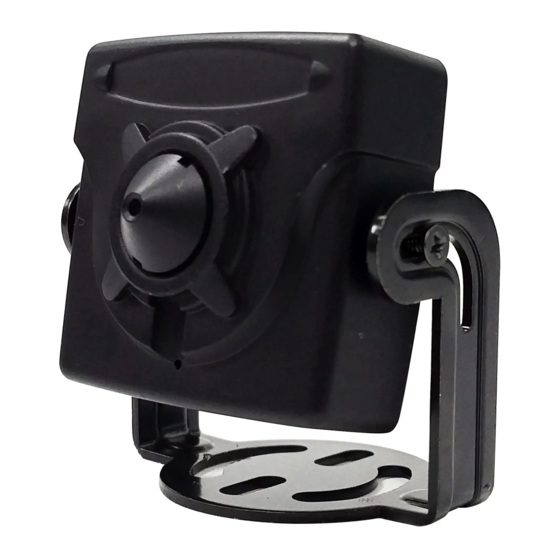
Page 6: Composition
ULTRA CLEAR RESOLUTION CAMERA Composition Mini JIG OSD Control board Operating MSM-42F0037MPA MSM-42F0028M0A Instruction Mounting Screw: BH 3x10mm (2pcs) Dimensions (unit : mm) 43.5 21.5 37.8 MSM-42F0037MPA 37.8 MSM-42F0028M0A... -
Page 7: Installation Instructions
ULTRA CLEAR RESOLUTION CAMERA Installation Instructions 1. Place the camera bracket at the installation position and fix it by using mounting screws. 2. Connect the power/video cable then setup the camera menu if neccessory. (Use the mini jig OSD control board) 3. -
Page 8: Power Supply Connections
ULTRA CLEAR RESOLUTION CAMERA Installation Instructions Power Supply Connections Camera can be operated with the regulated or unregulated 12VDC but the regulated power supply of 12VDC is recommended. Camera is protected from the damage by the reverse connection of polarity. ※SDI OUTPUT (Yellow) ANALOG OUTPUT... -
Page 9: Operating Instructions
ULTRA CLEAR RESOLUTION CAMERA Operating Instructions OSD menu Table Camera setup menu can be accessed and controlled by OSD controller. • EXIT : Enters ‘EXIT’ menu with save current setting or without save. • RETURN : Returns to the previous menu. MENU SUB MENU CONFIGURATION... - Page 10 ULTRA CLEAR RESOLUTION CAMERA Operating Instructions FLIP OFF, ON IMAGE D-WDR OFF, LOW, MIDDLE, HIGH MODE (AUTO, MANUAL) OFF, ON DEFOG LEVEL (LOW, MIDDLE, HIGH) PRIVACY OFF, ON ZONE NUM, ZONE DISP, H/V-POS, H/V- SIZE, Y LEVEL, CB/CR LEVEL, TRANS OFF, ON DET WINDOW WINDOW ZONE, WINDOW USE, DET...
- Page 11 ULTRA CLEAR RESOLUTION CAMERA Operating Instructions OSD menu Startup MENU V0. XX 1. LENS MANUAL 2. FOCUS ASt. 3. EXPOSURE 4. BACKLIGHT COLOR 5. DAY&NIGHT 6. COLOR MIDDLE 7. 3D-NR 8. IMAGE 9. MOTION A. SYSTEM SAVE B. EXIT 1. LENS (Default: MANUAL) Lens can be selected either DC or MANUAL lens.
- Page 12 ULTRA CLEAR RESOLUTION CAMERA Operating Instructions 3. EXPOSURE 3. EXPOSURE BRIGHTNESS llllllllllllllllllllll SHUTTER AUTO SENS-UP llllllllllllllllllllll RETURN 3-1. BRIGHTNESS Adjusts the brightness of video (0~20). 3-2. SHUTTER Selects AUTO or set manually. If SHUTTER set to MANUAL modes, SENS-UP mode is inactivated. 3-2-1.
- Page 13 ULTRA CLEAR RESOLUTION CAMERA Operating Instructions 4. BACKLIGHT Compensates the video image to cut out the highlight area with mask or control the contrast of video. It can be set the compendation level or areas. LEVEL llllllllllllllllllllll COLOR RETURN 4-1. HLC (High Light Compensation) Cuts out the highlight area with mask and excludes it from compensation.
- Page 14 ULTRA CLEAR RESOLUTION CAMERA Operating Instructions MODE WINDOW ZONE WEIGHT WINDOW USE MIDDLE RETURN H-POS V-POS H-SIZE V-SIZE RETURN 4-3. WDR (Wide Dynamic Range) WDR is extended the gain range of the video that is mostly useful if camera takes a simultaneous picture of both indoor and outdoor nearby window. It improves contrast of the picture in outdoor scenery as well as indoor.
- Page 15 ULTRA CLEAR RESOLUTION CAMERA Operating Instructions 5. DAY & NIGHT DAY/NIGHT is used to control the setting during day-time and night-time operation. Select the mode according to the light condition and the camera types. MENU V0. XX 1. LENS MANUAL 2.
- Page 16 ULTRA CLEAR RESOLUTION CAMERA Operating Instructions 5-2-4. AGC MARGIN : Sets the gap level switching from/to DAY(color) or NIGHT(B/W). 5-2-5. DELAY : D→N DELAY is time in second while camera maintains its status before Day to Night switches. DELAY can avoid the unwanted/frivolous switching by a short term lights such as light from the passing car.
- Page 17 ULTRA CLEAR RESOLUTION CAMERA Operating Instructions 6. COLOR 6. COLOR AUTO COLOR GAIN llllllllllllllllllllll RETURN 6-1. AWB (Auto White Balance) Automatically tracks the changes of color temperature and continuously adjusts the white balance. AUTO, AUTOext, PRESET and MANUAL modes are available. 6-1-1.
- Page 18 ULTRA CLEAR RESOLUTION CAMERA Operating Instructions 7. 3D-NR (Digital Noise Reduction) DNR function improves picture quality by filtering out signal noise which is generated under the low light conditions. Sets off, low, middle or high level. 3DNR(3-dimensional noise reduction) which reduces the noise by the multi frames.
- Page 19 ULTRA CLEAR RESOLUTION CAMERA Operating Instructions 8-1. SHARPNESS Sets the Sharpness level 0~10. Increases or decreases the sharpness of the picture. Too much sharpness can make image harsh and show more noise as well as line flicker at the edge of object in the picture. 8-2.
- Page 20 ULTRA CLEAR RESOLUTION CAMERA Operating Instructions PRIVACY ZONE NUM ZONE DISP H-POS V-POS H-SIZE V-SIZE Y-LEVEL llllllllllllllllllllll CB LEVEL llllllllllllllllllllll CR LEVEL llllllllllllllllllllll TRANS RETURN 8-7-4. H-SIZE, V-SIZE : Adjusts the mask size using H, V direction which you selected zone. 8-7-5.
- Page 21 ULTRA CLEAR RESOLUTION CAMERA Operating Instructions 9. MOTION DET WINDOW DET WINDOW WINDOW ZONE DET TONE WINDOW USE MDRECT FILL DET H-POS SENSITIVITY llllllllllllllllllllll DET V-POS MOTION OSD DET H-SIZE TEXT ALARM DET V-SIZE RETURN RETURN 9-2. DET TONE Sets the detection zone 0 to 4 display types which window use setting ON. 0 : Set the 100% opacity level of video background except detection window zone.
- Page 22 ULTRA CLEAR RESOLUTION CAMERA Operating Instructions A. SYSTEM Sets the system related functions. A. SYSTEM OUTPUT RESOLUTION 1080 25P TV SYSTEM EU(PAL) LANGUAGE CAM TITLE RESET RETURN HD-ANALOG OUTPUT SDI OUTPUT MAIN OUTPUT HD-SDI SDI OUTPUT HD-SDI SDI OUTPUT Y GAIN NOT USED ANALOG OUT0 TVI MODE...
- Page 23 ULTRA CLEAR RESOLUTION CAMERA Operating Instructions If CVBS video is enabled through ANALOG OUT0 or Sub-out port, WDR and 3D-NR functions are disabled in all video outputs. It should be considered when installer adjusts the video with installation monitor via CVBS video signal. A-2.
-
Page 24: Specifications
ULTRA CLEAR RESOLUTION CAMERA Specifications ITEM MSM-42F0037MPA MSM-42F0028M0A Imaging Sensor 1/2.8” Sony 2Mega pixel CMOS STARVIS Sensor Effective Pixels 1920(H) x 1080(V) x 25p Scan Frequency 25Hz(V), 18.75Khz(H) / Progressive Video Format HD] 16:9, 1080p@25fps CVBS] 16:9 (PAL) Video Output EX-SDI 1.0, 2.0 /HD-SDI / TVI mode/ AHD mode/ CVI mode/ CVBS... - Page 25 VIDEOR E. Hartig GmbH Exclusive distribution through special- ised trade channels only. VIDEOR E. Hartig GmbH Carl-Zeiss-Straße 8 63322 Rödermark/Germany Tel. +49 (0) 6074 / 888-0 Technical changes reserved Fax +49 (0) 6074 / 888-100 www.videor.com...
Need help?
Do you have a question about the MSM-42F0037MPA and is the answer not in the manual?
Questions and answers