Table of Contents
Advertisement
Available languages
Available languages
Quick Links
Download this manual
See also:
User Manual
Advertisement
Chapters
Table of Contents

Subscribe to Our Youtube Channel
Related Manuals for Eneo MCB-72M2712M0A


Summary of Contents for Eneo MCB-72M2712M0A
-
Page 1: Quick Installation Guide
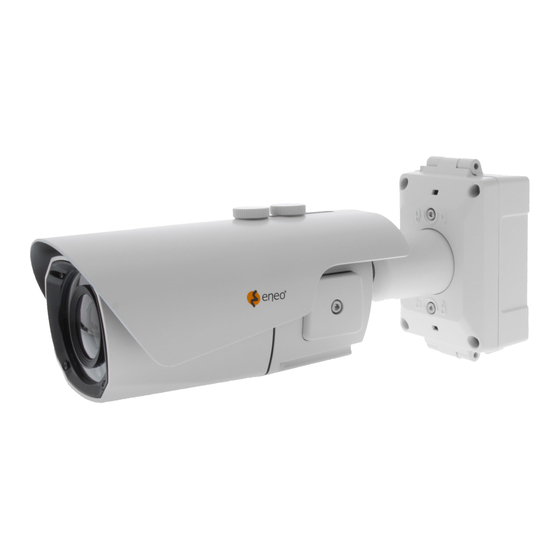
Quick Installation Guide 1/2,8” HD Camera, Day&Night, 1920x1080, Infrared, WDR, 2,7- 12mm, 12/24V, IP67 MCB-72M2712M0A... -
Page 2: Table Of Contents
Table of content Parts supplied .......................5 Part names ........................6 Installation instructions ....................7 Using Grommet ..................................7 Recommended cable length into the Junction box base ..................7 Pan & Tilt adjustments ..............................10 Operating instructions ....................12 Using OSD controller..............................12 Description of the joystick operation ....................... 12 Description of the Motorized ZOOM&Focus adjustment .............. -
Page 3: Safety Instructions
Safety instructions General safety instructions • Before switching on and operating the system, first read this safety advice and the operating instructions. • Keep the operating instructions in a safe place for later use. • Installation, commissioning and maintenance of the system may only be carried out by authorised individuals and in accordance with the installation instructions - ensuring that all applicable standards and guidelines are followed. - Page 4 Class A device note This is a Class A device. This device can cause malfunctions in the living area; in such an event, the operator may need to take appropriate measures to compensate for these. WEEE (Waste Electronical & Electronic Equipment) Correct Disposal of This Product (Applicable in the European Union and other European countries with separate collection systems).
-
Page 5: Parts Supplied
Parts supplied • Camera • Operating Instruction • Mounting Template • Plastic Anchor: 6 x 30mm (4x) • Mounting Screw: 4 x 30mm (4x) • Hex Wrench: 3mm (1x) • Hinge Pin (1x) • Cable Tie (2x) • Grommet (2x) •... -
Page 6: Part Names
Part names Sunshield bolt Sunshield Junction Box Top Junction Box Base Bracket Body Case Dual window Hinge Pin 2x Lock/Unlock Screw 2x Water drain Inside of Opening Cover Please close the cover after setting up and OSD Control Joy Stick tighten it properly. -
Page 7: Installation Instructions
Installation instructions Using Grommet Tear off the cocks of grommets properly and pull up the grommet so that sealing can wrap the cable properly as illustrated. If it doesn’t wrap the cable properly,it could cause the water leakage problem. Recommended cable length into the Junction box base •... - Page 8 Install the mount onto a strong structure. Prepare the Junction box base and the accessaries for installation. 1. Locate the mounting template at the installation position and drill the ceiling or wall if needed. 2. Route the Power/Video cables through the grommets from the wall. Insert the grommets onto the Junction box base.
- Page 9 Hinge pin Junction Box Top 8. Cover the Junction box top and tighten with assembly screws (4pcs). * Caution: If assembly screws are not firmly assembled, it causes water leakage. 9. Set the camera’s orientation and tighten the Lock/Unlock screws using hex wrench.
-
Page 10: Pan & Tilt Adjustments
Pan & Tilt adjustments • Unlock the screw on the camera bracket through using the torque wrench supplied • Set the camera’s viewing angle then lock the screw on the bracket. 1. Pan limit: Pan is limited to +/- 90°. 2. - Page 11 Adjustment of viewing angle with a bracket Hex wrench...
-
Page 12: Operating Instructions
Operating instructions Using OSD controller Setup menu can be accessed and controlled by OSD control joy stick on the side of cam- era unit. Five commands are available with the joy stick. Cover Open SUB-OUT OSD Control Joy Stick Video Sub-out Connector ZOOM Description of the joystick operation 1. -
Page 13: Osd Menu Table
2. ▼ : Zoom Out 3. ◄ : Focus Near 4. ► : Focus Far ANALOG OUT0 should be set to TVI MODE, AHD MODE or CVI MODE to get CVBS video in sub-out. If it is set to CVBS, there is no CVBS video in sub-out port. (SYSTEM> OUTPUT>... - Page 14 MENU SUB MENU CONFIGURATION BRIGHTNESS 0~20 AUTO MODE (INDOOR, OUTDOOR, DEBLUR) 1/30(1/25), 1/60(1/50), 1/120(100), 1/250(200), 1/500(400), MANUAL SHUTTER 1/1000(800), 1/2000(1600), 1/4000(3200), 1/8000(6400), (SPEED) EXPOSURE 1/15000(12800), 1/30000(25600) FLICKERLESS SENS-UP OFF, x2, x4, x8, x16, x32 0~10 LEVEL, COLOR H/V-POS, H/V-SIZE WINDOW ZONE/USE, H/V-POS, BACKLIGHT H/V-SIZE MODE...
- Page 15 MENU SUB MENU CONFIGURATION WINDOW ZONE, WINDOW USE, DET H/V-POS, DET WINDOW DET H/V-SIZE DET TONE MDRECT FILL OFF, ON MOTION OFF, ON SENSITIVITY 0~10 MOTION OSD OFF, ON TEXT ALARM OFF, ON SDI OUTPUT HD-SDI, EX-SDI 1.0, EX-SDI 2.0, OFF OUTPUT ANALOG OUT0 TVI MODE, AHD MODE, CVBS, CVI MODE...
-
Page 16: Further Information
Further information The manual is also available from the eneo web site at www.eneo-security.com. - Page 17 Inhaltsverzeichnis Lieferumfang .......................20 Bezeichnungen von Gerätekomponenten ...............21 Installationsanweisungen ..................22 Verwendung der Tülle ..............................22 Empfohlene Kabellängen für die Anschlussbox ....................22 Einstellung von Schwenkung und Neigung ......................25 Betriebsanleitung .......................27 Bildschirmmenü-Steuerung verwenden ....................... 27 Beschreibung der Joystick-Bedienung ..................... 27 Beschreibung der Einstellung für das motorisierte Zoom und Fokus ......... 27 Bildschirmmenü-Übersicht ............................
- Page 18 Sicherheitsanweisungen Sicherheitshinweise allgemein • Bevor Sie das System anschließen und in Betrieb nehmen, lesen Sie zuerst diese Sicherheitshinweise und die Betriebsanleitung. • Bewahren Sie die Betriebsanleitung sorgfältig zur späteren Verwendung auf. • Montage, Inbetriebnahme und Wartung des Systems darf nur durch dafür autorisierte Personen vorgenom- men und entsprechend den Installationsanweisungen - unter Beachtung aller mitgeltenden Normen und Richtlinien - durchgeführt werden.
- Page 19 • Bei abgedunkelter Umgebung und direktem Blick in den IR-Scheinwerfer ist ein Sicherheitsabstand von > 1 m zum Scheinwerfer einzuhalten. • Unsichtbare LED Strahlung nicht direkt mit optischen Instrumenten (z.B. Lupe, Vergrößerungsglas oder Mikroskop) betrachten, da dies Augen gefährden kann, LED Klasse 1M. •...
-
Page 20: Lieferumfang
Lieferumfang • Kamera • Betriebsanleitung • Bohrschablone • Kunststoffdübel: 6 x 30mm (4x) • Befestigungsschraube: 4 x 30mm (4x) • Inbusschlüssel: 3 mm (1x) • Scharnierstift (1x) • Kabelbinder (2x) • Tülle (2x) • Video Sub-out Kabel (1x) • Kabelbefestigungsplatte mit Befestigungsschraube •... -
Page 21: Bezeichnungen Von Gerätekomponenten
Bezeichnungen von Gerätekomponenten Bolzen für Sonnenschutzdach Sonnenschutzdach Die Abdeckung der Anschlussbox Basis der Anschlussbox Kamerahalterung Kameragehäuse Doppelglasiges Fenster Scharnierstift 2x Schraube zum 2x Wasserablauf Verriegeln/Entriegeln Anschlüsse unter der Seitenabdeckung Bitte bringen Sie die Joystick zur Abdeckung an den Bildschirmmenü-Steuerung ursprünglichen Platz und ziehen Sie diese fest. -
Page 22: Installationsanweisungen
Installationsanweisungen Verwendung der Tülle Entfernen Sie die Spitzen der Kabeltüllen und ziehen Sie das Ende der Tülle aus, sodass das durchgeführte Kabel, wie in der Abbildung dargestellt, fest umschlossen wird. Wenn die Tülle das Kabel nicht fest umschließt, könnte Feuchtigkeit ins Innere der Box eindringen. - Page 23 Befestigen Sie die Montagebasis an einer tragfähigen Struktur. Bereiten Sie die Basis der Anschlussbox und das Zubehör für die Installation vor. 1. Halten Sie die Bohrschablone an die Installationsstelle und bohren Sie die Löcher in Decke oder Wand, falls erforderlich. 2.
- Page 24 7. Schließen Sie die Netz- und Video-Kabel von der Kamera an. Befestigen Sie die Netz- und Videokabel von Kamera an der Basis der Anschlussbox mithilfe der mitgelieferten Schraube. Scharnierstift Die Abdeckung der Anschlussbox 8. Bringen Sie die Abdeckung der Anschlussbox an und ziehen Sie diese mit den Verbindungsschrauben (4 Stück) fest.
-
Page 25: Einstellung Von Schwenkung Und Neigung
9. Richten Sie die Kamera im richtigen Winkel aus und ziehen Sie die Schrauben zum Verriegeln/Entriegeln mit dem Inbusschlüssel fest. 10. Öffnen Sie bei Bedarf die Seitenabdeckung und schließen Sie das Sub-out-Kabel für die Einstellungen im Bildschirm-Menü an. 11. Nachdem alle Einstellungen gemacht wurden, bringen Sie die Abdeckung wieder an und ziehen Sie diese fest. - Page 26 3. Drehwinkel (horizontale Bildausrichtung): Der Drehwinkel ist begrenzt auf max. +/-90°. Anpassung des Betrachtungswinkels mit einem Halter Inbusschlüssel...
-
Page 27: Betriebsanleitung
Betriebsanleitung Bildschirmmenü-Steuerung verwenden Zugriff und Steuerung des Konfigurationsmenüs können über den Joystick zur Bild- schirmmenü-Steuerung an der Kamera und einen Service Monitor erfolgen. Fünf Befehle stehen mit dem Joystick zur Verfügung. Abdeckung öffnen SUB-OUT Joystick zur Bildschirmmenü-Steuerung Video Sub-out Anschluss ZOOM Beschreibung der Joystick-Bedienung 1. -
Page 28: Bildschirmmenü-Übersicht
2. ▼ : Herauszoomen 3. ◄ : Fokus nah 4. ► : Fokus fern ANALOG OUT0 sollte auf TVI MODE (TVI-MODUS), AHD MODE (AHD-MODUS) oder CVI MODE (CVI-MODUS) eingestellt sein, um das FBAS-Signal auf Sub-Out zu empfangen. Wenn hier CVBS (FBAS) eingestellt ist, wird kein FBAS-Signal auf Sub-Out empfangen. (SYSTEM>... - Page 29 MENÜ SUB MENU CONFIGURATION AF-MODE (AF-MODUS) ZOOMPUSH, MANUAL (MANUELL) MODE CHANGE ENABLED (AKTIVIERT), DISABLED (DEAKTIVIERT) (MODUSÄNDERUNG) SCANNING (SCANNEN) HALF, FULL (HALB, VOLL) ZOOM/FOCUS ONEPUSHAF SYNC TDN ON, OFF (EIN, AUS) INITIAL (INITIALISIERUNG) BRIGHTNESS 0-20 (Helligkeit) AUTO MODE (MODUS) (INDOOR, OUTDOOR, DEBLUR) MANUAL 1/30(1/25), 1/60(1/50), 1/120(100), 1/250(200), 1/500(400), SHUTTER (Verschluss)
- Page 30 MENÜ SUB MENU CONFIGURATION TVI MODE (TVI- MODUS), AHD MODE ANALOG OUT0 (AHD-MODUS), CVBS (FBAS), CVI MODE (CVI-MODUS) TVI MODE ANALOG OUT0 0-10 (TVI-MODUS) AHD MODE 0-10 (AHD-MODUS) MAIN OUTPUT SHARPNESS (Schärfe) CVI MODE (HAUPTAUSGANG) 0-10 (CVI-MODUS) ANALOG OUT1 CVBS (FBAS) ANALOG OUT1 SDI (SDI) &...
-
Page 31: Weitere Informationen
Weitere Informationen Dieses Handbuch ist auch auf der eneo-Webseite unter www.eneo-security.com verfügbar. - Page 32 Contenu Matériel livré .......................35 Noms des pièces ......................36 Instructions d'installation ..................37 Utilisation de passe-câble ............................37 Longueur de câble recommandée dans l'embase de la boîte de jonction ..........37 Réglages Panoramique/Inclinaisons ........................40 Mode d'emploi ......................42 Utilisation d'une commande OSD ..........................42 Description du fonctionnement de la manette de contrôle ............
- Page 33 Instructions de sécurité Consignes de sécurité générales • Avant de brancher et de mettre en service le système, veuillez lire d'abord ces consignes de sécurité ainsi que la notice d'instructions. • Conservez soigneusement la notice d'instructions en vue d'une utilisation ultérieure. •...
- Page 34 • Une distance de sécurité > 1 m doit être respectée par rapport au projecteur dans un environnement sombre, quand on regarde directement dans le projecteur IR. • Les rayons invisibles des LED ne doivent pas être observés directement avec des instruments optiques (par ex.
-
Page 35: Matériel Livré
Matériel livré • Caméra • Mode d'emploi • Gabarit de perçage • Cheville en plastique : 6 x 30 mm (4x) • Vis de montage : 4 x 30 mm (4x) • Clé six pans : 3 mm (1x) • Axe de charnière (1x) •... -
Page 36: Noms Des Pièces
Noms des pièces Boulon du pare-soleil Pare-soleil Partie supérieure de la boîte de jonction Embase de la boîte de jonction Support Corps de boîtier Double vitre Axe de charnière 2x vis de blocage/déblocage 2x orifices d'évacuation de l'eau Intérieur du couvercle amovible Fermer le couvercle après le réglage et le Manette de commande OSD... -
Page 37: Instructions D'installation
Instructions d'installation Utilisation de passe-câble Enlever correctement les bouchons des passe-câble et remonter le passe-câble de telle façon que le joint d'étanchéité entoure le câble correctement, tel que décrit sur l'illustra- tion. Si le joint n'enveloppe pas le câble correctement, cela peut provoquer un problème d'infiltration d'eau Longueur de câble recommandée dans l'embase de la boîte de jonction... - Page 38 Installer le support sur une structure solide. Préparez l'embase de la boîte de jonction et les accessoires pour l'installation. 1. Placer le gabarit de montage à la position de montage et faire un trou dans le plafond ou dans le mur si nécessaire. 2.
- Page 39 7. Connecter les câbles d'alimentation/vidéo de la caméra comme l'indique l'illustra- tion. Fixer les câbles d'alimentation/vidéo de la caméra à l'embase de la boîte de jonction en utilisant la vis fournie. Axe de charnière Partie supérieure de la boîte de jonction 8.
-
Page 40: Réglages Panoramique/Inclinaisons
9. Régler l'orientation de la caméra et serrer les vis de blocage/déblocage à l'aide de la clé six pans. 10. Si nécessaire, ouvrir le couvercle de protection et connecter le câble de sous-sor- tie vidéo pour le réglage du menu OSD. 11. - Page 41 Réglage de l'angle de vision à l'aide d'un support Clé six pans...
-
Page 42: Mode D'emploi
Mode d'emploi Utilisation d'une commande OSD Le menu de configuration peut être consulté et contrôlé soit en utilisant la manette de contrôle de l'affichage à l'écran situé sur le côté de la caméra. Cinq fonctions de com- mande sont disponibles avec la manette. Couvercle ouvert SUB-OUT Manette de commande OSD... -
Page 43: Tableau Du Menu Osd
1. ▲ : Agrandissement 2. ▼ : Rétrécissement 3. ◄ : Focus proche 4. ► : Focus éloigné ANALOG OUT0 doit être réglé sur TVI MODE, AHD MODE ou CVI MODE pour obtenir une vidéo CVBS en sous-sortie. S'il est défini sur CVBS, il n'y a pas de vidéo CVBS dans le port de sous-sortie. - Page 44 SUB MENU MENU CONFIGURATION (sous-menu) MODE AF ZOOMPUSH, MANUEL CHANGEMENT DE MODE ACTIVÉ, DÉSACTIVÉ BALAYAGE À MOITIÉ PLEIN ZOOM / FOCUS ONEPUSHAF MARCHE SYNC TDN MARCHE, ARRÊT INITIAL MARCHE BRIGHTNESS 0~20 (luminosité) AUTO MODE (INTÉRIEUR, EXTÉRIEUR, DÉFLOUTAGE) 1/30(1/25), 1/60(1/50), 1/120(100), 1/250(200), 1/500(400), MANUEL 1/1000(800), 1/2000(1600), 1/4000(3200), 1/8000(6400), OBTURATEUR :...
- Page 45 SUB MENU MENU CONFIGURATION (sous-menu) MODE TVI, MODE AHD, ANALOG OUT0 CVBS, MODE CVI MODE TVI 0~10 ANALOG OUT0 MODE AHD 0~10 MODE CVI 0~10 SHARPNESS (netteté) SORTIE PRINCIPALE ANALOG OUT1 CVBS ANALOG OUT1 SDI&CVBS 0~10 HD-SDI, EX-SDI 1.0, SORTIE SDI EX-SDI 2.0, OFF SORTIE SDI IMAGE...
-
Page 46: Complément D'information
Complément d'information Le manuel complet est également proposé sur le site Web d’eneo : www.eneo-security. com. - Page 47 Indice Parti fornite .........................50 Denominazione dei componenti ................51 Istruzioni per l'installazione ..................52 Utilizzo del passacavo ..............................52 Lunghezza del cavo consigliata nella base della scatola di giunzione ............52 Regolazione della panoramica e dell'inclinazione ..................... 55 Istruzioni per l'uso ......................57 Utilizzo del controller OSD ............................
- Page 48 Istruzioni per la sicurezza Istruzioni generali per la sicurezza • Prima di collegare e mettere in funzione il sistema, leggete le istruzioni per la sicurezza e le istruzioni per l'uso. • Conservate con cura le istruzioni per l'uso per un eventuale utilizzo futuro. •...
- Page 49 • Deve essere mantenuto un margine di sicurezza di > 1 m dal proiettore se si guarda direttamente nel proiettore IR in un ambiente buio. • Non guardare direttamente le radiazioni LED invisibili utilizzando strumenti ottici (ad es. lente, lente di ingrandimento o microscopio) per prevenire danni agli occhi ( LED classe 1M).
-
Page 50: Parti Fornite
Parti fornite • Telecamera • Istruzioni per l'uso • Dima di montaggio • Tasselli di plastica: 6 x 30 mm (4x) • Viti di montaggio: 4 x 30 mm (4x) • Chiave esagonale: 3 mm (1x) • Perno cerniera (1x) •... -
Page 51: Denominazione Dei Componenti
Denominazione dei componenti Bullone parasole Parasole Coperchio della scatola di giunzione Base della scatola di giunzione Staffa Corpo Finestra doppia Perno cerniera 2x vite di blocco/sblocco 2x scarico acqua Interno del coperchio di apertura Al termine dell'impo- stazione chiudere il coperchio e serrar- Joystick di comando dell'OSD lo correttamente. -
Page 52: Istruzioni Per L'installazione
Istruzioni per l'installazione Utilizzo del passacavo Rimuovere correttamente le punte dei passacavi e tirare il passacavo verso l'alto in modo che la tenuta possa avvolgere il cavo correttamente come raffigurato. Se la tenuta non avvolge il cavo correttamente, potrebbe verificarsi il problema della perdita d'acqua. Lunghezza del cavo consigliata nella base della scatola di giunzione •... - Page 53 Installare il dispositivo di montaggio su una struttura resistente. Preparare la base della scatola di giunzione e gli accessori per l'installazione. 1. Posizionare la dima di montaggio nel punto di installazione e creare i fori nel soffitto o nella parete secondo necessità. 2.
- Page 54 7. Collegare i cavi di alimentazione/video della telecamera come raffigurato. Fissare i cavi di alimentazione/video dalla telecamera alla base della scatola di giunzione utilizzando la vite fornita. Perno cerniera Coperchio della scatola di giunzione 8. Applicare il coperchio della scatola di giunzione e fissare con le viti di montaggio (4 pezzi).
-
Page 55: Regolazione Della Panoramica E Dell'inclinazione
9. Impostare l'orientamento della telecamera e serrare le viti di blocco/sblocco con la chiave esagonale. 10. Se necessario, aprire il coperchio di apertura e collegare il cavo sub-out video per l'impostazione del menu OSD. 11. Al termine dell'impostazione, chiudere il coperchio di apertura e serrarlo. 12. - Page 56 Regolazione dell'angolo di visualizzazione con una staffa Chiave esagonale...
-
Page 57: Istruzioni Per L'uso
Istruzioni per l'uso Utilizzo del controller OSD Si può accedere al menu di configurazione e gestirlo tramite il joystick di comando dell'O- SD a lato della telecamera. Tramite il joystick sono disponibili cinque comandi. Copertura aperta SUB-OUT Joystick di comando dell'OSD Connettore Sub-out video ZOOM Descrizione del funzionamento del joystick... -
Page 58: Tabella Menu Osd
1. ▲ : zoom avanti 2. ▼ : zoom indietro 3. ◄ : messa a fuoco vicino 4. ► : messa a fuoco lontano ANALOG OUT0 (Uscita analogica) deve essere impostato su TVI MODE, AHD MODE o CVI MODE per ottenere il video CVBS in sub-out. Se è impostato su CVBS, non c'è alcun video CVBS nella porta sub-out. - Page 59 MENU SOTTOMENU CONFIGURAZIONE AF MODE ZOOMPUSH, MANUAL MODE CHANGE ENABLED, DISABLED SCANNING HALF, FULL ZOOM / FOCUS ONEPUSHAF SYNC TDN ON, OFF INITIAL BRIGHTNESS 0~20 AUTO MODE (INDOOR, OUTDOOR, DEBLUR) 1/30(1/25), 1/60(1/50), 1/120(100), 1/250(200), 1/500(400), MANUAL SHUTTER 1/1000(800), 1/2000(1600), 1/4000(3200), 1/8000(6400), (SPEED) EXPOSURE 1/15000(12800), 1/30000(25600)
- Page 60 MENU SOTTOMENU CONFIGURAZIONE TVI MODE, AHD MODE, ANALOG OUT0 CVBS, CVI MODE TVI MODE 0~10 ANALOG OUT0 AHD MODE 0~10 CVI MODE 0~10 SHARPNESS MAIN OUTPUT ANALOG OUT1 CVBS ANALOG OUT1 SDI&CVBS 0~10 HD-SDI, EX-SDI 1.0, SDI OUTPUT EX-SDI 2.0, OFF SDI OUTPUT IMAGE SDI&CVBS...
-
Page 61: Altre Informazioni
Altre informazioni Il manuale è disponibile anche sul sito web di eneo all'indirizzo www.eneo-security.com. - Page 64 VIDEOR E. Hartig GmbH Exclusive distribution through specialised trade channels only. VIDEOR E. Hartig GmbH Carl-Zeiss-Straße 8 63322 Rödermark/Germany Tel. +49 (0) 6074 / 888-0 Technical changes reserved Fax +49 (0) 6074 / 888-100 www.videor.com...
Need help?
Do you have a question about the MCB-72M2712M0A and is the answer not in the manual?
Questions and answers