Table of Contents
Advertisement
Quick Links
Advertisement
Table of Contents

Related Manuals for AXIOMTEK CEB94011


Summary of Contents for AXIOMTEK CEB94011
- Page 1 CEB94011 COM Express Type 6 Development Baseboard User’s Manual...
- Page 2 Axiomtek does not make any commitment to update the information in this manual. Axiomtek reserves the right to change or revise this document and/or product at any time without notice. No part of this document may be reproduced, stored in a retrieval system, or transmitted, in any form or by any means, electronic, mechanical, photocopying, recording, or otherwise, without the prior written permission of Axiomtek Co., Ltd.
-
Page 3: Esd Precautions
It discharges static electricity from your body. Wear a wrist-grounding strap, available from most electronic component stores, when handling boards and components. Trademarks Acknowledgments Axiomtek is a trademark of Axiomtek Co., Ltd. ® ® Intel and Celeron are trademarks of Intel Corporation. -
Page 4: Table Of Contents
Table of Contents Disclaimers ..................... ii ESD Precautions ................... iii Chapter 1 Introduction ..........1 1.1 Features ....................1 1.2 Specifications ..................2 1.3 Utilities Supported ................3 Chapter 2 Board and Pin Assignments ....5 2.1 ... - Page 5 2.5.17 COM1 and COM2 Connectors (CN20 and CN21) ........23 2.5.18 Digital I/O Port Connector (CN22) ............. 23 2.5.19 SMBus Connector (CN23) ................ 24 2.5.20 eDP Connector (eDP1) ................25 2.5.21 LVDS Connector (LVDS1) .................
- Page 6 This page is intentionally left blank.
-
Page 7: Chapter 1 Introduction
LVDS/eDP interfaces. In addition to the standard output signals for converting, CEB94011 provides one PCI Express x16 slot for graphics, one PCI Express x4 slot, two PCI Express x1 slots and two PCI-Express Mini Card sockets for expansion purposes. -
Page 8: Specifications
CEB94011 COM Express Type 6 Development Baseboard Specifications COM Express type 6 module. System Chipset On the COM Express module. BIOS On the COM Express module. System Memory On the COM Express module. -
Page 9: Utilities Supported
CEB94011 COM Express Type 6 Development Baseboard Expansion Interface One PCIe x16 slot. One PCIe x4 slot. Two PCI-Express Mini Card socket which complies with PCI-Express Mini Card Spec. V1.2. Two PCIe x1 slots. ... - Page 10 CEB94011 COM Express Type 6 Development Baseboard This page is intentionally left blank. Introduction...
-
Page 11: Board And Pin Assignments
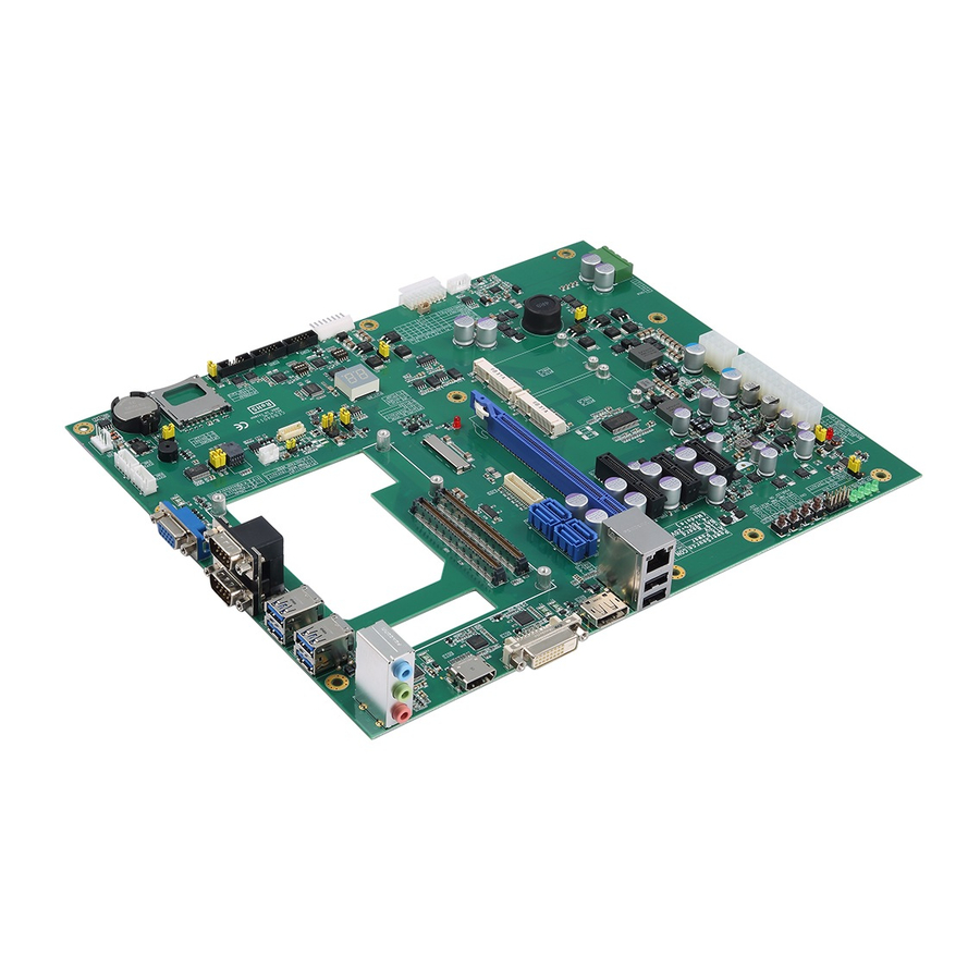
CEB94011 COM Express Type 6 Development Baseboard Chapter 2 Board and Pin Assignments Board Dimensions and Fixing Holes Top Side Board and Pin Assignments... - Page 12 CEB94011 COM Express Type 6 Development Baseboard Bottom Side Board and Pin Assignments...
-
Page 13: Board Layout
CEB94011 COM Express Type 6 Development Baseboard Board Layout Top Side Board and Pin Assignments... -
Page 14: Installing Cem Module And Heatsink
CEB94011 COM Express Type 6 Development Baseboard Installing CEM Module and Heatsink For thermal dissipation, a heatsink enables the components on the CEM module to dissipate heat efficiently. All heat generating components are thermally conducted to the heatsink in order to avoid hot spots. Below images illustrate how to install the heatsink. - Page 15 CEB94011 COM Express Type 6 Development Baseboard When installing the compact size CEM module on CEB94011, please add stand-off se the screws to secure the heatsink plate to the and secure with nut. Then, u CEM module. Note Board and Pin Assignments...
-
Page 16: Jumper Settings
And remove jumper clip from 2 jumper pins to open. Below illustration shows how to set up jumper. Properly configure jumper settings on the CEB94011 to meet your application purpose. Below you can find a summary table of all jumpers and onboard default settings. -
Page 17: Auto Power On (Jp1)
CEB94011 COM Express Type 6 Development Baseboard 2.4.1 Auto Power On (JP1) If JP1 is enabled for power input, the system will be automatically power on without pressing soft power button. If JP1 is disabled for power input, it is necessary to manually press soft power button to power on the system. -
Page 18: Restore Bios Optimal Defaults (Jp10)
CEB94011 COM Express Type 6 Development Baseboard 2.4.6 Restore BIOS Optimal Defaults (JP10) Put jumper clip to pin 2-3 for a few seconds then move it back to pin 1-2. Doing this procedure can restore BIOS optimal defaults. Function Setting... -
Page 19: Connectors
CEB94011 COM Express Type 6 Development Baseboard Connectors Signals go to other parts of the system through connectors. Loose or improper connection might cause problems, please make sure all connectors are properly and firmly connected. Here is a summary table which shows all connectors on the hardware. -
Page 20: Dvi-D Connector (Cn1)
CEB94011 COM Express Type 6 Development Baseboard 2.5.1 DVI-D Connector (CN1) DVI-D (Digital Video Interface – Digital only) provides transmission of fast and high quality digital video between source device and display device. Signal Signal DVI_DATA2- DVI_DATA2+ N.C. N.C. DVI_SPC DVI_SPD N.C. -
Page 21: Front Panel Connector (Cn3)
CEB94011 COM Express Type 6 Development Baseboard 2.5.3 Front Panel Connector (CN3) Signal Signal ATX_PSON- PWR LED PWR ON RESET HDD Activity LED- HDD Activity LED+ ATX Power Supply ON Pin 1 and Pin 2 connect to switch button. If switch button turn on, it means ATX power supply forcing to turn on state. -
Page 22: Displayport Connector (Cn4)
CEB94011 COM Express Type 6 Development Baseboard 2.5.4 DisplayPort Connector (CN4) The DisplayPort interface is available through connector CN4. Signal DDSP_TX_0_DP DDSP_TX_0_DN DDSP_TX_1_DP DDSP_TX_1_DN DDSP_TX_2_DP DDSP_TX_2_DN DDSP_TX_3_DP DDSP_TX_3_DN DP3_AUX_SEL DP3_AUX+ DP3_AUX- DP3_HPD +3.3V 2.5.5 Audio Jack (CN5) Install audio driver, then attach audio devices to CN5. -
Page 23: Ethernet And Usb 2.0 Port Stack (Cn6)
CEB94011 COM Express Type 6 Development Baseboard 2.5.6 Ethernet and USB 2.0 Port Stack (CN6) The board is equipped with high performance plug and play Ethernet interface fully compliant with the IEEE 802.3 standard. The Ethernet port uses RJ-45 connector. -
Page 24: Usb 3.0 Stacks (Cn7 And Cn8)
CEB94011 COM Express Type 6 Development Baseboard 2.5.7 USB 3.0 Stacks (CN7 and CN8) This Universal Serial Bus 3.0 (USB 3.0) connector on this board is for installing versatile USB interface peripherals. It is an 18-pin standard USB connector which is also compatible with USB 2.0 device. -
Page 25: Atx Power Connectors (Cn9 And Cn27)
CEB94011 COM Express Type 6 Development Baseboard 2.5.8 ATX Power Connectors (CN9 and CN27) Steady and sufficient power can be supplied to all components on the board by connecting power connector. Please make sure all components and devices are properly installed before connecting the power connector. -
Page 26: Com D-Sub Connector (Cn10)
CEB94011 COM Express Type 6 Development Baseboard 2.5.9 COM D-Sub Connector (CN10) The CN10 is a double-deck 9-pin D-Sub connector for RS-232 carrying only TXD and RXD signals from COM Express module. COM3 Signal Receive Data (RXD) Transmit Data (TXD) -
Page 27: Vga Connector (Cn12)
CEB94011 COM Express Type 6 Development Baseboard 2.5.11 VGA Connector (CN12) The CN12 is a standard 15-pin D-Sub connector which is commonly used for VGA monitor. This VGA interface configuration can be configured via software utility. Signal Signal Green Blue... -
Page 28: Sata Power Connectors (Cn16 And Cn17)
CEB94011 COM Express Type 6 Development Baseboard 2.5.14 SATA Power Connectors (CN16 and CN17) These two connectors are for SATA (Serial ATA) power input. Signal +12V 2.5.15 Wide Range Power Input Connectors (CN18) The wide range power input supports 5V to 20V. -
Page 29: Com1 And Com2 Connectors (Cn20 And Cn21)
CEB94011 COM Express Type 6 Development Baseboard 2.5.17 COM1 and COM2 Connectors (CN20 and CN21) The board has two RS-232/422/485 ports for user development. CN20 (COM1) RS-232 RS-422 RS-485 CN21 (COM2) No use No use No use No use No use... -
Page 30: Smbus Connector (Cn23)
CEB94011 COM Express Type 6 Development Baseboard 2.5.19 SMBus Connector (CN23) The SMBus interface is available through CN23. The SMBus (System Management Bus) is a simple bus for the purpose of lightweight communication. Signal +3.3V SMB_CLK_S SMB_DATA_S SMB_ALERT Board and Pin Assignments... -
Page 31: Edp Connector (Edp1)
CEB94011 COM Express Type 6 Development Baseboard 2.5.20 eDP Connector (eDP1) The eDP interface is available through 40-pin connector (eDP1). The eDP is a design to replace internal digital LVDS links in computer monitor panels and TV panels. You can select LVDS or eDP function with JP6, see section 2.4.3. -
Page 32: Lvds Connector (Lvds1)
CEB94011 COM Express Type 6 Development Baseboard 2.5.21 LVDS Connector (LVDS1) This board has a 2x20-pin connector for LVDS LCD interface. It is strongly recommended to use the matching JST SHDR-40VS-B connector for LVDS interface. Pin 1~6 VCCM can be set to +3.3V, +5V or +12V by setting JP5 (see section 2.4.2). - Page 33 CEB94011 COM Express Type 6 Development Baseboard 24-bit single channel 18-bit dual channel Pin Signal Pin Signal Pin Signal Pin Signal VCCM VCCM VCCM VCCM VCCM VCCM VCCM VCCM VCCM VCCM VCCM VCCM 10 GND 10 GND 11 N.C 12 N.C 11 N.C...
-
Page 34: Cpu Fan Connector (Fan1)
CEB94011 COM Express Type 6 Development Baseboard 2.5.22 CPU Fan Connector (FAN1) Fan is needed for cooling down CPU temperature. The CPU fan interface is available through FAN1. Signal FAN_TACHIN 2.5.23 SATA Connectors (SATA1~SATA4) The Serial Advanced Technology Attachment (Serial ATA or SATA) connector is computer bus interface for connecting to devices such as hard disk drive. - Page 35 CEB94011 COM Express Type 6 Development Baseboard Signal Signal Signal Signal GND (FIXED) GND (FIXED) GND (FIXED) GND (FIXED) GBE0_MDI3- GBE0_ACT# GND (FIXED) GND (FIXED) GBE0_MDI3+ LPC_FRAME# USB_SSRX0- USB_SSTX0- GBE0_LINK100# LPC_AD0 USB_SSRX0+ USB_SSTX0+ GBE0_LINK1000# LPC_AD1 GND (FIXED) GND (FIXED) GBE0_MDI2-...
- Page 36 CEB94011 COM Express Type 6 Development Baseboard Signal Signal Signal Signal PCIE_TX4- PCIE_RX4- PEG_RX1- PEG_TX1- GPO2 TYPE1# TYPE2# PCIE_TX3+ PCIE_RX3+ PEG_RX2+ PEG_TX2+ PCIE_TX3- PCIE_RX3- PEG_RX2- PEG_TX2- GND (FIXED) GND (FIXED) GND (FIXED) GND (FIXED) PCIE_TX2+ PCIE_RX2+ PEG_RX3+ PEG_TX3+ PCIE_TX2- PCIE_RX2-...
-
Page 37: Push Buttons
CEB94011 COM Express Type 6 Development Baseboard Push Buttons The board has four push buttons, see table below. Push Button Description LID push button Sleep push button Power push button Reset push button LED Indicators The board has six LEDs and one dual 7-segment LED display. See table below for detailed information.
Need help?
Do you have a question about the CEB94011 and is the answer not in the manual?
Questions and answers