Advertisement
2015-Current Ford F-150 Black Handle with Camera
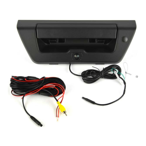
Kit Contents:
Tailgate Handle with Camera
Chassis Harness with RCA
1 bag containing:
Template (along with these instructions)
Before beginning, determine how the vehicle is equipped and check appropriate boxes:
Determine whether the vehicle has an opening in the center of pickup bed close to opposite of the opening in the
bottom of the tailgate.
□
YES, skip Section 1.
□
NO, tailgate must be removed to drill an opening for the camera harness (refer to Section 1).
□
Check kit contents are complete against the list above.
FLTW-7511
PRE-INSTALLATION VEHICLE CHECKLIST
Tools Required:
T30 Torx Driver
8mm and 10mm Sockets
Flat Head Screwdriver
Phillips Screwdriver
Plastic Trim Removal tool
Drill Bit (if needed)
1 inch Center Hole Saw
Soldering Iron
Small brush
Round file (if needed)
Deburring Tool
1 of 6
GS
Advertisement
Table of Contents

Related Manuals for BrandMotion FLTW-7511


Summary of Contents for BrandMotion FLTW-7511
-
Page 1: Installation Instructions
INSTALLATION INSTRUCTIONS FLTW-7511 2015-Current Ford F-150 Black Handle with Camera Kit Contents: Tools Required: Tailgate Handle with Camera T30 Torx Driver Chassis Harness with RCA 8mm and 10mm Sockets 1 bag containing: Flat Head Screwdriver Template (along with these instructions) - Page 2 INSTALLATION INSTRUCTIONS Pages Section 1: Cut Pickup Bed Opening (if required) Section 2: Camera Installation Section 3: Chassis Harness Installation Section 4: Wiring for Display Section 1: Cut Pickup Bed Opening Follow Steps 1 through 4 only if the vehicle does not have an opening in the bed above the license plate per Figure 1 Figure 1 Figure 3...
- Page 3 INSTALLATION INSTRUCTIONS Section 2: Camera Installation Remove the sheet metal cover from inside of the bed on the tailgate by removing the Torx bolts holding it on. Remove the tailgate handle by loosening two nuts with a 10mm socket. Route camera harness through handle opening in tailgate to the hole in the bottom of the tailgate. Reconnect to latch rods onto the handle.
- Page 4 INSTALLATION INSTRUCTIONS Section 3: Chassis Harness Installation 13. Remove the driver side sill plate with a trim 18. Clean the hole with a deburring tool. tool. Figure 8 Figure 5 14. Loosen driver side A-pillar molding using your hands, and then remove the driver side 19.
- Page 5 INSTALLATION INSTRUCTIONS Section 3: Chassis Harness Installation continued 21. Route the exterior portion of the supplied 22. Loop any excess from the harness as shown chassis harness along existing vehicle and secure with zip-ties. chassis harness and over fuel tank. Use zip- ties to secure the harness to existing wiring Figure 13 at 2-inch intervals.
- Page 6 INSTALLATION INSTRUCTIONS Section 4: Wiring for Display 24. If needed, install aftermarket display or navigation display per instructions. 25. Remove the door sillplate with a trim tool and remove passenger side kick panel with hands. 26. Attach an eyelet to the BLACK ground wire from the supplied chassis harness and connect it to the chassis ground or to sheet metal.
Need help?
Do you have a question about the FLTW-7511 and is the answer not in the manual?
Questions and answers