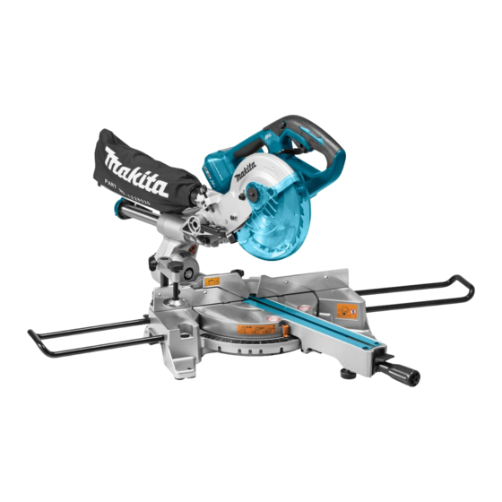
Makita DLS714 Instruction Manual
Cordless slide compound
miter saw
Hide thumbs
Also See for DLS714:
- Instruction manual (188 pages) ,
- Technical information (47 pages) ,
- Instruction manual (124 pages)
Table of Contents
Advertisement
Quick Links
Advertisement
Table of Contents

Related Manuals for Makita DLS714


Summary of Contents for Makita DLS714
- Page 1 INSTRUCTION MANUAL Cordless Slide Compound Miter Saw DLS714 Read before use.
-
Page 2: Specifications
SPECIFICATIONS Model: DLS714 Blade diameter 190 mm Blade body thickness 1.3 mm - 2.0 mm 20 mm or 15.88 mm Max. miter angle Left 47°, Right 57° Max. bevel angle Left 45°, Right 5° No load speed 5,700 min Dimensions (L x W x H) -
Page 3: Ec Declaration Of Conformity
If operating a power tool in a damp location is unavoid- able, use a residual current device (RCD) protected For European countries only supply. Makita declares that the following Machine(s): Personal Safety Stay alert, watch what you are doing and use common sense when operating a power tool. - Page 4 Do not use the power tool if the switch does not turn Wear eye protection. it on and off. Wear hearing protection to reduce the risk of with the switch is dangerous and must be repaired. hearing loss. Disconnect the plug from the power source and/or Wear gloves for handling saw blade (saw the battery pack from the power tool before making blades shall be carried in a holder wherever...
- Page 5 CAUTION: Only use genuine Makita batteries. 44. To reduce the emitted noise, always be sure of non-genuine Makita batteries, or batteries that have been that the blade is sharp and clean. 45. The operator is adequately trained in the use, adjustment and operation of the machine.
-
Page 6: Parts Description
PARTS DESCRIPTION Lock-off button Blade case lower limit position) Dust bag Bevel scale mum cutting capacity) Blade guard Vertical vice Guide fence Holder Lock lever (for turn base) Grip (for turn base) base) Turn base Thumb screw (for lock- Hex wrench Clamp screw (for locking ing upper slide pole) holder) -
Page 7: Installation
Installing or removing battery INSTALLATION cartridge Bench mounting CAUTION: Always switch off the tool before installing or removing of the battery cartridge. WARNING: Ensure that the tool does not CAUTION: Hold the tool and the battery car- move on the supporting surface. Movement of the miter saw on the supporting surface while cutting may cartridge. -
Page 8: Overheat Protection
Overheat protection Indicating the remaining battery capacity Blinking Only for battery cartridges with the indicator When the tool is overheated, the tool stops automati- cally, and the battery indicator blink about 60 seconds. In this situation, let the tool cool down before turning the tool on again. -
Page 9: Blade Guard
For tools with blade guard release lever Mode indicator status Operation mode High speed mode High torque mode This tool has "high speed mode" and "high torque mode". It automatically changes operation mode depending on the work load. When mode indicator lights up during operation, the tool is in high torque mode. - Page 10 WARNING: Do not remove spring holding blade guard. light exposure, contact a Makita service center for replace- ment. DO NOT DEFEAT OR REMOVE GUARD. Positioning kerf board This tool is provided with the kerf boards in the turn base to minimize tearing on the exit side of a cut.
- Page 11 2. Guide fence Stopper arm the saw blade comes slightly below the cross section of the guide fence and the top surface of the turn base. ing screw and press down the handle fully to check the result. Sub-fence CAUTION: When performing left bevel cuts, Rotate the blade by hand while holding the handle all Otherwise, it may con-...
- Page 12 Adjusting the miter angle 2. Bevel scale 3. To tilt the blade to the right, hold the handle and tilt the 1. Turn base 2. 3. Miter scale 4. Lock lever carriage to the left slightly, and push the release button. 5.
-
Page 13: Switch Action
3. Lock-off button 4. Hole for padlock For tools without blade guard release lever CAUTION: Use only the Makita hex wrench To prevent the switch trigger from being accidentally pulled, a lock-off provided to install or remove the blade. button is provided. To start the tool, press in the lock-off button and pull the switch trigger. - Page 14 To remove the blade, perform the following steps: Lock the handle in the raised position by pushing in the stopper pin. 4. Hex socket bolt (left-handed) 5. 6. Blade mount- ing part To install the blade, perform the following steps: Make sure that the direction of the arrow on the blade holding the center cover by turning it counterclockwise.
- Page 15 For tool without the ring 4. Hex socket bolt (left-handed) 5. 6. Blade mount- 4. Hex ing part socket bolt (left-handed) 5. CAUTION: Make sure that the blade mounting For tool with the ring Mounting the blade on the wrong side can result in the dangerous vibration.
-
Page 16: Securing Workpiece
Securing workpiece shape of the workpiece and secure the vise arm by tightening the upper screw. If the upper screw contacts WARNING: the guide fence, install the upper screw on the opposite It is extremely important to always side of vise arm. Make sure that no part of the tool secure the workpiece correctly with the proper contacts the vise when lowering the handle fully and type of vise. -
Page 17: Operation
means of supporting workpieces horizontally. NOTICE: Before use, be sure to release the Install them on the side of the tool, then tighten the handle from the lowered position by pulling the stopper pin. NOTICE: Do not apply excessive pressure on the handle when cutting. -
Page 18: Bevel Cut
Slide (push) cutting (cutting wide Bevel cut workpieces) WARNING: After setting the blade for a bevel cut, before operating the tool ensure that the car- WARNING: Whenever performing a slide cut, riage and blade will have free travel throughout the entire range of the intended cut. Interruption of the handle all the way down, then push the car- the carriage or blade travel during the cutting oper- riage toward the guide fence. -
Page 19: Compound Cutting
Compound cutting Compound cutting is the process in which a bevel angle is made at the same time in which a miter angle is being cut on a workpiece. Compound cutting can be performed at the angle shown in the table. Miter angle Bevel angle Left and Right 45°... - Page 20 Table (A) CAUTION: Never attempt to cut thick or round – Molding Bevel angle Miter angle aluminum extrusions. Thick aluminum extrusions may position come loose during operation and round aluminum extru- 52/38° 45° type 52/38° 45° type in the type type Left Left 30°...
-
Page 21: Carrying Tool
Carrying tool WARNING: Stopper pin is only for carrying and storage purposes and should never be used for any cutting operations. The use of the stopper pin for cutting operations may cause unexpected movement of the saw blade resulting in kickback and CAUTION: Always secure all moving portions before carrying the tool. -
Page 22: Adjusting The Cutting Angle
Adjusting the cutting angle but rough handling may have affected the alignment. If your tool is not aligned properly, perform the following: Miter angle tighten two clamp screws to secure the carriage. Rotate the turn base until the pointer indicates 0° on the miter scale. -
Page 23: After Use
ACCESSORIES so that it indicates 0°. WARNING: These Makita accessories or attach- ments are recommended for use with your Makita tool The use of any other accesso- WARNING: Only use the Makita accessory or attachment for its stated purpose. Misuse of an acces- If you need any assistance for more details regarding these 1. - Page 24 Jan-Baptist Vinkstraat 2, Makita Europe N.V. 3070 Kortenberg, Belgium 3-11-8, Sumiyoshi-cho, Makita Corporation Anjo, Aichi 446-8502 Japan 885417B222 www.makita.com 20160523...
Need help?
Do you have a question about the DLS714 and is the answer not in the manual?
Questions and answers