Deif GC-1F Operator's Manual
Gen-set controller
Hide thumbs
Also See for GC-1F:
- Operator's manual (9 pages) ,
- Installation instructions manual (123 pages)

Related Manuals for Deif GC-1F


Summary of Contents for Deif GC-1F
- Page 1 OPERATOR’S MANUAL Gen-set Controller, GC-1F • Push-buttons • LEDs • Icon list • Display readings Document no.: 4189340475C...
- Page 2 GC-1F Operator’s Manual This description includes the following versions: GC-1F SW version 1.2x.x GC-1F/2 SW version 2.0x.x or later DEIF A/S Page 2 of 11...
-
Page 3: Table Of Contents
GC-1F Operator’s Manual Table of contents ABOUT THIS DOCUMENT ....................4 ........................4 ENERAL PURPOSE .......................... 4 NTENDED USERS ....................4 ONTENTS OVERALL STRUCTURE WARNINGS AND LEGAL INFORMATION ................5 ..................5 EGAL INFORMATION AND RESPONSIBILITY ..................5 LECTROSTATIC DISCHARGE AWARENESS .......................... -
Page 4: About This Document
1. About this document General purpose This document is the Operator’s Manual for DEIF’s generator controller GC-1F. The document includes information about push-buttons, LEDs, display readings and icon list. The general purpose is to give the operator important information to be used in the daily operation of the unit. -
Page 5: Warnings And Legal Information
2. Warnings and legal information Legal information and responsibility DEIF takes no responsibility for installation or operation of the engine set. If there is any doubt about how to install or operate the engine controlled by the unit, the company responsible for the installation or the operation of the set must be contacted. -
Page 6: Ul Applications
GC-1F Operator’s Manual UL applications These flat surface panel-mounted controllers are intended to be used in Listed Generator Assemblies where the suitability of the combination has been determined by Underwriters Laboratories. These devices have been evaluated for fire and shock only. The accuracy and/or reliability of the voltage regulating function has not been evaluated. -
Page 7: Push-Buttons, Leds And Display
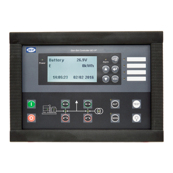
GC-1F Operator’s Manual 3. Push-buttons, LEDs and display Unit 160 x 220 mm (6.30” x 8.66”) Front dimensions H x W 54 mm (2.13 “) Unit depth Push-button functions The push-buttons on the unit have the following functions: ▲: Start engine (local (not auto)) running mode. - Page 8 GC-1F Operator’s Manual Start engine (local (not auto)) running mode. Stops the engine instantaneously. If the unit is in AUTO mode, the mode will change to MAN and the engine will stop. AUTO running mode selector. AUT: Manual running mode selector.
- Page 9 GC-1F Operator’s Manual Power OK indicator. Power: Flashing: Active, non-acknowledged alarm(s) present. Alarm: Steady: Active, acknowledged alarm(s) present. Additional alarm Flashing: Active, non-acknowledged alarm(s) where output A or B is indication LEDs: configured to LED 1, 2, 3 or 4.
- Page 10 GC-1F Operator’s Manual Display functions The display indicates both readings and alarms. Illustrated below are examples with icons and English language. GC-1F Type, Hardware and software version. HW x.xx SW x.xx Fuel level 80 % Oil press 2.0 bar Fuel level, Oil pressure, water temp. and RPM.
- Page 11 Operator’s Manual The available parameters depend on the set options. Some parameters can only be changed using the PC utility software (USW) for GC-1F. The parameter list will automatically be abandoned, if no button is pressed during a 30 sec. period.
Need help?
Do you have a question about the GC-1F and is the answer not in the manual?
Questions and answers