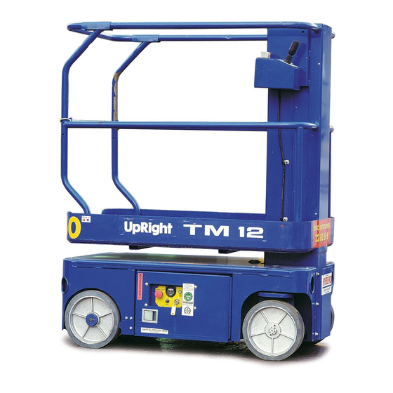
Upright TM12 Service Manual
Work platform.
serial numbers 7352 - current
Hide thumbs
Also See for TM12:
- Service & parts manual (102 pages) ,
- Operator's manual (26 pages) ,
- Service and parts manual (146 pages)
Table of Contents
Advertisement
Quick Links
Advertisement
Chapters
Table of Contents
Troubleshooting

Related Manuals for Upright TM12


Summary of Contents for Upright TM12
- Page 1 TM12 Work Platform Serial Numbers 7352 - Current Publication Number: 107099-002...
- Page 2 Serial Number 7352 to current When contacting UpRight for service or parts information, be sure to include the MODEL and SERIAL NUMBERS from the equipment nameplate. Should the nameplate be missing, the SERIAL NUMBER is also stamped on top of the chassis near the front axle pivot.
- Page 3 This manual consists of five (5) parts. P E R A T O R A N U A L A copy of the Operator Manual that is stored on every UpRight Aerial Work Platform. 1 - G E C T I O N...
- Page 4 Foreword OTES Page ii Service Manual...
- Page 5 • LOOK up, down and around for overhead obstructions and electrical conductors. • DISTRIBUTE all platform loads evenly on the platform. • NEVER use damaged equipment. (Contact UpRight for instructions. See toll free phone number on inside back cover.) • NEVER change operating or safety systems.
-
Page 6: Table Of Contents
Specifications ...............16 Page 2 107098-002 TM12 - Operator Manual... -
Page 7: Introduction
Introduction NTRODUCTION This manual covers the TM12 Aerial Work Platform. This manual must be stored on the machine at all times. Read, understand and follow all safety rules and operating instructions before attempting to operate the machine. ENERAL ESCRIPTION Figure 1: TM12 Series... -
Page 8: Controls And Indicators
6. Check that all guardrails are properly in place and secured with all fasteners properly torqued. 7. Inspect the machine thoroughly for cracked welds, loose or missing hardware, hydraulic leaks, dam- aged cables or hoses, loose wire connections, and wheel bolts. Page 4 107098-002 TM12 - Operator Manual... -
Page 9: System Function Inspection
17. Push the Platform Emergency Stop Switch in to the OFF position. All machine functions should be dis- abled. Pull the Platform Emergency Stop Switch out to resume. 107098-002 TM12 - Operator Manual Page 5... -
Page 10: Operation
O W E R I N G L A T F O R M 1. Position the Lift/Drive Switch to LIFT. 2. While depressing the Interlock Switch, pull back on the Control Handle. Page 6 107098-002 TM12 - Operator Manual... -
Page 11: Emergency Lowering
2. Park the machine on a firm level surface, preferably under cover, secure against vandals, children and unauthorized operation. 3. Turn the Chassis Key Switch to OFF and remove the key to prevent unauthorized operation. 107098-002 TM12 - Operator Manual Page 7... -
Page 12: Transporting The Machine
C A U T I O N Overtightening chains or straps attached to the Tie Down lugs may result in damage to the machine Forklift From Side Typical Tie Down/Lift Points (D-Rings) Page 8 107098-002 TM12 - Operator Manual... -
Page 13: Maintenance
3. Remove the filler cap from the hydraulic fluid reser- voir. 4. Check the fluid level on the dipstick on the filler cap. 5. Add the appropriate fluid to bring the level to the FULL mark. See “Specifications” on page 16. 107098-002 TM12 - Operator Manual Page 9... -
Page 14: Battery Maintenance
Battery fluid is highly corrosive. Thoroughly rinse away any spilled fluid with clean water. Always replace batteries with UpRight batteries or manufacturer approved replacements weighing 26,3 kg (58 lbs.) each. • Check the battery fluid level daily, especially if the machine is being used in a warm, dry climate. -
Page 15: Battery Charging
NOTE: The battery charger circuit must be used with a GFI (Ground Fault Interrupt) outlet. NOTE: DO NOT operate the machine while the charger is plugged in. 107098-002 TM12 - Operator Manual Page 11... -
Page 16: Daily Inspection And Maintenance Schedule
Always block the elevating assembly whenever it is necessary to perform maintenance while the platform is elevated. The daily preventative maintenance checklist has been designed for machine service and maintenance. Please photocopy the Daily Preventative Maintenance Checklist and use the checklist when inspecting the machine. Page 12 107098-002 TM12 - Operator Manual... -
Page 17: Daily Preventative Maintenance Checklist
Inspect for external damage, dents, loose rivets Check entry way closure. Elevating Assembly or cracks. Tires Check for damage. Emergency Hydraulic Operate the emergency down valve and check Wheels Check for loose components System for serviceability. 107098-002 TM12 - Operator Manual Page 13... -
Page 18: Labels
Secure gate or chain across enterance. DO NOT use ladders or scaffolding on platform DO NOT climb down mast. 066550-001 DOWN 066556-001 REVERSE UpRight LIFT DRIVE 014222-003-99 CUTOUT CUTOUT 107051-000 EMERGENCY STOP 061220-002 8 107050-000 Page 14 107098-002 TM12 - Operator Manual... - Page 19 Labels Figure 11: Safety Labels Locations 107098-002 TM12 - Operator Manual Page 15...
-
Page 20: Specifications
*Specifications are subject to change without notice. Hot weather or heavy use may affect performance. Refer to the Parts Manual and the Service Manual for complete parts and service information. The TM12 meets or exceeds all applicable requirements of OSHA and ANSI A92.6-1999. Page 16... - Page 21 Table 1-5: Specific Gravity and Battery Voltage ......... 1-13 Table 1-6: Battery Charging, UpRight Electric and BiEnergy Machines ..... . . 1-14 Table 1-7: Battery Charger Troubleshooting .
-
Page 22: Hazard Indicators
UpRight, Inc., might be done, or of the possible hazardous consequences of each conceivable way, nor could UpRight Inc. investigate all such ways. Anyone using service procedures or tools, whether or not recommended by UpRight Inc., must satisfy themselves thoroughly that neither personal safety nor... -
Page 23: Torque Specifications
O M P O N E N T S NOTE: Always lubricate threads with clean hydraulic fluid prior to installation Use the following values to torque hydraulic components used on UpRight Aerial Work Platforms. Table 1-1: Torque Specifications for Hydraulic Components... -
Page 24: Table 1-3: Torque Specifications For Metric Fasteners, U.s. Customary Units
Torque Specifications Section 1 - General Information Table 1-3: Torque Specifications for Metric Fasteners, U.S. Customary Units 12.9 10.9 Grade 12.9 Grade 10.9 Grade 8.8 Nominal Tightening Torque Tightening Torque Tightening Torque Clamp Clamp Clamp Thread Load Load Load K =,15 K =,20 K =,15 K =,20... -
Page 25: Date Code Identification On Hoses
• Optimizer with adapter (UpRight P/N 100329-000) • Flow Meter Kit (UpRight P/N 067040-000) • Quadragauge with fitting (UpRight P/N 063971-000) • 0-25 kg (0-50 Lbs.) Chain Tension Scale (UpRight P/N 107078-000) IGHT • Gland Nut Wrench (UpRight P/N 062521-000) •... -
Page 26: Upright Connectors
UpRight Connectors Section 1 - General Information 1-6 U IGHT ONNECTORS UpRight connectors are designed so that connector parts, contacts or electrical cables may be replaced without replacing the entire connector. Figure 1-1: UpRight Connector Kits Small Kit Large Kit... -
Page 27: Figure 1-4: Locking Finger, Upright Connector
E L E A S I N G O C K I N G I N G E R S Figure 1-4: Locking Finger, UpRight Connector 1. The Locking Fingers can be released following the removal of the Locking Wedge of either the male or female connector. -
Page 28: Hydraulic Manifold Repair
Hydraulic Manifold Repair Section 1 - General Information 1-7 H YDRAULIC ANIFOLD EPAIR E M O V A L Refer to the Service and Repair section for model specific information. 1. Disconnect the battery. 2. Tag and disconnect the solenoid valve leads. 3. -
Page 29: Cylinder Repair
Section 1 - General Information Cylinder Repair 1-8 C YLINDER EPAIR W A R N I N G Cylinders may be very heavy. Support heavy cylinders before removing pins which secure the cylinder to the machine. E M O V A L NOTE: Refer to the Service and Repair section for the location of cylinders, and the Parts Manual for a list of parts which secure the cylinders. -
Page 30: Electric Motors
Electric Motors Section 1 - General Information 1-9 E LECTRIC OTORS R O U B L E S H O O T I N G Figure 1-6: Electric Motor Service 1. Read the nameplate to become familiar with Ammeter the motor, especially the rated voltage. Power 2. -
Page 31: Figure 1-7: Electric Motor Brushes
Section 1 - General Information Electric Motors N S P E C T I O N Once the motor has been disassembled, go through the following check-list steps to determine where the problem lies. 1. Bearings should spin smoothly and easily and have ample lubrication and be free of corrosion. 2. -
Page 32: Battery Maintenance
Battery fluid is highly corrosive. Thoroughly rinse away any spilled fluid with clean water. Always replace batteries with UpRight batteries or manufacturer approved replacements. Before disconnecting the battery negative (-) lead, make sure all switches are OFF. If ON, a spark will occur at the ground terminal which could cause an explosion if hydrogen gas or fuel vapors are present. -
Page 33: Table 1-5: Specific Gravity And Battery Voltage
A T T E R Y H E C K Electric UpRight Aerial Work Platforms use deep cycle batteries. If poor service life is experienced, batter- ies should be checked for bad cells. Fully charge batteries for 14 hours minimum, ensuring that the charger has completed its cycle (see ‘Battery Charging”... -
Page 34: Table 1-6: Battery Charging, Upright Electric And Bienergy Machines
4. Connect the other end of the extension cord to a grounded AC outlet of proper current, voltage and fre- quency rating. 5. The charger turns on automatically after a short delay. Table 1-6 illustrates charging indicators. Table 1-6: Battery Charging, UpRight Electric and BiEnergy Machines Charger Display AC Charging Current... -
Page 35: Table 1-7: Battery Charger Troubleshooting
If the problem is not resolved after going through the entire table, the charger should be replaced. NOTE: The majority of chargers returned to UpRight as “failed” test good. Please follow the troubleshooting procedures carefully. Table 1-7: Battery Charger Troubleshooting... -
Page 36: Floor Loading
Localized Pressure or Occupied Pressure. To calculate Floor Loading, find the Total Weight of the machine. TOTAL WEIGHT = MACHINE WEIGHT + MAXIMUM PLATFORM CAPACITY. Refer to the machine specifications or contact UpRight or your UpRight dealer. O C A L I Z E D R E S S U R E ²... -
Page 37: Hydraulic Fluid
Unless recommended by UpRight, do not mix hydraulic fluids of different brands or types. The required additives and fluid viscosities may vary. If the use of hydraulic fluids other than listed below is desired please contact UpRight Product Support. OBILFLUID •... -
Page 38: Long Term Storage
Long Term Storage Section 1 - General Information 1-13 L TORAGE NOTE: Do not drain the hydraulic system prior to long term storage. If the machine is to be placed in long term storage, follow these recommended preservation procedures. R E S E R V A T I O N 1. -
Page 39: Able Of Ontents
This section contains instructions for the maintenance of the machine. Refer to the General Information section for information relevant to all UpRight Aerial Work Platforms. Referring to the Operator Manual will aid in understanding the operation and function of the various components and systems of the machine, and help in diagnosing and repair of the machine. -
Page 40: Ist Of
Figure 2-21: Chassis Controls..............2-26 Page 2-2 107099-002 TM12 Work Platform... -
Page 41: Supporting Elevating Assembly
2. Remove the block. 3. Move the Chassis Lift Switch to the DOWN position and completely lower the work platform 1 Wood Block 50 cm (18 in.) long 2. Number Two Mast 3. Number One Mast 107099-002 TM12 Work Platform Page 2-3... -
Page 42: Preventative Maintenance
The preventative maintenance table has been designed for machine service and maintenance repair. Please photocopy the following page and use the table as a checklist when inspecting the machine for service. Page 2-4 107099-002 TM12 Work Platform... -
Page 43: Preventative Maintenance Check List
Check steering cylinder for leaks Rails Check condition of deck Daily Check hardware & fittings for proper torque Check entry way closure Daily NOTE: Use ISO #46 during summer and ISO #32 during winter. 107099-002 TM12 Work Platform Page 2-5... -
Page 44: Parts Location
Circuit Board Proximity Switch Relay Control Cable Assembly Flow Control Valve Assembly Electrical Box Assembly Hydraulic Hydraulic Oil Reservoir Filter Assembly Tilt Sensor Assembly Batteries 6 Volt Power Unit Battery Charger Control Valve Assembly Page 2-6 107099-002 TM12 Work Platform... -
Page 45: General Lubrication
Figure 2-3: Lubrication Points • Apply grease to each grease fitting. G Grease # Oil • Apply one or two drops of motor oil to each bearing. 1. King Pin Bearings 2. Steering Linkage 3. Wheel Bearings 107099-002 TM12 Work Platform Page 2-7... -
Page 46: Batteries
State of California to cause cancer and reproductive harm. Wash hands after handling. Battery fluid is highly corrosive. Thoroughly rinse away any spilled fluid with clean water. Always replace batteries with UpRight batteries or manufacturer approved replacements weighing 26,3 kg (58 lbs.) each. -
Page 47: Hydraulics
7,2 l (1.9 US gal.). C A U T I O N The hydraulic fluid may be of sufficient temperature to cause burns. Wear safety gloves and protective eye wear when handling hot fluid. 107099-002 TM12 Work Platform Page 2-9... -
Page 48: Hydraulic Pump
1. Valve Block 3. Fitting, 6MB - 6MJ 2. Flow Control Valve ° 4. Fitting, 6MB - 4MJ x 90 3,8 lpm (1 gpm) ° 5. Fitting, 6MB - 6MJ x 90 Emergency Down Valve Page 2-10 107099-002 TM12 Work Platform... -
Page 49: Main Hydraulic Manifold
11. Lift Valve 23. Drive RV Forward/Reverse 2-Position - 4-Way Solenoid Valve with Coil 3-Position - 4-Way Solenoid 12. Coil with Coils 13. Steering Valve 24. Fitting, Plug #4 3-Position - 4-Way Solenoid with Coils 107099-002 TM12 Work Platform Page 2-11... -
Page 50: Setting Hydraulic Manifold Pressures
Lift Valve Steering Relief Valve the lift relief valve, and torque to 8 N-m (6 ft. Gage Port Check Valve lbs.). Depression Valve Flow Divider Valve 8. Lower the platform. Forward/Reverse Valve Main Relief Valve Page 2-12 107099-002 TM12 Work Platform... - Page 51 69 bar (1000 psi). 5. Tighten the locknut or replace the steering relief valve cover and torque to 8 N-m (6 ft. lbs.). 6. Remove the gauge and replace the cap. 107099-002 TM12 Work Platform Page 2-13...
-
Page 52: Cylinders
5. Remove the cylinder. 1. Depression Cylinder 3. Cotter Pin 2. Pivot Pin 4. Depression Guard EPAIR Refer to Cylinder Repair in Section 1 - General Information. NSTALLATION Installation is reverse of removal. Page 2-14 107099-002 TM12 Work Platform... -
Page 53: Brake Cylinder
6. Lower the machine and operate the drive circuit and check that the brake bars retract and clear the tires when driving and fully engage the tires when stopped. Check for leaks 107099-002 TM12 Work Platform Page 2-15... -
Page 54: Steering Cylinder
3. Head Cap 4. Piston 5. Piston Nut Seal Kit Includes: A. O-Ring B. Backup Ring C. Rod Wiper D. U-Cup E. Teflon Piston Ring F. O-Ring (under Piston Ring) G. Backup Ring (2) H. O-Ring Page 2-16 107099-002 TM12 Work Platform... -
Page 55: Lift Cylinder
6. Remove the plug from the hydraulic hose and attach it to the adapter. 7. Attach the vent line to the hydraulic tank. 8. Test with weight at rated platform load to check system operation. Check for leaks 107099-002 TM12 Work Platform Page 2-17... -
Page 56: Drive Motors
DO NOT back-off the nut to install 7. Thrust Bushing the cotter pin. 8. Thrust Washer 6. Remove the blocks, lower and remove the jack. 7. Operate the drive system and check for leaks. Page 2-18 107099-002 TM12 Work Platform... -
Page 57: Elevating Assembly
8 Chain Inspection Cover 19 Adapter 9 Inner Chain Anchor 20 Retaining Ring 10a Outer Chain Anchor 21 Proximity Switch 10b Outer Chain/Inner Pulley 22 Emergency Lowering Knob Mount 23 Chassis 11 Rear Mast Bearing 107099-002 TM12 Work Platform Page 2-19... -
Page 58: Lift Chain Lubrication
IMPORTANT: There are two pairs of two chains each, for a total of four chains. If only one chain of either pair is damaged, both chains in the pair must be replaced. Page 2-20 107099-002 TM12 Work Platform... -
Page 59: Chain Tension Inspection
If the chains have elongated beyond the indicated range, replace the lift chain sets. Before reinstalling the lift chains, take this opportunity to thoroughly clean and lubricate the entire chain. Reassemble the elevat- ing assembly as described below. 107099-002 TM12 Work Platform Page 2-21... -
Page 60: Removal Of Elevating Assembly
12 N-m (107 in-lbs). • For all of the screws that attach the mast bearings, apply Locktite Retainer #405 to the screw threads. Do not torque, simply tighten securely. • Check elevating assembly for proper operation. Page 2-22 107099-002 TM12 Work Platform... -
Page 61: Sensors
2. Support the elevating assembly (see “Sup- Adjusting Screws porting Elevating Assembly” on page 2-3). (only one visible) 3. Push the level sensor to the side. The red LED should turn on, and the tilt alarm should sound. 107099-002 TM12 Work Platform Page 2-23... -
Page 62: Proximity Switch
2. Tighten the inner adjustment nut securely. 3. Connect the switch leads. 4. Install the chassis top cover. 5. Remove the elevating assembly support and fully lower the work platform. Page 2-24 107099-002 TM12 Work Platform... -
Page 63: Controls
Rocker, Steering Left Handle Half Switch, Steering Switch, Interlock Right Handle Half Emergency Stop Switch Lever, Interlock Lift/Drive Boot, Handle Selector Switch Emergency Lift/Drive Stop Selector Hall Effect Device Switch Switch 12 Pin Connector 107099-002 TM12 Work Platform Page 2-25... -
Page 64: Chassis Controls
4. Up/Down Toggle Switch Indicator 4b. Boot Switch Cover 2. Mushroom Emergency Stop 5. Circuit Breaker Switch 6. Alarm, Dual Tone 2b. E-Stop Switch Contact 7. Connector Cable, 3/4” 3. Key Chassis/Platform 8. Box Weldment Selector Switch Page 2-26 107099-002 TM12 Work Platform... - Page 65 3-10 Hydraulic ..............2-12 107099-002 TM12 Work Platform...
-
Page 66: Ist Of Ables
Table 3-8: Hydraulic Troubleshooting Table ............2-12 Page 3-2 107099-002 TM12 Work Platform... -
Page 67: Technical Support
Use the charts on the following pages to help determine the cause of a fault in your UpRight work platform NOTE: Spike protection diodes at components have been left out of the charts to eliminate confusion. -
Page 68: Motor Controller Dip Switch Settings
4 (fastest) ECELERATION Switches 5 & 6 determine the deceleration time. Switch 5 is for the deceleration rate while the platform is lowered. Switch 6 is for the elevated rate. DECEL 0.24 sec. 1.27 sec. Page 3-4 107099-002 TM12 Work Platform... -
Page 69: I/O Board Dip Switch Settings
Switches 3 & 4 work together to determine the optional alarm settings RESULT Two Speed Mode (not used) Proportional Control not used Depression Mechanism extends when platform is raised Down alarm only Down and Reverse alarm Drive and Down alarm All Motion alarm 107099-002 TM12 Work Platform Page 3-5... -
Page 70: Led Fault Codes
7 Flash Check batteries and cable connections. above 45V. connections Controller is overheated due to Allow system to cool. 8 Flash Thermal cut-off. overuse or other failure Locate and repair other source of overheat. Page 3-6 107099-002 TM12 Work Platform... -
Page 71: Leds At I/O Board
4. Perform all machine functions until the Red LED is ON. Determine which function activated the Red LED and check all components that are active for that function. Figure 3-5: I/O Board Grey Green LED Red LED Dip Switch Part Serial Black Green 107099-002 TM12 Work Platform Page 3-7... -
Page 72: I/O Board Inputs And Outputs
Control Handle is moved in either direction 0.2V Steer Left selected J1-11 Steer Left input from Steering switch — Steer Left not selected Steer Right selected J1-12 Steer Right input from Steering switch — Steer Right not selected Page 3-8 107099-002 TM12 Work Platform... - Page 73 — Down not requested Drive requested J3-6 Depression mechanism activation (retract) — Drive not requested J3-7 Not Used — — — J3-8 Battery negative supply for Tilt sensor and Proximity switch — B– J4-11 107099-002 TM12 Work Platform Page 3-9...
- Page 74 Direction enable — Forward/Reverse not requested 4.0V - 4.3V 4.3V Signal starts high and drops proportionally as J5-8 Speed signal to EMC motor controller dropping to — Control Handle is moved in either direction 0.2V Page 3-10 107099-002 TM12 Work Platform...
-
Page 75: Electric
PQ Control Handle--S8 Height Limit Switch--S9 Platform Steering Switch--S10 Tilt Sensor--SNSR Steering Solenoid (right)--SOL1A Steering Solenoid (left)--SOL1B Platform Lift Solenoid--SOL2A Down Solenoid--SOL2B Depression Mechanism Extension Solenoid--SOL3A Depression Mechanism Retraction Solenoid--SOL3B Reverse Solenoid--SOL4A Forward Solenoid--SOL4B 107099-002 TM12 Work Platform Page 3-11... - Page 76 Drive Motors (2)--MOT Pump--PMP Main Relief Valve--RV3 Steering Relief Valve--RV1 Lift Relief Valve--RV2 Orofice--OR Tank--TNK Steering Right/Left Valve--V1 Lift Valve--V2A Down/Emergency Lowering Valve--V2B Depression Mechanism Retract Valve--V3B Depression Mechanism Extend Valve--V3A Forward/Reverse Valve--V4 Counterbalance Valve--V5 Page 3-12 107099-002 TM12 Work Platform...
-
Page 77: Able Of Ontents
4-2 Hydraulic Schematic ..........4-4 107099-002 TM12 Work Platform... -
Page 78: Hydraulic
Battery Tray Depression Mechanism Hydraulic SOL6 Extends depression mechanism bars Extension Manifold Solenoid SOL7 Down Solenoid Lowers platform Lift Cylinder Depression Depression SOL8 & Mechanism Retracts depression mechanism bars Mechanism SOL9 Retraction cylinder Solenoid Page 4-2 107099-002 TM12 Work Platform... - Page 79 Section 4 - Schematics Electric Schematic 107099-002 TM12 Work Platform Page 4-3...
- Page 80 Provides oil control for DM bar Hydraulic Manifold Extend Valve Forward/Reverse Provides oil control for drive or Hydraulic Manifold Valve lift functions Counterbalance Prevents machine from running Hydraulic Manifold Valve away on slopes; cushions stops Page 4-4 107099-002 TM12 Work Platform...
- Page 81 Section 4 - Schematics Hydraulic Schematic 107099-002 TM12 Work Platform Page 4-5...
- Page 82 Section 4 - Schematics OTES Page 4-6 107099-002 TM12 Work Platform...
- Page 83 Call Toll Free in U.S.A. 1-800-926-LIFT...
- Page 84 UpRight, Inc. UpRight 801 South Pine Street Unit S1, Park West Industrial Park Madera, California 93637 Friel Avenue Call Toll Free in U.S.A. Nangor Road TEL: 559-662-3900 Dublin 12, Ireland 1-800-926-LIFT FAX: 559-673-6184 TEL: +353 1 620 9300 PARTS: 1-888-UR-PARTS...
Need help?
Do you have a question about the TM12 and is the answer not in the manual?
Questions and answers