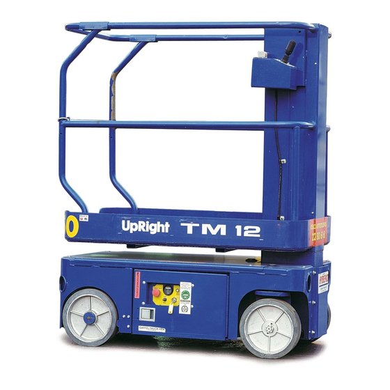
Upright TM 12 Series Service & Parts Manual
Work platforms
Hide thumbs
Also See for TM 12 Series:
- Service & parts manual (102 pages) ,
- Service manual (84 pages) ,
- Operator's manual (26 pages)
Table of Contents
Advertisement
Advertisement
Chapters
Table of Contents
Troubleshooting

Related Manuals for Upright TM 12 Series


Summary of Contents for Upright TM 12 Series
- Page 1 TM 12...
- Page 3 Serial Numbers 50000 – Current When contacting UpRight for service or parts information, be sure to include the MODEL and SERIAL NUMBERS from the equipment nameplate. Should the nameplate be missing, the SERIAL NUMBER is also stamped on top of the chassis above the front axle pivot.
- Page 5 TM12 SEVICE AND PARTS MANUAL PART NUMBER : 505115-000 SERIAL N . 50000 OREWORD OW TO ANUAL This manual is divided into six sections. NTRODUCTION ECTION General description and machine specifications. PERATION AND PECIFICATIONS ECTION Information on how to operate the work platform and how to prepare it for operation. AINTENANCE ECTION Preventative maintenance and service information.
- Page 6 Please understand that these warnings cannot cover all conceivable ways in which service, whether or not recommended by UpRight, might be done, or of the possible hazardous consequences of each conceivable way, nor could UpRight investigate all such ways.
- Page 7 NTRODUCTION URPOSE The purpose of this service and parts manual is to provide instructions and illustrations for the operation and maintenance of the TM12 manufactured by UpRight. COPE The manual includes procedures for proper operation, maintenance, adjustment, and repair of the TM12 as well as recommended maintenance schedules and troubleshooting.
- Page 8 Introduction 1.2 - General Description HASSIS The chassis is a structural frame that supports all the components of the TM12 work platform. The platform is raised and lowered using a scissors mechanism. Lift is achieved using a single stage cylinder. URPOSE OF QUIPMENT The objective of the work platform is to provide a quickly deployable, sel- propelled, variable...
- Page 9 NEVER charge batteries near sparks or open flame. Charging batteries emit explosive hydrogen gas. Modifications to the aerial work platform are prohibited or permissible only at the approval by UpRight. AFTER USE, secure the work platform from unauthorized use by turning the keyswitch off and removing key.
-
Page 10: Table Of Contents
ONTENTS Introduction ............... . . 3 General Description . -
Page 11: Introduction
Introduction NTRODUCTION This manual covers all models of the TM12 Aerial Work Platform. This manual must be stored on the machine at all times. Read, understand and follow all safety rules and operating instructions before attempting to operate the machine. ENERAL ESCRIPTION Figure 1: TM12 Series... -
Page 12: Special Limitations
Special Limitations PECIAL IMITATIONS Travel with the platform raised is limited to creep speed range. Elevating the platform is limited to firm, level surfaces only. D A N G E R The elevating function shall ONLY be used when the work platform is level and on a firm surface. The work platform is NOT intended to be driven over uneven, rough, or soft terrain. -
Page 13: Controls And Indicators
Controls and Indicators ONTROLS AND NDICATORS The operator shall know the location of each control and indicator and have a thorough knowledge of the function and operation of each before attempting to operate the unit. Figure 2: Controls and Indicators Platform Controller Chassis Controller (Right Side) Side View... -
Page 14: System Function Inspection
System Function Inspection YSTEM UNCTION NSPECTION Refer to Figure 1 and Figur e2 for the locations of various controls and indicators. W A R N I N G STAND CLEAR of the work platform while performing the following checks. Before operating the machine, survey the work area for surface hazards such as holes, drop-offs, bumps and debris. -
Page 15: Operation
Operation PERATION Before operating the machine, ensure that the Pre-Operation Safety Inspection has been completed and that any deficiencies have been corrected. Never operate a damaged or malfunctioning machine. The operator must be thoroughly trained on this machine. R A V E L I T H L A T F O R M O W E R E D... -
Page 16: Emergency Lowering
Operation M E R G E N C Y O W E R I N G W A R N I N G If the platform should fail to lower, NEVER climb down the elevating assembly. Stand clear of the elevating assembly while operating the Emergency Lowering Valve Knob. Figure 4: Emergency Lowering Valve Ask a person on the ground to open the Emergency Lowering Valve to lower the platform. -
Page 17: Transporting The Machine
Transporting the Machine RANSPORTING THE ACHINE R A N E Secure the straps to chassis lifting/tie down points only. O R K L I F T D A N G E R Forklifting is for transport only. See specifications for weight of machine and be certain that forklift is of adequate capacity to lift the machine. -
Page 18: Maintenance
Maintenance AINTENANCE W A R N I N G Never perform service while the platform is elevated without first blocking the elevating assembly. DO NOT stand in the elevating assembly area while deploying or storing the brace. Figure 7: Supporting the Elevating Assembly L O C K I N G T H E L E V A T I N G S S E M B L Y... -
Page 19: Battery Maintenance
Always wear safety glasses when working near batteries. Battery fluid is highly corrosive. Thoroughly rinse away any spilled fluid with clean water. Always replace batteries with UpRight batteries or manufacturer approved replacements weighing 26,3 kg (58 lbs.) each. • Check the battery fluid level daily, especially if the machine is being used in a warm, dry climate. -
Page 20: Inspection And Maintenance Schedule
Inspection and Maintenance Schedule NSPECTION AND AINTENANCE CHEDULE The Complete Inspection consists of periodic visual and operational checks, along with periodic minor adjustments that assure proper performance. Daily inspection will prevent abnormal wear and prolong the life of all systems. The inspection and maintenance schedule should be performed at the specified inter- vals. -
Page 21: Daily Preventative Maintenance Checklist
Daily Preventative Maintenance Checklist AILY REVENTATIVE AINTENANCE HECKLIST AINTENANCE ABLE REVENTATIVE AINTENANCE EPORT Y = Yes/Acceptable Date: _______________________________________ N = No/Not Acceptable Owner: ______________________________________ R = Repaired/Acceptable Model No: ___________________________________ Serial No:____________________________________ Serviced By: _________________________________ COMPONENT INSPECTION OR SERVICES COMPONENT INSPECTION OR SERVICES Check electrolyte level. -
Page 22: Labels
Labels ABELS These labels shall be present and in good condition before operating the machine. Be sure to read, under- stand and follow these labels when operating the machine. HYDRAULIC FLUID THIS PLATFORM IS 060197-000 NOT INSULATED 060197-001 DIESE ARBEITSBÜHNE IST NICHT ISOLIERT 010076-901 010076-901... - Page 23 Labels Figure 11: Safety Labels Locations Operation Manual Page 15...
-
Page 24: Specifications
Specifications PECIFICATIONS ITEM TM12 Platform Size 73,7 cm x 1,04 m (29 in. x 41 in.) Maximum Platform Capacity 227 kg (500 lbs.) Maximum Number of Occupants 2 People indoors/1 person outdoors Height Working Height 5,83 m (19 ft.) Maximum Platform Height 3,83 m (12.5 ft.) Minimum Platform Height 48,3 cm (19 in.) - Page 25 This section contains instructions for the maintenance of the Work Platform. Refer to the General Informa- tion section for information relevant to all UpRight work platforms. Referring to the Operator Manual will aid in understanding the operation and function of the various components and systems of the work plat- form, and help in diagnosing and repair of the machine.
- Page 26 Section 3 - Service & Repair 3-10 Elevating Assembly ............3-20 Lift Chain Lubrication .
-
Page 27: Supporting Elevating Assembly
Section 3 - Service & Repair Supporting Elevating Assembly 3-1 S UPPORTING LEVATING SSEMBLY W A R N I N G Never perform service on the work platform in the elevating assembly area while platform is elevated without first blocking the elevating assembly. DO NOT stand in elevating assembly area while deploying or storing brace. -
Page 28: Preventative Maintenance
Preventative Maintenance Section 3 - Service & Repair 3-2 P REVENTATIVE AINTENANCE The complete inspection consists of periodic visual and operational checks, along with periodic minor adjustments to assure proper performance. Daily inspection will prevent abnormal wear and prolong the life of all systems. -
Page 29: Preventative Maintenance Check List
Section 3 - Service & Repair Preventative Maintenance Check List 3-3 P REVENTATIVE AINTENANCE HECK REVENTATIVE AINTENANCE REVENTATIVE AINTENANCE EPORT Interval Date: _______________________________________ Daily=each shift or every day Owner:______________________________________ 50h/30d=every 50 hours or 30 days 250h/6m=every 250 hours or 6 months Model No: ___________________________________ 1000h/2y=every 1000 hours or 2 years Serial No: ___________________________________... -
Page 30: Parts Location
Parts Location Section 3 - Service & Repair 3-4 P ARTS OCATION Figure 3-2: Parts Location Controller Assembly 505005-000 Dip Switch Settings Dip Switch Fuse Settings 058921-000 Motor Control 065708-001 Circuit Board 065709-001 Relay 501656-000 Control Cable Assembly 107009-000 Flow Control Electrical Box Valve Assembly Assembly... -
Page 31: General Lubrication
Section 3 - Service & Repair General Lubrication 3-5 G ENERAL UBRICATION Figure 3-3: Lubrication Points • Apply grease to each grease fitting. G Grease # Oil • Apply one or two drops of motor oil to each bearing. 1. King Pin Bearings 2. -
Page 32: Batteries
Battery fluid is highly corrosive. Thoroughly rinse away any spilled fluid with clean water. Always replace batteries with UpRight batteries or manufacturer approved replacements. Before disconnecting the battery negative (-) lead, make sure all switches are OFF. If ON, a spark will occur at the ground terminal which could cause an explosion if hydrogen gas or fuel vapors are present. -
Page 33: Hydraulics
Section 3 - Service & Repair Hydraulics 3-7 H YDRAULICS Y D R A U L I C A N K I L T E R LUID EVEL Figure 3-5: Hydraulic Oil Tank and Filter With Platform fully lowered, oil should be visible on the 1. -
Page 34: Hydraulic Pump
Hydraulics Section 3 - Service & Repair Y D R A U L I C U M P The Hydraulic Pump is located in the Power Module, and is mounted on the rear of the motor. EMOVAL NOTE: If the hydraulic tank has not been drained, suitable means for plugging the hoses should be provided to prevent excessive fluid loss. -
Page 35: Cylinder Valve Assembly
Section 3 - Service & Repair Hydraulics Y L I N D E R V A L V E S S E M B L Y Figure 3-7: Cylinder Valve MERGENCY ALVE The Emergency Down Valve located at the front of the machine. -
Page 36: Main Hydraulic Manifold
Hydraulics Section 3 - Service & Repair A I N Y D R A U L I C A N I F O L D Though it is not necessary to remove the manifold to perform all maintenance procedures, a determina- tion should be made prior to beginning as to whether or not the manifold should be removed before main- tenance procedures begin. -
Page 37: Setting Hydraulic Manifold Pressures
Section 3 - Service & Repair Hydraulics E T T I N G Y D R A U L I C A N I F O L D R E S S U R E S W A R N I N G The hydraulic oil may be of sufficient temperature to cause burns. - Page 38 Hydraulics Section 3 - Service & Repair OUNTERBALANCE ALVES 1. Operate the work platform for 10-15 minutes to bring the hydraulic oil up to normal operating tempera- ture. 2. Remove the gauge port cap and install the pressure gauge assembly. 3.
-
Page 39: Cylinders
Section 3 - Service & Repair Cylinders 3-8 C YLINDERS E P R E S S I O N Y L I N D E R Figure 3-10: Depression Cylinder Remove & Replace EMOVAL 1. Mark and disconnect the hose assemblies from the cylinder fittings and immediately cap the openings to prevent foreign material from enter-... -
Page 40: Brake Cylinder
Cylinders Section 3 - Service & Repair R A K E Y L I N D E R The brake cylinder is located inside the right rear chassis wall above the wheel. Figure 3-11: Brake Cylinder, Remove & Replace EMOVAL 1. -
Page 41: Steering Cylinder
Section 3 - Service & Repair Cylinders T E E R I N G Y L I N D E R EMOVAL Figure 3-12: Steering Cylinder Remove & Replace 1. Mark and disconnect the hose assemblies from the cylinder fittings and immediately cap the openings to prevent foreign material from enter- ing. -
Page 42: Lift Cylinder
Cylinders Section 3 - Service & Repair I F T Y L I N D E R EMOVAL Refer to Figure 0-16: “Elevating Assembly,” on p a g eSection 3-20 for details. Figure 3-14: Lift Cylinder Seal Kit 1. Fully lower platform. 2. -
Page 43: Drive Motors
Section 3 - Service & Repair Drive Motors 3-9 D RIVE OTORS E M O V A L 1. Use a 1000Kg (one ton) capacity jack to raise the front of the machine. Position blocks under the machine to prevent the work platform from falling if the jack fails. 2. -
Page 44: Elevating Assembly
Elevating Assembly Section 3 - Service & Repair 3-10 E LEVATING SSEMBLY Maintenance of the elevating assembly consists of four separate tasks and maintenance intervals: • Chain Lubrication ..... . . 6 months •... -
Page 45: Elevating Assembly Wear Inspection
Section 3 - Service & Repair Elevating Assembly I F T H A I N U B R I C A T I O N Refer to Figure 3-16: “Elevating Assembly,” on p a g eSection 3-20. With platform in the stowed position; •... -
Page 46: Chain Tension Inspection
Elevating Assembly Section 3 - Service & Repair H A I N E N S I O N N S P E C T I O N Refer to Figure 3-16: “Elevating Assembly,” on p a g eSection 3-20. The lifting chains are self-adjusting and should always be close to the same tension. This tension should be checked annually to ensure that there are no problems with this system. -
Page 47: Removal Of Elevating Assembly
Section 3 - Service & Repair Elevating Assembly E M O V A L O F L E V A T I N G S S E M B L Y Refer to Figure 3-16: “Elevating Assembly,” on p a g eSection 3-20. 1. -
Page 48: Tilt Sensor
Tilt Sensor Section 3 - Service & Repair 3-11 T ENSOR W A R N I N G Never perform service on the work platform in the elevating assembly area while platform is elevated without first blocking the elevating assembly. DO NOT stand in elevating assembly area while deploying or storing brace. -
Page 49: Controls
Section 3 - Service & Repair Controls 3-12 C ONTROLS L A T F O R M O N T R O L S The Proportional Controller can be disassembled to replace defective switches. See the Parts Manual for replacement part numbers. Figure 3-19: Upper Controls Boot, Steering Rocker Rocker Pin... -
Page 50: Chassis Controls
Controls Section 3 - Service & Repair H A S S I S O N T R O L S Figure 3-20: Chassis Controls The chassis control assembly is mounted on Right Side Door the inside of the chassis door, to the left of the Hydraulic tank. - Page 51 Section 4 ROUBLESHOOTING This section contains troubleshooting Truth Tables. Careful inspection and accurate analysis of the symptoms listed in the Troubleshooting Guide will localize the trouble more quickly than any other method. This manual cannot cover all possible problems that may occur.
- Page 52 Section 4 - Troubleshooting IST OF IGURES Figure 4-1: Hydraulic Test Port ..............4-3 Figure 4-2: Controller .
-
Page 53: Technical Support
Use the charts on the following pages to help determine the cause of a fault in your UpRight work platform NOTE: Spike protection diodes at components have been left out of the charts to eliminate confusion. -
Page 54: Motor Controller Dip Switch Settings
Motor Controller Dip Switch Settings Section 4 - Troubleshooting 4-4 M OTOR ONTROLLER WITCH ETTINGS Figure 4-2: Controller E F A U L T W I T C H E T T I N G S The table shows the default dip switch settings on the control- ler box when the machine leaves the factory. -
Page 55: I/O Board Dip Switch Settings
Section 4 - Troubleshooting I/O Board Dip Switch Settings 4-5 I/O B OARD WITCH ETTINGS Figure 4-3: I/O Board E F A U L T E T T I N G S The table shows the default dip switch settings on the I/O board when the machine leaves the factory. -
Page 56: Led Fault Codes
LED Fault Codes Section 4 - Troubleshooting 4-6 LED F AULT ODES Batteries must be fully charged before troubleshooting. Check/Repair all connections before replacing any components Figure 4-4: Motor Controller B– Terminal LED Indicator M2 Terminal B+ Terminal NOTE: Before dip switch settings will take effect, power must be disconnected or Emergency Stop switches must be depressed. -
Page 57: Leds At I/O Board
Section 4 - Troubleshooting LEDs at I/O Board 4-7 LED I/O B S AT OARD LED ON REEN The Green LED indicates that power is present at the board. LED ON The Red LED indicates a short in the system. To locate the problem; 1. -
Page 58: I/O Board Inputs And Outputs
I/O Board Inputs and Outputs Section 4 - Troubleshooting 4-8 I/O B OARD NPUTS AND UTPUTS Refer to Figure Figure 4-5: “I/O Board,” on p a g eSection 4-7. ERFORM ESTS WITH ULLY HARGED ATTERIES Battery state of charge will affect readings. BV = B ATTERY OLTAGE... -
Page 59: Table 4-3: Connector J2
Section 4 - Troubleshooting I/O Board Inputs and Outputs Table 4-3: Connector J2 CONTINUOUS PIN DESCRIPTION CONDITION VOLTAGE TO PIN Lift Up requested J2-1 Depression mechanism activation (extend) — Lift Up not requested J2-2 Not Used — — — Upper & Lower E-Stops closed J2-3 24 Volt supply for solenoids J4-5 &... -
Page 60: Table 4-5: Connector J4
I/O Board Inputs and Outputs Section 4 - Troubleshooting Table 4-5: Connector J4 CONTINUOUS PIN DESCRIPTION CONDITION VOLTAGE TO PIN Drive, Lift or Steer requested J4-1 Motor Start relay and Hourmeter activation — Drive, Lift or Steer not requested Upper & Lower E-Stops closed J4-2 24 Volt supply to Keyswitch —... -
Page 61: Electric
Section 4 - Troubleshooting Electric 4-9 E LECTRIC Table 4-7: Electrical Troubleshooting Table Component Alarm--ALM Batteries--BAT Battery Charger--CHG 5 AMP Circuit Breaker--F1 175 AMP Fuse--F2 Hour Meter/Low Voltage indicator--HM I/O Board--I/O Motor Control--MC Motor--MOT Motor Relay--R1 Chassis Emergency Stop Switch--S1 Chassis Lift Switch--S2 Chassis Key Switch--S3 Lift/Drive Selector Switch--S4... -
Page 62: Hydraulic
Hydraulic Section 4 - Troubleshooting 4-10 H YDRAULIC Table 4-8: Hydraulic Troubleshooting Table Component Check Valve--CV Steering Cylinder--CYL2 Lift Cylinder--CYL1 Depression Mechanism Cylinder--CYL3 Brake Cylinder--CYL5 Priority Flow Divider--DVDR Suction Strainer--FL1 Return Filter--FL2 Drive Motors (2)--MOT Pump--PMP Main Relief Valve--RV3 Steering Relief Valve--RV1 Lift Relief Valve--RV2 Orofice--OR Tank--TNK... - Page 63 Section 5 CHEMATICS 5.1 I NTRODUCTION This section contains electrical and hydraulic power schematics and associated information for maintenance purposes. The diagrams are to be used in conjunction with the Troubleshooting Truth Tables in Section 4. They allow understand- ing of the makeup and functions of the systems for checking, tracing, and faultfinding during troubleshooting analysis. The components that comprise the electrical and hydraulic systems are given a reference designation and are explained as to function and location in the following tables.
- Page 64 Schematics - Electric - Model 5.2 E LECTRIC ODEL Legend: Electrical Schematic, 065616-023 DESIG- NAME FUNCTION LOCATION NATION Provides warning sound when slope of machine exceeds 2° side- Alarm Control Module to-side, or fore and aft and also when deck is lowering. Batteries Provides power to work platform Power Module...
- Page 65 Schematics - Electric - Model 505115-000 Page 5-3...
- Page 66 Schematics - Hydraulic Schematic 5.3 H YDRAULIC CHEMATIC Legend: Hydraulic Schematic, 101180-020 DESIG- NAME FUNCTION LOCATION NATION Allows Depression Mechanism to Hydraulic Check Valve retract in drive mode Manifold Front of chassis CYL1 Steering Cylinder Provides force to turn front wheels above drive motors Mounted under...
- Page 67 Schematics - Hydraulic Schematic 505115-000 Page 5-5...
- Page 68 Schematics - Hydraulic Schematic Page 5-6 505115-000...
- Page 69 notes Page -1 505115-000 TM12 PARTS MANUAL...
- Page 70 REAKDOWN 6.1 I NTRODUCTION This section lists and illustrates the replaceable assemblies and parts of this product, as manufactured by UpRight. Each parts list contains the component parts for that assembly. ONTENTS General Assembly...............6 - 3 Hydraulic Block (flow regulator)...........6 - 18 Chassis Assembly...............6 - 5...
-
Page 71: General Assembly
Illustrated Parts Breakdown - General Assembly General Assembly 505000-000 Item Part Description QTY. 505001-000 CHASSIS ASSEMBLY 505002-000 MAST / PLATFORM ASSEMBLY 505004-000 DECAL ASSEMBLY 505007-000 HYDRAULIC ASSEMBLY 505008-000 ELECTRICAL ASSEMBLY 505115-000 TM12 PARTS MANUAL Page 6-3... - Page 72 Illustrated Parts Breakdown - General Assembly Drawing # Page 6-4 505115-000 TM12 PARTS MANUAL...
- Page 73 Illustrated Parts Breakdown - Chassis Assembly 1 of 4 Chassis Assembly 1 of 4 505001-000 ITEM PART NUMBER DESCRIPTION ITEM PART NUMBER DESCRIPTION 505035-000 CYLINDER ASSY (BRAKE) 107133-000 CHASSIS WELDMENT TM12 505035-010 SEAL KIT, CYLINDER 065465-000 BATTERY PAN WELDMENT 065469-000 BRAKE ACTUATOR WELDMENT 065472-000 SHOE PARK BRAKE 505032-000 GUIDE PAD 505031-000 BRAKE BEARING (LH)
- Page 74 Illustrated Parts Breakdown - Chassis Assembly 2 of 4 Chassis Assembly 2 of 4 505001-000 ITEM PART NUMBER DESCRIPTION 501999-000 MOTOR HYDRAULIC 505011-000 WHEEL, DRIVE 107186-000 WHEEL YOKE, L.H. 107185-000 WHEEL YOKE, R.H. 065517-000 STEER LINK RH 065518-000 STEER LINK LH 065445-000 BELL CRANK WELDMT 505035-000 CYLINDER ASSY, BRAKE/STEER 505035-010 SEAL KIT, BRAKE/STEER CYLINDER...
- Page 75 Illustrated Parts Breakdown - Chassis Assembly 3 of 4 Chassis Assembly 3 of 4 505001-000 ITEM PART NUMBER DESCRIPTION 107133-000 CHASSIS WELDMENT 500477-010 PUMP UNIT (PUMP MOTOR) 066046-007 VIBRATION MOUNT 505024-000 LATCH (HINGING DOOR) 505021-000 DOOR (HINGED) 505025-000 HINGE 505013-000 TANK, (HYDRAULIC RESERVOIR) 503800-000 HYDRAULIC MANIFOLD BLOCK 505022-000 MOUNTING PLATE, HYDRAULIC MANIFOLD 505012-000 IDLER WHEEL...
- Page 76 Illustrated Parts Breakdown - Chassis Assembly 4 of 4 Chassis Assembly 4 of 4 505001-000 ITEM PART NUMBER DESCRIPTION 107179-000 POTHOLE WELDMENT-L.H. 107180-000 POTHOLE WELDMENT-R.H. 505036-000 HYDRAULIC CYLINDER, POTHOLE 505036-010 SEAL KIT, POTHOLE CYLINDER 011848-019 PIVOT PIN, POTHOLE CYL - CHASSIS 011848-036 PIVOT PIN, POTHOLE CYL - POTHOLE WELDMENT 505111-000 HYDRAULIC BLOCK, FLOW REGULATOR 057485-000 LINE CONTACTOR...
-
Page 77: Mast Assembly
Illustrated Parts Breakdown - Mast Assembly Mast Assembly 505002-000 Item Part Description QTY. 505066-000 INNER MOUNT 505065-000 ANCHOR INNER 505073-000 STANDPIPE ADAPTER 505064-000 OUTER ANCHOR 505063-000 OUTER MOUNT 505057-000 OUTER AXLE 505056-000 INNER AXLE 065491-001 SECOND INNER MAST WEDMENT 4M 065488-001 LOWER INNER MAST WELDMENT 065485-004... - Page 78 Illustrated Parts Breakdown - Mast Assembly Page 6-10 505115-000 TM12 PARTS MANUAL...
-
Page 79: Platform Assembly
Illustrated Parts Breakdown - Platform Assembly Platform Assembly 505003-000 Item Part Description QTY. 505058-000 COVER PLATE (MAST TOP) 505005-000 UPPER CONTROLS ASSEMBLY 057094-001 HARDPOINT, SAFETY HARNESS 505010-000 DROP BAR ASSEMBLY 065580-001 PLATFORM WELDMENT 505069-000 TOEBOARD 505115-000 TM12 PARTS MANUAL Page 6-11... - Page 80 Illustrated Parts Breakdown - Platform Assembly Page 6-12 505115-000 TM12 PARTS MANUAL...
-
Page 81: Control Valve Assembly
Illustrated Parts Breakdown - Control Valve Assembly Control Valve Assembly 503800-000 Item Part Description QTY. TEST PORT 058358-000 FITTING, 1/4” - 1/4” MALE/MALE 058358-000 FITTING, 1/4” - 1/4” MALE/MALE 058358-000 FITTING, 1/4” - 1/4” MALE/MALE 057122-000 FITTING, 3/8” - 3/8” MALE/MALE 057122-000 FITTING, 3/8”... - Page 82 Illustrated Parts Breakdown - Control Valve Assembly Page 6-14 505115-000 TM12 PARTS MANUAL...
-
Page 83: Lower Controls Assembly
Illustrated Parts Breakdown - Lower Controls Assembly Lower Controls Assembly 505006-000 Item Part Description QTY. 505139-000 CABLE GLAND 107123-000 LCB BOX (WELDMENT) 505026-000 LID, LCB BOX 502245-000 FUSE CARRIER (7A FUSE) 502279-000 TOGGLE SWITCH 058947-000 SWITCH BLOCK (N/C) 057309-000 EMERGENCY STOP BUTTON & MOUNT 057310-000 KEY SWITCH &... -
Page 84: Hydraulic Tank Assembly
Illustrated Parts Breakdown - Hydraulic Tank Assembly Hydraulic Tank Assembly 505013-000 Item Part Description QTY. 057109-000 FILLER / BREATHER CAP 058359-000 SUCTION FILTER 503788-000 HYDRAULIC FITTING (3/4” M/M BSP) 503786-000 HYDRAULIC FITTING (1/2” M/M BSP 503784-000 HYDRAULIC FITTING (1/8” M/M BSP) 057108-000 DRAIN PLUG (3/8”) 505016-000... -
Page 85: Upper Controls Assembly
Illustrated Parts Breakdown - Upper Controls Assembly Upper Controls Assembly 505005-000 Item Part Description QTY. 113070-000 JOYSTICK 057309-000 EMERGENCY STOP SWITCH & MOUNT 058946-000 SWITCH BLOCK (N/C) 058807-000 2 POSITION SWITCH & MOUNT 502243-000 SWICTH BLOCK ( 2 POSITION SWITCH) 107159-000 UCB BOX WELDMENT 502242-000... -
Page 86: Hydraulic Block (Flow Regulator)
Illustrated Parts Breakdown - Hydraulic Block (Flow Regulator) Hydraulic Block (Flow Regulator) 505111-000 Item Part Description QTY. 057122-000 FITTING, 3/8 - 3/8 (M/M) 057121-000 FITTING, 3/8 - 1/4 (M/M) 505126-000 VALVE, ADJUSTER 505127-000 VALVE (FIXED) Page 6-18 505115-000 TM12 PARTS MANUAL... -
Page 87: Hydraulic Assembly
Illustrated Parts Breakdown - Hydraulic Assembly Hydraulic Assembly 505007-000 Item Part Description QTY. Item Part Description QTY. 501999-000 DRIVE MOTOR 057107-000 FILTER (HYDRAULIC OIL) 505037-000 HYDRAULIC CYLINER (LIFT) 505107-000 HYD HOSE (BLOCK - BRAKE CYL, ANNULAR) 505101-000 HYDRAULIC HOSE (MOTOR TO MOTOR) 503800-000 HYDRAULIC MANIFOLD BLOCK 505099-000... - Page 88 Illustrated Parts Breakdown - Hydraulic Assembly Page 6-20 505115-000 TM12 PARTS MANUAL...
- Page 89 Illustrated Parts Breakdown - Hydraulic Assembly Hydraulic Schematic CYL2 Lift Cylinder CT13 EXTEND RETRACT 505115-000 TM12 PARTS MANUAL Page 6-21...
-
Page 90: Hydraulic Cylinder Assembly (Lift)
Illustrated Parts Breakdown - Hydraulic Cylinder Assembly (Lift) Hydraulic Cylinder Assembly (Lift) 505037-000 Item Part Description QTY. 505037-010 LIFT CYLINDER SEAL KIT 505073-000 STANDPIPE ADAPTOR 501483-000 EMERGENCY DOWN VALVE 505074-000 ADAPTOR (EMERGENCY DOWN VALVE) 3&4 Page 6-22 505115-000 TM12 PARTS MANUAL... -
Page 91: Hydraulic Cylinder Assembly (Steer / Brake)
Illustrated Parts Breakdown - Hydraulic Cylinder Assembly (Steer / Brake) Hydraulic Cylinder Assembly (Steer / Brake) 505035-000 Item Part Description QTY. 505035-010 SEAL KIT, BRAKE/STEER CYLINDER 503784-000 FITTING, 1/8 - 1/8 (M/M) 503783-000 FITTING, 1/8 M/F BLOCK 90 NOTE: FITTINGS SHOWN APPLY TO STEERING CYLINDER, WHEN FITTING HOSES TO THE BRAKE CYLINDER FIT THE 3&2 1/8 M/M TO THE FULL BORE END AND THE 1/8 BLOCK 90... -
Page 92: Hydraulic Cylinder Assembly (Pothole)
Illustrated Parts Breakdown - Hydraulic Cylinder Assembly (Pothole) Hydraulic Cylinder Assembly (Pothole) 505036-000 Item Part Description QTY. 505036-010 SEAL KIT, POTHOLE CYLINDER 501483-000 EMERGENCY RELEASE VALVE 503760-000 BUSHING 503785-000 FITTING, 1/4 - 1/8 (M/M) 503784-000 FITTING, 1/8 - 1/8 (M/M) Page 6-24 505115-000 TM12 PARTS MANUAL... -
Page 93: Electrical Assembly
Illustrated Parts Breakdown - Electrical Assembly Electrical Assembly 505008-000 Item Part Description QTY. Item Part Description QTY. 057485-000 LINE CONTACTOR 503800-000 HYDRAULIC MANIFOLD BLOCK 058912-000 MAIN FUSE 505006-000 LOWER CONTROL BOX 101230-000 PUMP MOTOR 065709-001 I/O BOARD 065708-001 MICRO MOS 057586-000 HORN 505130-000... - Page 94 Illustrated Parts Breakdown - Electrical Assembly Page 6-26 505115-000 TM12 PARTS MANUAL...
- Page 95 505079-000 DECAL,LOWER CONTROLS 062562-951 DECAL,BATTERIES ARE BALLAST 505076-000 DECAL,THREE HAZARDS 014222-903 DECAL,FORKLIFT POINT 100102-900 DECAL,NOT INSULATED 066522-900 DECAL,BATTERY SYMBOL 068635-001 DECAL,HARNESS HARDPOINT 501453-000 DECAL,WARNING (FOOT CRUSH) 503723-000 DECAL,BATTERY DISCONNECT 107053-000 DECAL,HORN 505077-000 DECAL,”UpRight TM12” 505115-000 TM12 PARTS MANUAL Page 6-27...
- Page 96 Illustrated Parts Breakdown - Label Kit, European (English) Page 6-28 505115-000 TM12 PARTS MANUAL...
- Page 97 505079-000 DECAL,LOWER CONTROLS 062562-951 DECAL,BATTERIES ARE BALLAST 505076-200 DECAL,THREE HAZARDS 014222-903 DECAL,FORKLIFT POINT 100102-900 DECAL,NOT INSULATED 066522-900 DECAL,BATTERY SYMBOL 068635-001 DECAL,HARNESS HARDPOINT 501453-000 DECAL,WARNING (FOOT CRUSH) 503723-000 DECAL,BATTERY DISCONNECT 107053-000 DECAL,HORN 505077-000 DECAL,”UpRight TM12” 505115-000 TM12 PARTS MANUAL Page 6-29...
- Page 98 Illustrated Parts Breakdown - Label Kit, German Page 6-30 505115-000 TM12 PARTS MANUAL...
- Page 99 505079-000 DECAL,LOWER CONTROLS 062562-951 DECAL,BATTERIES ARE BALLAST 505076-300 DECAL,THREE HAZARDS 014222-903 DECAL,FORKLIFT POINT 100102-900 DECAL,NOT INSULATED 066522-900 DECAL,BATTERY SYMBOL 068635-001 DECAL,HARNESS HARDPOINT 501453-000 DECAL,WARNING (FOOT CRUSH) 503723-000 DECAL,BATTERY DISCONNECT 107053-000 DECAL,HORN 505077-000 DECAL,”UpRight TM12” 505115-000 TM12 PARTS MANUAL Page 6-31...
- Page 100 Illustrated Parts Breakdown - Label Kit, French Page 6-32 505115-000 TM12 PARTS MANUAL...
- Page 102 Local Distributor: Lokaler Vertiebshändler: Distributeur local: El Distribuidor local: Il Distributore locale: Europe TEL: +1 (559) 443 6600 TEL: +44 (0) 845 1550 058 FAX: +1 (559) 268 2433 FAX: +44 (0) 195 2299 948 www.upright.com...
Need help?
Do you have a question about the TM 12 Series and is the answer not in the manual?
Questions and answers