
Related Manuals for Upright UI 12 M-Lift


Summary of Contents for Upright UI 12 M-Lift
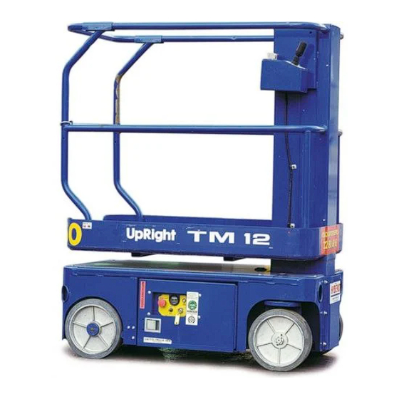
- Page 1 TM12 UI 12 M-Lift Work Platform Serial Numbers M30176 - M30642 Publication Number: 107100-000...
- Page 2 Serial Numbers M30176 – M30642 When contacting UpRight for service or parts information, be sure to include the MODEL and SERIAL NUMBERS from the equipment nameplate. Should the nameplate be missing, the SERIAL NUMBER is also stamped on top of the chassis above the front axle pivot.
- Page 3 This manual consists of five (5) parts. P E R A T O R A N U A L A copy of the Operator Manual that is stored on every UpRight Aerial Work Platform. 1 - G E C T I O N...
- Page 4 Foreword Page ii Service Manual...
- Page 5 PERATION ANUAL TM12 — Ui 12 M-LIFT Serial Numbers M30176 – M30642 WARNING All personnel shall carefully read, understand and follow all safety rules, operating instructions, and the Scaffold Industry Association’s MANUAL OF RESPONSIBILITIES of ANSI A92.6-1999 before performing maintenance on or operating any Ui Aerial Work Platform..
-
Page 6: Table Of Contents
Specifications ...............17 Page 2 Operation Manual | TM12 — Ui 12 M-LIFT | 107100-101... -
Page 7: Introduction
Introduction NTRODUCTION This manual covers all models of the Ui 12 M-LIFT Aerial Work Platform. This manual must be stored on the machine at all times. Read, understand and follow all safety rules and operating instructions before attempting to operate the machine. -
Page 8: Special Limitations
Whole trees sway. It is difficult to walk against the wind. D A N G E R Never operate the machine with a platform load greater than the rated capacity. Page 4 Operation Manual | TM12 — Ui 12 M-LIFT | 107100-101... -
Page 9: Controls And Indicators
1. Joystick 2. Emergency Stop 3. Lift Button 4. Drive Button 5. Emergency Stop (chassis) 6. Toggle switch (chassis) 7. Enable button 8. Keyswitch 9. Horn Button 10. Display 107100-101 | TM12 — Ui 12 M-LIFT | Operation Manual Page 5... -
Page 10: Pre-Operation Safety Inspection
7. Inspect the machine thoroughly for cracked welds and structural damage, loose or missing hardware, hydraulic leaks, damaged control cable and loose wire connections. 8. Ensure that all safety labels are in place and in good condition before operating. Page 6 Operation Manual | TM12 — Ui 12 M-LIFT | 107100-101... -
Page 11: System Function Inspection
16. Push the Steering Switch RIGHT then LEFT to check for steering control. 17. Push the Platform Emergency Stop Switch down to the OFF position. All machine functions should be disabled. Pull out the Platform Emergency Stop Switch to resume. 107100-101 | TM12 — Ui 12 M-LIFT | Operation Manual Page 7... -
Page 12: Operation
O W E R I N G L A T F O R M 1. Select LIFT mode. 2. While depressing the Interlock Switch, pull back on the Control Lever. Page 8 Operation Manual | TM12 — Ui 12 M-LIFT | 107100-101... -
Page 13: Emergency Lowering
2. Park the machine on a firm level surface, preferably under cover, secure against vandals, children and unauthorized operation. 3. Turn the Chassis Key Switch to OFF and remove the key to prevent unauthorized operation. 107100-101 | TM12 — Ui 12 M-LIFT | Operation Manual Page 9... -
Page 14: Transporting The Machine
C A U T I O N Overtightening of the chains or straps attached to the Tie Down lugs may result in damage to the machine. Forklift From Side Typical Tie Down/Lift Points (D-Rings) Page 10 Operation Manual | TM12 — Ui 12 M-LIFT | 107100-101... -
Page 15: Maintenance
4. Check the fluid level on the dipstick on the filler cap. 5. Add the appropriate fluid to bring the level to the FULL mark. See “” on page 20 107100-101 | TM12 — Ui 12 M-LIFT | Operation Manual Page 11... -
Page 16: Battery Maintenance
DO NOT use tap water with high mineral content, as it will shorten battery life. • Keep the terminals and tops of the batteries clean. • Refer to the Service Manual to extend battery life and for complete service instructions. Page 12 Operation Manual | TM12 — Ui 12 M-LIFT | 107100-101... -
Page 17: Battery Charging
• Lights remain ON until the AC power supply is disconnected. NOTE: The battery charger circuit must be used with a GFI (Ground Fault Interrupt) outlet. DO NOT operate the machine while the charger is plugged in. 107100-101 | TM12 — Ui 12 M-LIFT | Operation Manual Page 13... -
Page 18: Inspection And Maintenance Schedule
The daily preventative maintenance checklist has been designed for machine service and maintenance. Please photocopy the Daily Preventative Maintenance Checklist and use the checklist when inspecting the machine. Page 14 Operation Manual | TM12 — Ui 12 M-LIFT | 107100-101... -
Page 19: Daily Preventative Maintenance Checklist
Platform Deck and Elevating Assembly Inspect for structural cracks. Check condition of deck. Rails Emergency Hydraulic Operate the emergency lowering valve and Tires Check for damage. System check for serviceability. 107100-101 | TM12 — Ui 12 M-LIFT | Operation Manual Page 15... -
Page 20: Labels
These labels shall be present and in good condition before operating the machine. Be sure to read, under- stand and follow these labels when operating the machine. Figure 13: Safety Label Locations | Serial # M30176 - M30338 Page 16 Operation Manual | TM12 — Ui 12 M-LIFT | 107100-101... - Page 21 DO NOT use ladders or scaffolding on platform DO NOT climb down mast. 066550-001 DOWN 066556-001 REVERSE UpRight LIFT DRIVE 014222-003-99 CUTOUT CUTOUT 107051-000 EMERGENCY STOP 061220-002 8 107050-000 107100-101 | TM12 — Ui 12 M-LIFT | Operation Manual Page 17...
- Page 22 Labels Figure 15: Safety Label Locations - European ITT | Serial # M30339 - M30642 Page 18 Operation Manual | TM12 — Ui 12 M-LIFT | 107100-101...
- Page 23 Secure gate across enterance. DO NOT use ladders or scaffolding on the platform. DO NOT climb down linkage. 503723-000 503723-000 505076-000 7 505078-000 503723-000 014222-903 014222-903 107052-000 107053-000 107052-000 107100-101 | TM12 — Ui 12 M-LIFT | Operation Manual Page 19...
- Page 24 Labels Figure 17: Safety Labels Locations - Domestic ITT | Serial # M30339 - M30642 Page 20 Operation Manual | TM12 — Ui 12 M-LIFT | 107100-101...
-
Page 25: Specifications
*Specifications are subject to change without notice. Hot weather or heavy use may affect performance. Refer to the Service Manual for complete parts and service information. This machine meets or exceeds ANSI A92.6 1999 directive requirements. 107100-101 | TM12 — Ui 12 M-LIFT | Operation Manual Page 21... - Page 26 Specifications OTES Page 22 Operation Manual | TM12 — Ui 12 M-LIFT | 107100-101...
- Page 27 Table 1-5: Specific Gravity and Battery Voltage ......... 1-13 Table 1-6: Battery Charging, UpRight Electric and BiEnergy Machines ..... . . 1-14 Table 1-7: Battery Charger Troubleshooting .
-
Page 28: Hazard Indicators
UpRight, Inc., might be done, or of the possible hazardous consequences of each conceivable way, nor could UpRight Inc. investigate all such ways. Anyone using service procedures or tools, whether or not recommended by UpRight Inc., must satisfy themselves thoroughly that neither personal safety nor... -
Page 29: Torque Specifications
O M P O N E N T S NOTE: Always lubricate threads with clean hydraulic fluid prior to installation Use the following values to torque hydraulic components used on UpRight Aerial Work Platforms. Table 1-1: Torque Specifications for Hydraulic Components... -
Page 30: Table 1-3: Torque Specifications For Metric Fasteners, U.s. Customary Units
Torque Specifications Section 1 - General Information Table 1-3: Torque Specifications for Metric Fasteners, U.S. Customary Units 12.9 10.9 Grade 12.9 Grade 10.9 Grade 8.8 Nominal Tightening Torque Tightening Torque Tightening Torque Clamp Clamp Clamp Thread Load Load Load K =,15 K =,20 K =,15 K =,20... -
Page 31: Date Code Identification On Hoses
• Optimizer with adapter (UpRight P/N 100329-000) • Flow Meter Kit (UpRight P/N 067040-000) • Quadragauge with fitting (UpRight P/N 063971-000) • 0-25 kg (0-50 Lbs.) Chain Tension Scale (UpRight P/N 107078-000) IGHT • Gland Nut Wrench (UpRight P/N 062521-000) •... -
Page 32: Upright Connectors
UpRight Connectors Section 1 - General Information 1-6 U IGHT ONNECTORS UpRight connectors are designed so that connector parts, contacts or electrical cables may be replaced without replacing the entire connector. Figure 1-1: UpRight Connector Kits Small Kit Large Kit... -
Page 33: Figure 1-4: Locking Finger, Upright Connector
E L E A S I N G O C K I N G I N G E R S Figure 1-4: Locking Finger, UpRight Connector 1. The Locking Fingers can be released following the removal of the Locking Wedge of either the male or female connector. -
Page 34: Hydraulic Manifold Repair
Hydraulic Manifold Repair Section 1 - General Information 1-7 H YDRAULIC ANIFOLD EPAIR E M O V A L Refer to the Service and Repair section for model specific information. 1. Disconnect the battery. 2. Tag and disconnect the solenoid valve leads. 3. -
Page 35: Cylinder Repair
Section 1 - General Information Cylinder Repair 1-8 C YLINDER EPAIR W A R N I N G Cylinders may be very heavy. Support heavy cylinders before removing pins which secure the cylinder to the machine. E M O V A L NOTE: Refer to the Service and Repair section for the location of cylinders, and the Parts Manual for a list of parts which secure the cylinders. -
Page 36: Electric Motors
Electric Motors Section 1 - General Information 1-9 E LECTRIC OTORS R O U B L E S H O O T I N G Figure 1-6: Electric Motor Service 1. Read the nameplate to become familiar with Ammeter the motor, especially the rated voltage. Power 2. -
Page 37: Figure 1-7: Electric Motor Brushes
Section 1 - General Information Electric Motors N S P E C T I O N Once the motor has been disassembled, go through the following check-list steps to determine where the problem lies. 1. Bearings should spin smoothly and easily and have ample lubrication and be free of corrosion. 2. -
Page 38: Battery Maintenance
Battery fluid is highly corrosive. Thoroughly rinse away any spilled fluid with clean water. Always replace batteries with UpRight batteries or manufacturer approved replacements. Before disconnecting the battery negative (-) lead, make sure all switches are OFF. If ON, a spark will occur at the ground terminal which could cause an explosion if hydrogen gas or fuel vapors are present. -
Page 39: Table 1-5: Specific Gravity And Battery Voltage
A T T E R Y H E C K Electric UpRight Aerial Work Platforms use deep cycle batteries. If poor service life is experienced, batter- ies should be checked for bad cells. Fully charge batteries for 14 hours minimum, ensuring that the charger has completed its cycle (see ‘Battery Charging”... -
Page 40: Table 1-6: Battery Charging, Upright Electric And Bienergy Machines
4. Connect the other end of the extension cord to a grounded AC outlet of proper current, voltage and fre- quency rating. 5. The charger turns on automatically after a short delay. Table 1-6 illustrates charging indicators. Table 1-6: Battery Charging, UpRight Electric and BiEnergy Machines Charger Display AC Charging Current... -
Page 41: Table 1-7: Battery Charger Troubleshooting
If the problem is not resolved after going through the entire table, the charger should be replaced. NOTE: The majority of chargers returned to UpRight as “failed” test good. Please follow the troubleshooting procedures carefully. Table 1-7: Battery Charger Troubleshooting... -
Page 42: Floor Loading
Localized Pressure or Occupied Pressure. To calculate Floor Loading, find the Total Weight of the machine. TOTAL WEIGHT = MACHINE WEIGHT + MAXIMUM PLATFORM CAPACITY. Refer to the machine specifications or contact UpRight or your UpRight dealer. O C A L I Z E D R E S S U R E ²... -
Page 43: Hydraulic Fluid
Unless recommended by UpRight, do not mix hydraulic fluids of different brands or types. The required additives and fluid viscosities may vary. If the use of hydraulic fluids other than listed below is desired please contact UpRight Product Support. OBILFLUID •... -
Page 44: Long Term Storage
Long Term Storage Section 1 - General Information 1-13 L TORAGE NOTE: Do not drain the hydraulic system prior to long term storage. If the machine is to be placed in long term storage, follow these recommended preservation procedures. R E S E R V A T I O N 1. - Page 45 This section contains instructions for the maintenance of the Work Platform. Refer to the General Informa- tion section for information relevant to all UpRight work platforms. Referring to the Operator Manual will aid in understanding the operation and function of the various components and systems of the work plat- form, and help in diagnosing and repair of the machine.
- Page 46 Section 2 - Service and Repair 2-7 Hydraulics ..............2-10 Hydraulic Oil Tank And Filter .
-
Page 47: Supporting Elevating Assembly
Section 2 - Service and Repair Supporting Elevating Assembly 2-1 S UPPORTING LEVATING SSEMBLY W A R N I N G Never perform service on the work platform in the elevating assembly area while platform is elevated without first blocking the elevating assembly. DO NOT stand in elevating assembly area while deploying or storing brace. -
Page 48: Preventative Maintenance
Preventative Maintenance Section 2 - Service and Repair 2-2 P REVENTATIVE AINTENANCE The complete inspection consists of periodic visual and operational checks, along with periodic minor adjustments to assure proper performance. Daily inspection will prevent abnormal wear and prolong the life of all systems. -
Page 49: Preventative Maintenance Check List
Section 2 - Service and Repair Preventative Maintenance Check List 2-3 P REVENTATIVE AINTENANCE HECK REVENTATIVE AINTENANCE REVENTATIVE AINTENANCE EPORT Interval Date: _______________________________________ Daily=each shift or every day Owner:______________________________________ 50h/30d=every 50 hours or 30 days 250h/6m=every 250 hours or 6 months Model No: ___________________________________ 1000h/2y=every 1000 hours or 2 years Serial No: ___________________________________... -
Page 50: Parts Location
Parts Location Section 2 - Service and Repair 2-4 P ARTS OCATION Figure 2-2: Parts Location | Serial # M30176 — M30338 Controller Assembly 107010-000 Dip Switch Settings Dip Switch Fuse Settings 010148-000 Motor Control 065708-001 Circuit Board 065709-001 Relay 010122-000 Control Cable Assembly... - Page 51 Section 2 - Service and Repair Parts Location Figure 2-3: Parts Location - ITT | Serial # M30179 — M30642 Controller Assembly 505005-000 Motor Control 502492-000 502483-000 Fuse 502494-000 Control Cable Assembly 107009-000 Electrical Box Line Contactor Assembly 502489-000 107123-000 Hydraulic Hydraulic Oil Reservoir...
-
Page 52: General Lubrication
General Lubrication Section 2 - Service and Repair 2-5 G ENERAL UBRICATION Figure 2-4: Lubrication Points • Apply grease to each grease fitting. G Grease # Oil • Apply one or two drops of motor oil to each bearing. 1. King Pin Bearings 2. -
Page 53: Batteries
Battery fluid is highly corrosive. Thoroughly rinse away any spilled fluid with clean water. Always replace batteries with UpRight batteries or manufacturer approved replacements. Before disconnecting the battery negative (-) lead, make sure all switches are OFF. If ON, a spark will occur at the ground terminal which could cause an explosion if hydrogen gas or fuel vapors are present. -
Page 54: Hydraulics
Hydraulics Section 2 - Service and Repair 2-7 H YDRAULICS Y D R A U L I C A N K I L T E R LUID EVEL Figure 2-6: Hydraulic Oil Tank and Filter With Platform fully lowered, oil should be visible on 1. -
Page 55: Hydraulic Pump
Section 2 - Service and Repair Hydraulics Y D R A U L I C U M P The Hydraulic Pump is located in the Power Module, and is mounted on the rear of the motor. EMOVAL NOTE: If the hydraulic tank has not been drained, suitable means for plugging the hoses should be provided to prevent excessive fluid loss. - Page 56 Hydraulics Section 2 - Service and Repair Y L I N D E R V A L V E S S E M B L Y Figure 2-8: Cylinder Valve MERGENCY ALVE The Emergency Down Valve located at the front of the machine.
- Page 57 Section 2 - Service and Repair Hydraulics A I N Y D R A U L I C A N I F O L D Though it is not necessary to remove the manifold to perform all maintenance procedures, a determination should be made prior to beginning as to whether or not the manifold should be removed before mainte- nance procedures begin.
- Page 58 Hydraulics Section 2 - Service and Repair Figure 2-10: Hydraulic Manifold | Serial # M30339 — M30642 1. TEST PORT (1/4”) 12. CHECK VALVE (POTHOLE) 2. FITTING (1/4” - 1/4” MALE/MALE) 13. CROSS LINE RELIEF VALVE (DRIVE) 3. FITTING (1/4” - 1/4” MALE/MALE) 14.
- Page 59 Section 2 - Service and Repair Hydraulics E T T I N G Y D R A U L I C A N I F O L D R E S S U R E S W A R N I N G The hydraulic oil may be of sufficient temperature to cause burns.
- Page 60 Hydraulics Section 2 - Service and Repair OUNTERBALANCE ALVES 1. Operate the work platform for 10-15 minutes to bring the hydraulic oil up to normal operating tempera- ture. 2. Remove the gauge port cap and install the pressure gauge assembly. 3.
-
Page 61: Cylinders
Section 2 - Service and Repair Cylinders 2-8 C YLINDERS E P R E S S I O N Y L I N D E R Figure 2-13: Depression Cylinder Remove & Replace EMOVAL 1. Mark and disconnect the hose assemblies from the cylinder fittings and immediately cap the openings to prevent foreign material from enter-... -
Page 62: Brake Cylinder
Cylinders Section 2 - Service and Repair R A K E Y L I N D E R The brake cylinder is located inside the right rear chassis wall above the wheel. Figure 2-14: Brake Cylinder, Remove & Replace EMOVAL 1. -
Page 63: Steering Cylinder
Section 2 - Service and Repair Cylinders T E E R I N G Y L I N D E R EMOVAL Figure 2-15: Steering Cylinder Remove & Replace 1. Mark and disconnect the hose assemblies from the cylinder fittings and immediately cap the openings to prevent foreign material from enter- ing. -
Page 64: Lift Cylinder
Cylinders Section 2 - Service and Repair I F T Y L I N D E R EMOVAL Refer to Figure 2-19: “Elevating Assembly,” on page 2-22 for details. Figure 2-17: Lift Cylinder Seal Kit 1. Fully lower platform. 2. Provide a suitable container to catch the hydraulic fluid, then disconnect the hydraulic hose. -
Page 65: Drive Motors
Section 2 - Service and Repair Drive Motors 2-9 D RIVE OTORS E M O V A L 1. Use a 1000Kg (one ton) capacity jack to raise the front of the machine. Position blocks under the machine to prevent the work platform from falling if the jack fails. 2. -
Page 66: Elevating Assembly
Elevating Assembly Section 2 - Service and Repair 2-10 E LEVATING SSEMBLY Maintenance of the elevating assembly consists of four separate tasks and maintenance intervals: • Chain Lubrication ..... . . 6 months •... -
Page 67: Elevating Assembly Wear Inspection
Section 2 - Service and Repair Elevating Assembly I F T H A I N U B R I C A T I O N Refer to Figure 2-19: “Elevating Assembly,” on page 2-22. With platform in the stowed position; •... -
Page 68: Chain Tension Inspection
Elevating Assembly Section 2 - Service and Repair H A I N E N S I O N N S P E C T I O N Refer to Figure 2-19: “Elevating Assembly,” on page 2-22. The lifting chains are self-adjusting and should always be close to the same tension. This tension should be checked annually to ensure that there are no problems with this system. -
Page 69: Removal Of Elevating Assembly
Section 2 - Service and Repair Elevating Assembly E M O V A L O F L E V A T I N G S S E M B L Y Refer to Figure 2-19: “Elevating Assembly,” on page 2-22. 1. -
Page 70: Tilt Sensor
Tilt Sensor Section 2 - Service and Repair 2-11 T ENSOR W A R N I N G Never perform service on the work platform in the elevating assembly area while platform is elevated without first blocking the elevating assembly. DO NOT stand in elevating assembly area while deploying or storing brace. -
Page 71: Controls
Section 2 - Service and Repair Controls 2-12 C ONTROLS L A T F O R M O N T R O L S The Proportional Controller can be disassembled to replace defective switches. See the Parts Manual for replacement part numbers. Figure 2-22: Upper Controls | Serial # M30176 —... - Page 72 Controls Section 2 - Service and Repair Figure 2-23: Upper Controls | Serial # M30339 — M30642 Boot, Steering Rocker Rocker, Steering Handle Switch, Interlock Emergency Boot, Handle Stop Switch Mounting Plate Decal Lift/Drive Upper Control Box Selector Buttons Page 2-28 TM12 Work Platform |...
-
Page 73: Chassis Controls
Section 2 - Service and Repair Controls H A S S I S O N T R O L S The chassis control assembly is mounted on the inside of the chassis door, to the left of the Hydraulic tank. It is secured to the door with Four carriage bolts (1/4-20UNC x 3/4). Figure 2-24: Chassis Controls | Serial # M30176 —... -
Page 74: Motor Controller And I/O Board Dip Switch Settings | Serial # M30176 - M30338
Motor Controller and I/O Board Dip Switch Settings | Serial # M30176 — M30338 Section 2 - Service and Repair 2-13 M I/O B OTOR ONTROLLER AND OARD WITCH # M30176 — M30338 ETTINGS ERIAL NOTE: - Before dip switch settings will take effect, power must be disconnected or Emergency Stop switches must be depressed. -
Page 75: Table Of Contents
Section 3 ROUBLESHOOTING This section contains troubleshooting Truth Tables. Careful inspection and accurate analysis of the symptoms listed in the Troubleshooting Guide will localize the trouble more quickly than any other method. This manual cannot cover all possible problems that may occur. -
Page 76: Ist Of
Section 3 - Troubleshooting IST OF IGURES Figure 3-1: Hydraulic Test Port ..............2-3 Figure 3-2: Controller . -
Page 77: Technical Support
Use the charts on the following pages to help determine the cause of a fault in your UpRight work platform NOTE: Spike protection diodes at components have been left out of the charts to eliminate confusion. -
Page 78: Motor Controller Dip Switch Settings
Motor Controller Dip Switch Settings Section 3 - Troubleshooting 3-4 M OTOR ONTROLLER WITCH ETTINGS # M30176 - M30338 E R I A L Figure 3-2: Controller E F A U L T W I T C H E T T I N G S The table shows the default dip switch settings on the control- ler box when the machine leaves the factory. -
Page 79: I/O Board Dip Switch Settings
Section 3 - Troubleshooting I/O Board Dip Switch Settings 3-5 I/O B OARD WITCH ETTINGS # M30176 - M30338 E R I A L Figure 3-3: I/O Board E F A U L T E T T I N G S The table shows the default dip switch settings on the I/O board when the machine leaves the factory. -
Page 80: Led Fault Codes
LED Fault Codes Section 3 - Troubleshooting 3-6 LED F AULT ODES # M30176 - M30338 E R I A L Batteries must be fully charged before troubleshooting. Check/Repair all connections before replacing any components Figure 3-4: Motor Controller B– Terminal LED Indicator M2 Terminal B+ Terminal... -
Page 81: Leds At I/O Board
Section 3 - Troubleshooting LEDs at I/O Board 3-7 LED I/O B S AT OARD # M30176 - M30338 E R I A L LED ON REEN The Green LED indicates that power is present at the board. LED ON The Red LED indicates a short in the system. -
Page 82: I/O Board Inputs And Outputs
I/O Board Inputs and Outputs Section 3 - Troubleshooting 3-8 I/O B OARD NPUTS AND UTPUTS # M30176 - M30338 E R I A L Refer to Figure Figure 3-5: “I/O Board,” on page 3-7. ERFORM ESTS WITH ULLY HARGED ATTERIES Battery state of charge will affect readings. - Page 83 Section 3 - Troubleshooting I/O Board Inputs and Outputs Table 3-3: Connector J2 CONTINUOUS PIN DESCRIPTION CONDITION VOLTAGE TO PIN Lift Up requested J2-1 Depression mechanism activation (extend) — Lift Up not requested J2-2 Not Used — — — Upper & Lower E-Stops closed J2-3 24 Volt supply for solenoids J4-5 &...
- Page 84 I/O Board Inputs and Outputs Section 3 - Troubleshooting Table 3-5: Connector J4 CONTINUOUS PIN DESCRIPTION CONDITION VOLTAGE TO PIN Drive, Lift or Steer requested J4-1 Motor Start relay and Hourmeter activation — Drive, Lift or Steer not requested Upper & Lower E-Stops closed J4-2 24 Volt supply to Keyswitch —...
-
Page 85: Fault Codes Introduction
Section 3 - Troubleshooting Fault Codes Introduction 3-9 F AULT ODES NTRODUCTION # M30176 - M30338 E R I A L AULT ODES INTRODUCTION The TM12 is equipped with a fault detection system, if you have a faulty component, bad electri- cal connection or start up error a fault code will be displayed on the read out located on the upper control box. -
Page 86: 3-10 Fault Codes
FAULT CODES Section 3 - Troubleshooting 3-10 FAULT CODES # M30339 - M30642 E R I A L 01 – S YSTEM INITIALIZATION ERROR 02 – S YSTEM COMMUNICATION ERROR 22 – P LATFORM WITCH AT POWER 23 – P LATFORM IGHT WITCH... -
Page 87: Electric
Section 3 - Troubleshooting Electric 3-11 E LECTRIC L L M A C H I N E S Table 3-7: Electrical Troubleshooting Table Component Alarm--ALM Batteries--BAT Battery Charger--CHG 5 AMP Circuit Breaker--F1 175 AMP Fuse--F2 Hour Meter/Low Voltage indicator--HM I/O Board--I/O Motor Control--MC Motor--MOT Motor Relay--R1... - Page 88 Hydraulic Section 3 - Troubleshooting 3-12 H YDRAULIC A C H I N E S Table 3-8: Hydraulic Troubleshooting Table Component Check Valve--CV Steering Cylinder--CYL2 Lift Cylinder--CYL1 Depression Mechanism Cylinder--CYL3 Brake Cylinder--CYL5 Priority Flow Divider--DVDR Suction Strainer--FL1 Return Filter--FL2 Drive Motors (2)--MOT Pump--PMP Main Relief Valve--RV3 Steering Relief Valve--RV1...
-
Page 89: Able Of Ontents
Section 4 CHEMATICS This section contains electrical and hydraulic power schematics and associated information for maintenance pur- poses. The diagrams are to be used in conjunction with the Troubleshooting Truth Tables in Section 3. They allow under- standing of the makeup and functions of the systems for checking, tracing, and faultfinding during troubleshooting analysis. -
Page 90: Hydraulic
Electric Schematic | Serial # M30176-M30338 Section 4 - Schematics 4-1 E # M30176-M30338 LECTRIC CHEMATIC ERIAL Legend: 107016-001 Electric Schematic DESIGNATION NAME FUNCTION LOCATION Upper Controller Alarm Provides warning sound Chassis Controls Assembly Batteries Provides power to work platform Battery Tray Battery Charger Charges battery... - Page 91 Section 4 - Schematics Electric Schematic | Serial # M30176-M30338 SOL9 SOL8 SOL7 SOL6 SOL5 SOL4 SOL3 SOL2 SOL1 TM12 Work Platform | Page 4-3...
-
Page 92: Hydraulic Schematic | Serial # M30176-M30338
Hydraulic Schematic | Serial # M30176-M30338 Section 4 - Schematics 4-2 H # M30176-M30338 YDRAULIC CHEMATIC ERIAL Legend: 107015-001 Hydraulic Schematic Legend DESIGNATION NAME FUNCTION LOCATION Flow Control Valve Assembly Allows Depression Mechanism to Check Valve Hydraulic Manifold retract in drive mode Provides force to turn front CYL1 Steering Cylinder... - Page 93 Section 4 - Schematics Hydraulic Schematic | Serial # M30176-M30338 TM12 Work Platform | Page 4-5...
-
Page 94: Schematic (J1 Harness) | Serial # M30339-M30642
Schematic (J1 Harness) | Serial # M30339-M30642 Section 4 - Schematics 4-3 S (J1 H ) | S # M30339- CHEMATIC ARNESS ERIAL M30642 Page 4-6 TM12 Work Platform |... -
Page 95: Cable Assembly (J1 Harness) | Serial # M30339-M30642
Section 4 - Schematics Cable Assembly (J1 Harness) | Serial # M30339-M30642 4-4 C (J1 H ) | S # M30339- ABLE SSEMBLY ARNESS ERIAL M30642 TM12 Work Platform | Page 4-7... -
Page 96: Electric Schematic | Serial # M30339-M30642
Electric Schematic | Serial # M30339-M30642 Section 4 - Schematics 4-5 E # M30339-M30642 LECTRIC CHEMATIC ERIAL Page 4-8 TM12 Work Platform |... -
Page 97: Hydraulic Schematic | Serial # M30339-M30642
Section 4 - Schematics Hydraulic Schematic | Serial # M30339-M30642 4-6 H # M30339-M30642 YDRAULIC CHEMATIC ERIAL TM12 Work Platform | Page 4-9... - Page 98 Section 4 - Schematics OTES Page 4-10 TM12 Work Platform |...
- Page 99 ARTS ANUAL This document lists and illustrates the replaceable assemblies and parts of this product, as manufactured by Ui Distribution America, Inc. Each parts list contains the component parts for that assembly. Each parts list contains the component parts for that assembly. ONTENTS Final Assembly Lift Cylinder...
-
Page 100: Final Assembly 107000-000 | Serial # M30176-M30338
107000-000 | Serial # M30176-M30338 | Final Assembly Final Assembly 107000-000 | Serial # M30176-M30338 | ITEM PART NO. DESCRIPTION ITEM PART NO. DESCRIPTION 011829-006 BOLT 1/4-20UNC CARRIAGE X 3/4 065543-000 COVER 4M 011248-004 LOCKNUT 1/4-20UNC HEX 065536-000 TOP COVER 011240-004 WASHER 1/4 DIA STD FLAT 065580-001 PLATFORM WELDMENT 101182-006 CABLE ASSY W/ CONNECTOR... - Page 101 107000-000 | Serial # M30176-M30338 | Final Assembly Drawing # 1 of 2 TM12 Work Platform Parts Manual Page 3...
- Page 102 107000-000 | Serial # M30176-M30338 | Final Assembly Drawing # 2 of 2 Page 4 TM12 Work Platform Parts Manual...
- Page 103 O T E S TM12 Work Platform Parts Manual Page 5...
-
Page 104: Basic Assembly
107001-001 Basic Assembly Basic Assembly 107001-001 ITEM PART NO. DESCRIPTION ITEM PART NO. DESCRIPTION 011828-010 SCREW, 1/4-20 X 1 1/4 FH 065562-001 INNER MOUNT 011821-006 SCREW, 1/4-20 X 3/4 BH 065561-001 ANCHOR INNER 012553-012 SCREW 1/4-20UNC SOC HD x 1 1/2 107082-000 ADAPTER 6MB-6MJ X 9”... - Page 105 107001-001 Basic Assembly TM12 Work Platform Parts Manual Page 7...
-
Page 106: Chassis Assembly, 1 Of 4
107002-010 Chassis Assembly, 1 of 4 Chassis Assembly, 1 of 4 107002-010 ITEM PART NO. DESCRIPTION ITEM PART NO. DESCRIPTION 064397-003 NUT ACORN 10-24 NC 107133-000 CHASSIS WELDMENT TM12 011709-004 SCREW MRDHD 10-24UNC x 1/2 065465-000 BATTERY PAN WELDMENT 026553-008 RIVET 3/16 X .501-.625 GRIP 065472-000 SHOE PARK BRAKE 011256-012 SCREW HHC 1/2-13UNC x 1 1/2 065384-000 BRAKE BEARING... -
Page 107: Chassis Assembly, 2 Of 4
107002-010 Chassis Assembly, 2 of 4 Chassis Assembly, 2 of 4 107002-010 ITEM PART NO. DESCRIPTION ITEM PART NO. DESCRIPTION 011248-008 NUT HEX 1/2-13 UNC 101125-001 MOTOR HYDRAULIC 010092-011 WASHER THRUST 1 1/2 065393-003 WHEEL, DRIVE 027931-068 BEARING 1 1/2 107186-000 WHEEL YOKE, L.H. -
Page 108: Chassis Assembly, 3 Of 4
107002-010 Chassis Assembly, 3 of 4 Chassis Assembly, 3 of 4 107002-010 ITEM PART NO. DESCRIPTION ITEM PART NO. DESCRIPTION 114072-000 FITTING 3/4 HOSE #4601-12-10-NWO 107133-000 CHASSIS WELDMENT 013919-010 CLAMP HOSE 065392-021 WHEEL IDLER 011829-006 CARRIAGE BOLT 1/4-20 x 3/4 011786-014 BUSHING MACHINE 1 3/4 I.D. -
Page 109: Chassis Assembly, 4 Of 4
107002-010 Chassis Assembly, 4 of 4 Chassis Assembly, 4 of 4 107002-010 ITEM PART NO. DESCRIPTION ITEM PART NO. DESCRIPTION 107061-000 FLOW CONTROL VALVE ASSY 107179-000 GUARD WELDMENT-L.H. 010122-001 RELAY 107180-000 GUARD WELDMENT-R.H. 011248-005 NUT HEX 5/16-18 027931-063 BRONZE BUSHING #AA 710-27 011240-005 WASHER 5/16 FLAT 113053-000 CYLINDER DEPRESSION ASSY 011253-018 SCREW HHC 5/16-18 X 2 1/4... -
Page 110: Hose Kit
107011-020 | Serial # M30176-M30338 | Hose Kit Hose Kit 107011-020 | Serial # M30176-M30338 | ITEM PART NO. DESCRIPTION ITEM PART NO. DESCRIPTION 061351-025 HOSE ASSY 1/8 X 40 (4FJX-4FJX) 065419-042 HOSE ASSY 1/4 X 42 (6FJX-6FJX) 107313-024 HOSE ASSY 3/16 X 24(4FJX-4FJX X LONG 90) 107092-041 HOSE ASSY 1/4 X 41 (6FJX-6FJX 90) 114074-027 HOSE ASSY 3/8 X 27 (6FJX90-6G8MBX45) 107092-025 HOSE ASSY 1/4 X 25 (6FJX-6FJX 90) - Page 111 107011-020 | Serial # M30176-M30338 | Hose Kit TM12 Work Platform Parts Manual Page 13...
-
Page 112: Hose Kit
505007-000 | Serial # M30339-M30642 | Hose Kit Hose Kit 505007-000 | Serial # M30339-M30642 | ITEM PART NO. DESCRIPTION ITEM PART NO. DESCRIPTION 501999-000 DRIVE MOTOR 057107-000 FILTER (HYDRAULIC OIL) 505037-000 HYDRAULIC CYLINER (LIFT) 505107-000 HYD HOSE (BLOCK - BRAKE CYL, ANNULAR) 505101-000 HYDRAULIC HOSE (MOTOR TO MOTOR) 503800-000 HYDRAULIC MANIFOLD BLOCK 505099-000 HYDRAULIC HOSE (BLOCK TO MOTOR, LH) DI - LH... - Page 113 505007-000 | Serial # M30339-M30642 | Hose Kit TM12 Work Platform Parts Manual Page 15...
-
Page 114: Control Valve Assembly 101120-021 | Serial # M30176-M30338
101120-021 | Serial # M30176-M30338 | Control Valve Assembly Control Valve Assembly 101120-021 | Serial # M30176-M30338 | ITEM PART NO. DESCRIPTION ITEM PART NO. DESCRIPTION 064845-000 3 POS - 4 WAY SOLENOID W/ COILS 100020-040 CONTROL VALVE BLOCK 101120-035 COUNTERBALANCE VALVE 012004-002 FITTING #2 PLUG 011941-008 FITTING STR 8MB-4MJ 012004-004 FITTING #4 PLUG... -
Page 115: Control Valve Assembly 503800-000 | Serial # M30339-M30642
503800-000 | Serial # M30339-M30642 | Control Valve Assembly Control Valve Assembly 503800-000 | Serial # M30339-M30642 | ITEM PART NO. DESCRIPTION ITEM PART NO. DESCRIPTION 503804-000 VALVE, SOLENOID (DRIVE) TEST PORT 503805-000 VALVE, SOLENOID (DRIVE/LIFT) 058358-000 FITTING, 1/4” - 1/4” MALE/MALE 503803-000 CROSS LINE RELIEF VALVE (DRIVE) 058358-000 FITTING, 1/4”... -
Page 116: Controller Assembly 107010-000 | Serial # M30176-M30338
107010-000 | Serial # M30176-M30338 | Controller Assembly Controller Assembly 107010-000 | Serial # M30176-M30338 | ITEM PART NO. DESCRIPTION ITEM PART NO. DESCRIPTION 066805-011 CONTACT BLOCK 107157-000 CONTROL COVER 066805-006 PUSHBUTTON 107159-000 CONTROLLER WELDMENT 063956-003 CONN 12 PIN MATE N LOC 066805-002 SWITCH, SELECTOR - 2 POSITION 064462-029 HOLE PLUG 068807-010 KEY (NOT SHOWN) -
Page 117: Pq Controller 065512-000 | Serial # M30176-M30338
065512-000 | Serial # M30176-M30338 | PQ Controller PQ Controller 065512-000 | Serial # M30176-M30338 | ITEM PART NO. DESCRIPTION 063953-001 CAP, RUBBER 065512-013 ROCKER, PIN 063953-007 SWITCH, INTERLOCK 065512-015 SWITCH, STEERING 065512-016 HANDLE HALF, RIGHT 065512-017 HANDLE HALF, LEFT 065512-018 BOOT, HANDLE TM12 Work Platform Parts Manual Page 19... -
Page 118: Electrical Box Assembly 107008-000 | Serial # M30176-M30338
107008-000 | Serial # M30176-M30338 | Electrical Box Assembly Electrical Box Assembly 107008-000 | Serial # M30176-M30338 | ITEM PART NO. DESCRIPTION ITEM PART NO. DESCRIPTION 011811-004 SCREW,10-32 SELF-TAP x 1/2 107123-000 BOX, ELECT. WELDMT 066805-006 SWITCH HEAD-MUSHROOM 107148-000 BOX TOP 066807-001 ALARM, DUAL TONE 066805-004 SWITCH KEY SELECTOR 015752-000 HOUR METER... -
Page 119: Level Sensor Wire Assembly
029945-020 Level Sensor Wire Assembly Level Sensor Wire Assembly 029945-020 ITEM PART NO. DESCRIPTION 029945-011 LEVEL SENSOR PQ #40000-00006 067456-000 PLUG 3 CONTACT DT 06-3S 067456-002 WEDGE W3S-PO12 068762-001 CONTACT SOCKET 067456-005 BOOT DT3S-BT TM12 Work Platform Parts Manual Page 21... -
Page 120: Control Cable 107009-000 | Serial # M30176-M30338
107009-000 | Serial # M30176-M30338 | Control Cable Control Cable 107009-000 | Serial # M30176-M30338 | ITEM PART NO. DESCRIPTION ITEM PART NO. DESCRIPTION 068760-000 PLUG 12 SOCKET, DEUTSCH #DT06-12SA 065394-002 CORD RETRACT 18 AWG 12 COND 068761-001 LOCKING WEDGE 12 PIN, DEUTSCH #W12S 029601-006 CONN RING 22-18 GA. -
Page 121: Lower Control Cable 107193-000 | Serial # M30176-M30338
107193-000 | Serial # M30176-M30338 | Lower Control Cable Lower Control Cable 107193-000 | Serial # M30176-M30338 | ITEM PART NO. DESCRIPTION ITEM PART NO. DESCRIPTION 029450-099 WIRE 16 AWG BLU 4 FT 029601-011 CONN RING 16-14 GA. #6 DIA. 029475-099 WIRE 16 AWG BLU/BLK 4 FT 029601-014 CONN RING 16-14 GA. -
Page 122: Chassis Control Cable 107194-001 | Serial # M30176-M30338
107194-001 | Serial # M30176-M30338 | Chassis Control Cable Chassis Control Cable 107194-001 | Serial # M30176-M30338 | ITEM PART NO. DESCRIPTION ITEM PART NO. DESCRIPTION 029451-099 WIRE 16 AWG WHT 2.5 FT 068760-018 PLUG 8 SOCKET, DEUTSCH#DT06-8SC 029351-099 WIRE 16 AWG BLK/WHT 4 FT 068762-001 CONTACT SOCKET, DEUTSCH#0460-209-16141 029359-099 WIRE 16 AWG RED/GRN... -
Page 123: Capacitor Harness 107054-001 | Serial # M30176-M30338
107054-001 | Serial # M30176-M30338 | Capacitor Harness Capacitor Harness 107054-001 | Serial # M30176-M30338 | ITEM PART NO. DESCRIPTION ITEM PART NO. DESCRIPTION 063956-012 SOCKET, CONTACT (AMP #350550-1) 101245-001 CAPACITOR (KEMET P/N C340C225M5U5CA) CAP HOUSING (AMP #1-480699-0) 029620-002 CONN BUTT 16-14 GA INSL PLUG HOUSING (AMP #1-480698-0) 029610-006 CONN FORK TERM 16-14 GA #6 LOCK HEAT SHRINK, 1/8”... -
Page 124: Valve Block Cable 107192-000 | Serial # M30176-M30338
107192-000 | Serial # M30176-M30338 | Valve Block Cable Valve Block Cable 107192-000 | Serial # M30176-M30338 | 029450-099 WIRE 16 AWG BLU 1.5 FT 068760-008 8 SOCKET PLUG, DEUTSCH#DT06-8SA 029457-099 WIRE 16 AWG GRN 1.5 FT 068762-001 CONTACT SOCKET, DEUTSCH#0460-209-16141 029453-099 WIRE 16 AWG ORG 1 FT 068764-000 SEAL PLUG, DEUTSCH#114017... -
Page 125: Lift Cylinder
107060-001 Lift Cylinder Lift Cylinder 107060-001 Item Part Description QTY. LIFT CYLINDER SEAL KIT STANDPIPE ADAPTOR EMERGENCY DOWN VALVE ADAPTOR (EMERGENCY DOWN VALVE) 3&4 TM12 Work Platform Parts Manual Page 27... -
Page 126: Brake\Steer Cylinder
065397-003 Brake\Steer Cylinder Brake\Steer Cylinder 065397-003 Item Part Description QTY. SEAL KIT, BRAKE/STEER CYLINDER FITTING, 1/8 - 1/8 (M/M) FITTING, 1/8 M/F BLOCK 90 3&2 Page 28 TM12 Work Platform Parts Manual... -
Page 127: Depression Cylinder
113053-000 Depression Cylinder Depression Cylinder 113053-000 Item Part Description QTY. SEAL KIT, POTHOLE CYLINDER EMERGENCY RELEASE VALVE HANDLE (T-PIECE) EMERGENCY REL VALVE BUSHING FITTING, 1/4 - 1/8 (M/M) FITTING, 1/8 - 1/8 (M/M) TM12 Work Platform Parts Manual Page 29... -
Page 128: Drive Relief Valve Assembly 107006-000 | Serial # M30176-M30338
107006-000 | Serial # M30176-M30338 | Drive Relief Valve Assembly Drive Relief Valve Assembly 107006-000 | Serial # M30176-M30338 | ITEM PART NO. DESCRIPTION 107006-001 VALVE BLOCK 107006-002 VALVE, DRIVE RELIEF 011934-004 FITTING, 90°, 6MB - 6MJ 011935-003 FITTING, 45°, 6MB - 6MJ TORQUE DRIVE RELIEF VALVE TO 35 - 40 FT. -
Page 129: Flow Control Valve 107061-000 | Serial # M30176-M30338
107061-000 | Serial # M30176-M30338 | Flow Control Valve Flow Control Valve 107061-000 | Serial # M30176-M30338 | ITEM PART NO. DESCRIPTION 063924-008 VALVE, FLOW CONTROL 1.5GMP 107062-000 VALVE BODY 011941-005 FITTING, 6MB-6MJ 011934-003 FITTING, 6MB-4MJ X 90° 011934-004 FITTING, 6MB-6MJ X 90° TM12 Work Platform Parts Manual Page 31... -
Page 130: Hydraulic Tank Assembly
107066-000 Hydraulic Tank Assembly Hydraulic Tank Assembly 107066-000 ITEM PART NO. DESCRIPTION 107065-000 HYDRAULIC TANK - ROTAMOLDING 114067-000 RETURN FILTER - TANK IMMERSED 114068-000 SUCTION STRAINER - 3/4 HOSE BARB 068982-001 CAP - HYDRAULIC OIL 107084-000 FITTING 90 BARB - 1/4 NPT Page 32 TM12 Work Platform Parts Manual... -
Page 131: Label Kit
066555-000 LABEL RELIEF VALVE 066554-000 LABEL BEFORE OPERATING 066568-000 LABEL LOWER PLATFORM 107050-000 LABEL CONTROLLER 066556-000 LABEL COLLISION HAZARD 061683-003 LABEL UPRIGHT 066522-000 LABEL BATTERY CHARGER 101250-000 LABEL MAX LOAD 500 LBS. 101252-000 LABEL MAX WHEEL LOAD (675 LBS) 061684-014 LABEL TM12... -
Page 132: Voltage/Hourmeter Option 107032-000 | Serial # M30176-M30338
107032-000 | Serial # M30176-M30338 | Voltage/Hourmeter Option Voltage/Hourmeter Option 107032-000 | Serial # M30176-M30338 | ITEM PART NO. DESCRIPTION 107008-000 ELECTRICAL BOX ASSY 029959-000 VOLTAGE/HOUR METER Page 34 TM12 Work Platform Parts Manual... -
Page 133: Lift Overload Option 107030-000 | Serial # M30176-M30338
107030-000 | Serial # M30176-M30338 | Lift Overload Option Lift Overload Option 107030-000 | Serial # M30176-M30338 | ITEM PART NO. DESCRIPTION ITEM PART NO. DESCRIPTION 029825-003 DIODE - 3A 4OOV 063921-004 PRESSURE SWITCH 029601-011 CONNECTOR - RING (16-14GA) #6 011923-003 FITTING - ADAPTOR (4FP-6MP) 029620-002 CONNECTOR - BUTT (16-14GA) 014048-001 FITTING - COUPLING (6FP-6FJX) -
Page 134: Horn Option
107031-000 | Serial # M30176-M30338 | Horn Option Horn Option 107031-000 | Serial # M30176-M30338 | ITEM PART NO. DESCRIPTION ITEM PART NO. DESCRIPTION 011238-004 WASHER, 1/4 SPLIT LOCK CONTROLLER ASSY 029620-002 CONN BUTT 16-14 066805-018 SWITCH, PUSH BUTTON GE 029601-011 CONN RING 16-14 GA #6 066805-010 CONTACT BLOCK, NO 029601-014 CONN RING 16-14 GA 1/4”... -
Page 135: Hydraulic Schematic 107015-001 | Serial # M30176-M30338
107015-001 | Serial # M30176-M30338 | Hydraulic Schematic Hydraulic Schematic 107015-001 | Serial # M30176-M30338 | TM12 Work Platform Parts Manual Page 37... -
Page 136: Electrical Schematic 107016-000 | Serial # M30176-M30338
107016-000 | Serial # M30176-M30338 | Electrical Schematic Electrical Schematic 107016-000 | Serial # M30176-M30338 | Page 38 TM12 Work Platform Parts Manual... -
Page 137: Itt Electrical Schematic | Serial # M30339-M30642
| Serial # M30339-M30642 | ITT Electrical Schematic ITT Electrical Schematic | Serial # M30339-M30642 | J1-2A J1-1C J1-1A J1-1B P4-A P4-B P4-C P4-D P4-E P4-G P4-H J1-9B J1-11A J1-10C J1-10B TM12 Work Platform Parts Manual Page 39... -
Page 138: Itt Controller | Serial # M30339-M30642
| Serial # M30339-M30642 | ITT Controller ITT Controller | Serial # M30339-M30642 | ITEM PART NO. DESCRIPTION ITEM PART NO. DESCRIPTION 251801 WIRE 22AWG RED 14.5" 8860020201 BOOT RETAINER 251809 WIRE 22AWG BLACK 14.5" 501882-002 RUBBER BOOT 251806 WIRE 22AWG VIOLET 12.5"... - Page 139 | Serial # M30339-M30642 | ITT Controller TM12 Work Platform Parts Manual Page 41...
-
Page 140: Itt Controller Assembly | Serial # M30339-M30642
| Serial # M30339-M30642 | ITT Controller Assembly ITT Controller Assembly | Serial # M30339-M30642 | 220494 SEAL 601064 JOYSTICK 251456 PRINTED CIRCUIT BOARD JOYSTICK RUBBER BOOT 220488 UPPER CONTROL BOX (BOX ONLY) JOYSTICK STEERING BOOT 220695 EMERGENCY STOP BUTTON ASSEMBLY 251428 OVERLAY 220964... - Page 141 | Serial # M30339-M30642 | ECU | Serial # M30339-M30642 | ITEM PART DESCRIPTION 221101 EXTRUSION ALUMINUM 220966 END PLATE, ECU 220606 END PLATE, ECU 251898 ASM, PCB ECU, COATED 100728 LUBRICANT, NYOGEL 760G 220562 SCREW, #6-32, HEX WASHER HEAD 220737 ITT WARRANTY SEAL 220718...
-
Page 142: Itt Control Cable Assembly | Serial # M30339-M30642
| Serial # M30339-M30642 | ITT Control Cable Assembly ITT Control Cable Assembly | Serial # M30339-M30642 | ITEM PART DESCRIPTION ITEM PART DESCRIPTION 220963 HORN, 335hZ, 24VDC 310014 ASSY, PLATFORM CONTROLLER TM12 220696 CONTACT BLOCK, N.C. 310031 ASSY, MOTOR CONTROLLER ALARM COMPARTMENT 220109 SWITCH LOCK 310011... - Page 143 | Serial # M30339-M30642 | ITT Control Cable Assembly TM12 Work Platform Parts Manual Page 45...
-
Page 144: Itt Universal Compartment | Serial # M30339-M30642
| Serial # M30339-M30642 | ITT Universal Compartment ITT Universal Compartment | Serial # M30339-M30642 | ITEM PART NO. DESCRIPTION ITEM PART NO. DESCRIPTION 230028 CABLE ASSY, LC TO FUSE/LC TO MC B+ 221100 MOUNTING PLATE 220992 WIRE ASSY, LC3 TO LC5 230057 MOTOR CONTROLLER 220492... - Page 145 Call Toll Free in U.S.A. 1-866-843-3350...
- Page 146 UpRight USA 2686 S. Maple Avenue Fresno, California 93725 TEL:(559) 443-6600 FAX:(559) 268-1756 866-843-3 PARTS:1- EMAIL:info@uiditribution.com Call Toll Free in U.S.A. www.uidistribution.com 1-866-843-3350...
Need help?
Do you have a question about the UI 12 M-Lift and is the answer not in the manual?
Questions and answers