Upright TM12 Service & Parts Manual
Aerial work platform
serial numbers 5000 to current
Hide thumbs
Also See for TM12:
- Service & parts manual (102 pages) ,
- Service manual (84 pages) ,
- Operator's manual (26 pages)
Table of Contents
Advertisement
Quick Links
Advertisement
Chapters
Table of Contents
Troubleshooting

Related Manuals for Upright TM12


Summary of Contents for Upright TM12
- Page 1 TM12...
- Page 2 TM12 Aerial Work Platform Serial Numbers 5000 to Current When contacting UpRight for service or parts informa- tion, be sure to include the MODEL and SERIAL NUM- BERS from the equipment nameplate. Should the nameplate be missing, the SERIAL NUMBER is also stamped on top of the chassis above the front axle pivot.
- Page 3 Indicates a potentially hazardous situation which, if not avoided, could result in death or serious injury. C A U T I O N Indicates a potentially hazardous situation which, if not avoided, may result in minor or moderate injury. NOTE: Gives helpful information. TM12 Work Platform - European Page i...
- Page 4 Please understand that these warnings cannot cover all conceivable ways in which service, whether or not recommended by UpRight, Inc., might be done, or of the possible hazardous consequences of each conceivable way, nor could UpRight Inc.
-
Page 5: Table Of Contents
2.9 Specifications ..........2-14 TM12 Work Platform - European... - Page 6 3.4 UpRight Connectors ........
- Page 7 Checking Pump Pressures ........... . .4-2 4.3 UpRight Motor Controller Diagnostics ....... 4-5 4.4 Measured Voltage at I/O Board .
- Page 8 Figure 3-2: Plugs and Receptacles, UpRight Connectors ....... . .
- Page 9 Table 4-5: Hydraulic Truth Table - Model ..........4-8 TM12 Work Platform - European...
- Page 10 Table of Contents - List of Tables OTES Page VI TM12 Work Platform - European...
-
Page 11: Introduction
ENERAL ESCRIPTION The TM12 Work Platform is a self-propelled aerial work platform designed to be used as a means of elevating personnel and equipment and to provide a mobile work platform. Mobility with the platform elevated is automatically limited to the low speed range. -
Page 12: Figure 1-1: Tm12 Work Platform
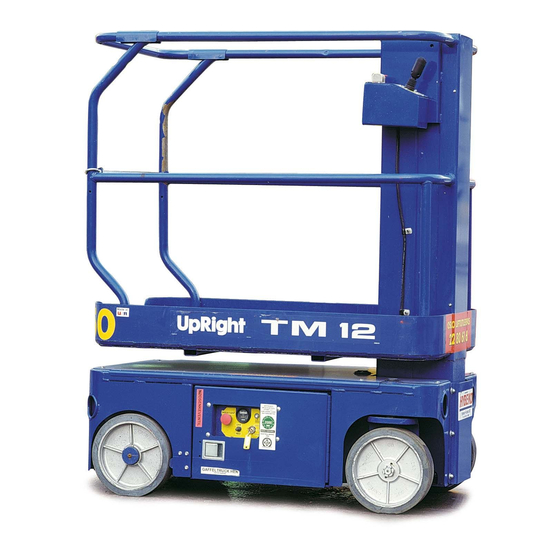
Introduction 1.4 - Specifications 1.4 S PECIFICATIONS The Specifications Table is located at the end of Section 2. Figure 1-1: TM12 Work Platform 1. Platform 2. Controller 3. Mast 4. Chassis Page 1-2 TM12 Work Platform - European... -
Page 13: Specifications
NEVER charge batteries near sparks or open flame. Charging batteries emit explosive hydrogen gas. Modifications to the aerial work platform are prohibited or permissible only at the approval of UpRight. AFTER USE, secure the work platform from unauthorized use by turning both keyswitches off and removing the key. -
Page 14: Operation And Specifications
Operation and Specifications 2.1 - Introduction 2.1 I NTRODUCTION This manual covers operation of the TM12 Self Propelled Elevating Work Platform. This manual must be stored on the machine at all times. 2.2 P PERATION AFETY NSPECTION Carefully read, understand and follow all safety rules, operating instructions, labels and the Scaf- fold Industry Association’s MANUAL OF RESPONSIBILITIES. -
Page 15: Pre-Operation Safety Inspection (Figures 1, 2, And 3)
24. Push the Platform Emergency Stop Switch button to check for proper operation. All machine func- tions should be disabled. Pull out the Platform Emergency Stop Switch to resume. Drive/Lift Switch Platform Emergency Stop Switch TM12 Work Platform - European Page 2-3... -
Page 16: Operation
NOTE: Depression supports will deploy automatically as the platform elevates. Depression supports will retract after; - the platform has been lowered completely, - high speed has been activated, - and the platform has been driven. Page 2-4 TM12 Work Platform - European... -
Page 17: Travel With Platform Elevated
Knob and turning ¼ turn counterclockwise. 2. To close, push in on the knob and turn ¼ turn clockwise until the detent engages. NOTE: The platform will not elevate if the Emergency Lowering Valve is open. TM12 Work Platform - European Page 2-5... -
Page 18: Parking Brake Release
2. Park the machine on a firm, level surface, preferably under cover, secure against vandals, children and unauthorized operation. 3. Turn the Key Switch to OFF and remove the key to prevent unauthorized operation. Page 2-6 TM12 Work Platform - European... -
Page 19: 2.4 - Transporting Work Platform
See specifications for weight of work platform and be certain that forklift is of adequate capacity to lift the work platform. C A U T I O N Overtightening of chains or straps attached to tie down lugs may result in damage to work platform. TM12 Work Platform - European Page 2-7... -
Page 20: Maintenance
2. Remove the wood block. 3. Turn and hold the Chassis Key Switch to CHASSIS. Push the Lift/Lower Switch to DOWN and completely lower platform. Page 2-8 TM12 Work Platform - European... -
Page 21: Battery Maintenance
Battery fluid is highly corrosive. Thoroughly rinse away any spilled fluid with clean water. Always replace batteries with UpRight batteries or manufacturer approved replacements weighing 28 kg (62 lbs.) each. Check the battery fluid level daily, especially if the work platform is being used in a warm, dry climate. -
Page 22: Labels
066555-300 066555-200 066555-400 WARNING - Crushing Hazard 066568-000 066568-300 064915-000 066568-400 CAUTION - Collision Hazard 066556-000 066556-300 066556-200 066556-400 Battery Charger 066522-000 066522-300 066522-200 066522-400 WARNING - Crushing Hazard 066556-001 066556-301 066556-201 066556-401 Page 2-10 TM12 Work Platform - European... - Page 23 Operation and Specifications 2.6 - Labels Label descriptions are on the previous page. English - French - Spanish German TM12 Work Platform - European Page 2-11...
-
Page 24: Preventative Maintenance
The preventative maintenance table has been designed to be used primarily for machine service and maintenance repair. Please photocopy and use the table as a checklist when inspecting the machine for service. Page 2-12 TM12 Work Platform - European... -
Page 25: 2.8 - Preventative Maintenance Check List
Check fasteners for proper torque Daily Check welds for cracks Daily Platform Deck & Rails Check condition of deck Daily Check entry way closure Daily * NOTE: Use ISO #46 during summer and ISO #32 during winter. TM12 Work Platform - European Page 2-13... -
Page 26: Specifications
1,14 m (45 in.) Toeboard 152 mm (6 in.) Specifications are subject to change without notice. Hot weather or heavy use may affect performance. The TM12 meets or exceeds all applicable CE and GS requirements. Page 2-14 TM12 Work Platform - European... -
Page 27: Maintenance
Plant, Year, Month, Day. ARKER i.e.: XXXX 6 11 29 - means Plant XXXX, 1996, month 11 (November), day 29. stamps month, day and year on each hose. AYCO TM12 Work Platform - European Page 3-1... -
Page 28: Special Tools
(UpRight P/N 030898-000) • Inclinometer 3.4 U IGHT ONNECTORS UpRight connectors are designed so that connector parts, contacts or electrical cables may be replaced without replacing the entire connector. Figure 3-1: UpRight Connector Kits Small Kit Large Kit Figure 3-2: Plugs and Receptacles, UpRight Connectors... -
Page 29: Female Connector (Receptacle)
4. Replace or recrimp the wires and contacts. Refer to “Crimping” procedure. ELEASING OCKING INGERS Figure 3-3: Locking Finger, UpRight Connector 1. The Locking Fingers can be released following the removal of the Locking Wedge of either the male or female connector. -
Page 30: Preventative Maintenance
W A R N I N G Before performing preventative maintenance, familiarize yourself with the operation of the machine. The preventative maintenance table in Section 2 has been designed to be used primarily for machine service and maintenance repair. Page 3-4 TM12 Work Platform - European... -
Page 31: Parts Location
107005-000 107008-001 Hydraulic Hydraulic Oil Reservoir Filter Tilt Sensor Assembly 005154-001 Assembly 107007-000 029945-021 Batteries 6 Volt 015796-000 Power Unit 101230-000 Drive Relief Valve Assembly 107006-000 Battery Charger 063948-003 Control Valve Assembly 101120-021 TM12 Work Platform - European Page 3-5... -
Page 32: 3.7 - Supporting Elevating Assembly
1. Push Chassis Lift Switch to UP position and grad- ually raise Platform until wood block can be removed. 2. Remove block. 3. Push Chassis Lift Switch to DOWN position and completely lower Platform Page 3-6 TM12 Work Platform - European... -
Page 33: 3.8 - Battery Maintenance
Before disconnecting the battery negative (-) lead, make sure all switches are OFF. If ON, a spark will occur at the ground terminal which could cause an explosion if hydrogen gas vapors are present. TM12 Work Platform - European Page 3-7... -
Page 34: Battery Charging
Do not check the specific gravity in a cell to which water has just been added. If there is not enough electrolyte in a fully charged cell to obtain a sample for the hydrometer, add water and continue charging for one to two hours to adequately mix the water and electrolyte. Page 3-8 TM12 Work Platform - European... -
Page 35: Lubrication
Figure 3-9: Lubrication Points • Apply grease to each zerk. G Grease # Oil • Apply one or two drops of motor oil to each bearing. 1. King Pin Bearings 2. Steering Linkage 3. Wheel Bearings TM12 Work Platform - European Page 3-9... -
Page 36: Hydraulics
Hydraulic tank has a 7,2 liter (1.9 US gallon) capacity. C A U T I O N The hydraulic oil may be of sufficient temperature to cause burns. Wear safety gloves and safety glasses when handling hot oil. Page 3-10 TM12 Work Platform - European... -
Page 37: Hydraulic Pump
3. Unplug and reconnect the hydraulic hoses. 4. Check the oil level in the hydraulic tank before operating the work plat- 1. Inlet Hose 4. Pump Assembly form. 2. Outlet Hose 5. Electric Motor 3. Capscrew TM12 Work Platform - European Page 3-11... -
Page 38: Hydraulic Valve Assemblies
3. Connect hydraulic hoses. Be certain to tighten hoses to valve block. 4. Install oil filter. 5. Operate each hydraulic function and check for proper function and leaks. Adjust all hydraulic pressures according to instructions in “ Setting Hydraulic Manifold Pressures” on Page 3-16. Page 3-12 TM12 Work Platform - European... -
Page 39: Cylinder Valve Assembly
2. Flow Control Valve (1GPM) 6. Fitting, 90 6JX - 6MJ 3. Solenoid Valve (24 VDC) 7. Fitting, Straight 6MB - 6MJ 4. Plug 1/4 - 18 NPTF 8. Fitting, 90 6MB - 4MJ TM12 Work Platform - European Page 3-13... -
Page 40: Drive Relief Valve Assembly
Relief Valve cover and torque to 8 Nm (6 Ft/Lbs). 7. Remove gauge and replace cap. 1. Valve Block 3. Hose Fitting, 90° 2. Drive Relief Valve 4. Hose Fitting, Straight (torque to 54 Nm [40 ft. lbs.]) Page 3-14 TM12 Work Platform - European... -
Page 41: Main Hydraulic Manifold
2 Position - 4 Way Solenoid Valve with Coil 3 Position - 4 Way Solenoid 12. Coil with Coils 13. Steering Valve 24. Fitting, Plug #4 3 Position - 4 Way Solenoid with Coils TM12 Work Platform - European Page 3-15... -
Page 42: Figure 3-15: Hydraulic Manifold
7. Release the Chassis Lift Switch. 8. Replace the cap, or tighten the locknut on the Lift Relief Valve, and torque to 8 Nm (6 Ft Lbs). 9. Remove the load from the platform Page 3-16 TM12 Work Platform - European... - Page 43 Relief Valve adjusting screw clockwise to increase the pressure until the gauge reads 69 bar (1000 psi). 5. Tighten locknut or replace Steering Relief Valve cover and torque to 8 Nm (6 Ft/Lbs). 6. Remove gauge and replace cap. TM12 Work Platform - European Page 3-17...
-
Page 44: Cylinder Repair
1. Installation is reverse of removal. 2. Carefully remove elevating assembly support. 3. Slowly cycle cylinder several times to remove air from the hydraulic system. 4. Check for proper cylinder operation. Check hydraulic connections for leaks. Page 3-18 TM12 Work Platform - European... -
Page 45: Depression Cylinder
1. Depression Cylinder 3. Cotter Pin 2. Pivot Pin 4. Depression Guard EPAIR Reference: • “3.11 Cylinder Repair” on Page 3-18 Depression Cylinder Seal Kit, Part Number: 065970-011 NSTALLATION Installation is reverse of removal. TM12 Work Platform - European Page 3-19... -
Page 46: Brake Cylinder
6. Lower the machine and operate the drive circuit and check that the brake bars retract and clear the tires when driving and fully engage the tires when stopped. Check for leaks Page 3-20 TM12 Work Platform - European... -
Page 47: Steering Cylinder
3. Head Cap 4. O-Ring 5. Backup Ring 6. Rod Wiper 7. U-Cup 8. Piston 9. Teflon Piston Ring 10. O-Ring (under Piston Ring) 11. Backup Ring (2) 12. O-Ring 13. Piston Nut TM12 Work Platform - European Page 3-21... -
Page 48: Lift Cylinders
5. Install velocity fuse, adapter and fitting into the base of the lift cylinder. 6. Unplug hydraulic hose and attach to the velocity fuse. 7. Test with weight at rated Platform load to check system operation. Check for leaks Page 3-22 TM12 Work Platform - European... -
Page 49: Drive Motors
5. Install the shaft key, wheel, washer and slotted nut. Torque the locknut to 102 Nm (75 Ft/ Lbs). Install a new cotter pin. DO NOT back-off the nut to install cotter pin. 6. Remove blocks, lower the jack and remove. Operate the drive system and check for leaks. TM12 Work Platform - European Page 3-23... -
Page 50: Mast Assembly
6. Remove the can with the hoisting device. 7. Support the inner can with the sling and hoisting device. 8. Remove locknuts, washers and carriage bolts securing the can to the Chassis. 9. Remove the can with the hoisting device. Page 3-24 TM12 Work Platform - European... -
Page 51: Installation
14. Connect the control cable wires to the Controller. 15. Remove the blocking device from the Mast Assembly. 16. Raise and lower the Platform, checking for proper operation and leaks. 17. Install the top mast cover. TM12 Work Platform - European Page 3-25... -
Page 52: Tilt Sensor
2. Support the elevating assembly (see “3.7 Supporting Elevating Assembly” on Page 3-6). 3. Push the level sensor to the side. The red LED should turn on, and the tilt alarm should sound. Page 3-26 TM12 Work Platform - European... -
Page 53: Controls
Rocker, Steering Left Handle Half Switch, Steering Switch, Interlock Right Handle Half Emergency Stop Switch Lever, Interlock Lift/Drive Boot, Handle Selector Switch Emergency Lift/Drive Stop Selector Hall Effect Device Switch Switch 12 Pin Connector TM12 Work Platform - European Page 3-27... -
Page 54: Chassis Controls
Up/Down Toggle Switch cator 4b. Boot Switch Cover Mushroom Emergency 5. Circuit Breaker Stop Switch 6. Alarm, Dual Tone E-Stop Switch Contact 7. Connector Cable, 3/4” Key Chassis/Platform 8. Box Weldment Selector Switch Page 3-28 TM12 Work Platform - European... -
Page 55: 3.16 - Motor Controller And I/O Board Dip Switch Settings
Result Two Speed Mode (not used) Part Serial Proportional Control not used Depression Mechanism extends when platform is raised Down alarm only Down and Reverse alarm Drive and Down alarm All Motion alarm TM12 Work Platform - European Page 3-29... -
Page 56: Electric Motor
• New brush assembly to be installed by reversing above procedure. 4. Inspect wire harness and all connections for signs of damage due to overheating. 5. Check stator to see if it is securely mounted. Page 3-30 TM12 Work Platform - European... -
Page 57: Reassembly
A no-load test can now be performed. At rated voltage, observe the no-load current. It should be less than 20% of the nameplate full load current. Anything higher indicates: • Brushes are not on neutral setting (check match-marks for exact alignment). 10. Faulty armature. TM12 Work Platform - European Page 3-31... -
Page 58: Torque Specifications
PECIFICATIONS YDRAULIC OMPONENTS NOTE: Always lubricate threads with clean hydraulic oil prior to installation Use the following values to torque hydraulic components used on UpRight Work Platforms. Table 3-1: Torque Specifications for Hydraulic Components Type: SAE Part Series Cartridge Poppet... -
Page 59: Table 3-3: Torque Specifications For Metric Fasteners, U.s. Customary Units
285,728 1157 1543 333,923 1352 1803 252,450 1136 1515 349,223 1572 2095 408,128 1837 2450 312,300 1546 2061 432,015 2138 2851 504,885 2500 3332 367,650 1985 2647 508,582 2746 3662 594,368 3210 4279 TM12 Work Platform - European Page 3-33... - Page 60 Maintenance 3.18 - Torque Specifications OTES Page 3-34 TM12 Work Platform - European...
-
Page 61: Troubleshooting
Check/repair/replace each component in the Truth Table which is listed under each machine function which does not operate properly. Use the charts on the following pages to help determine the cause of a fault in your UpRight Work Platform. -
Page 62: Cause And Remedy
UpRight Work Platform. • Flow Meter with Pressure Gauge (UpRight P/N 067040-000) • 0-1000 PSI Hydraulic Pressure Gauge with Adapter Fittings (UpRight P/N 014124-010) • 0-3000 PSI Hydraulic Pressure Gauge with Adapter Fittings (UpRight P/N 014124-030) • Adapter Fitting (UpRight P/N 063965-002) •... -
Page 63: Table 4-1: Cause And Remedy
Test Drive/Lift Switch for continuity. Replace if faulty. drives in reverse. No 2. Faulty Controller Check operation of controller switch. Replace if required. lift function. 3. Faulty Up/Fwd Relay Test Relay. Replace if faulty. TM12 Work Platform - European Page 4-3... - Page 64 1. Brake Orifice plugged Remove and clean Orifice. wheel. 2. Faulty Brake Cylinder Check and replace seals in Brake Cylinder. 3. Brake out of adjustment Adjust nut so brakes fully engage tires when not driving. Page 4-4 TM12 Work Platform - European...
-
Page 65: 4.3 - Upright Motor Controller Diagnostics
Troubleshooting 4.3 - UpRight Motor Controller Diagnostics 4.3 U IGHT OTOR ONTROLLER IAGNOSTICS Batteries must be fully charged before troubleshooting. Check/Repair all connections before replacing any components Table 4-2: Motor Controller Diagnostics Flash Code Meaning Status Corrective Action Power to the controller and the... -
Page 66: 4.4 - Measured Voltage At I/O Board
24 Volts = Line Contactor OFF / 0 Volts = Line Contactor ON 24 Volts = No Direction Solenoid Allowed / 0 Volts = Direction Solenoid Allowed to Activate Accelerator 3.5 Volts to 0 Volts / Minimum to Maximum Speed Page 4-6 TM12 Work Platform - European... -
Page 67: Electric
SOL2 - Steering Solenoid (left) SOL3 - Platform Lift Solenoid SOL4 - Reverse Solenoid SOL5 - Forward Solenoid SOL6 - Depression Mechanism Extension Solenoid SOL7 - Down Solenoid SOL8 & SOL9 - Depression Mechanism Retraction Solenoid TM12 Work Platform - European Page 4-7... -
Page 68: Table 4-5: Hydraulic Truth Table - Model
V1 - Steering Right/Left Valve V2 - Lift Valve V3 - Down/Emergency Lowering Valve V4 - Depression mechanism Retract Valve V5 - Depression Mechanism Extend Valve V6 - Forward/Reverse Valve V7 - Counterbalance Valve Page 4-8 TM12 Work Platform - European... - Page 69 Hydraulic Schematic Legend (107015-000) ........5-4 Tm12 Work Platform - European...
-
Page 70: Figure 3-24: Chassis Controls
Extends depression mechanism Battery Tray MOT (behind charger) SOL6 Hydraulic Manifold Extension bars Solenoid SOL7 Down Solenoid Lowers platform Lift Cylinder Depression SOL8 & Mechanism Retracts depression mechanism Depression SOL9 Retraction bars Mechanism cylinder Solenoid Page 5-2 Tm12 Work Platform - European... - Page 71 Schematics 5.2 - Electric SOL9 SOL8 SOL7 SOL6 SOL5 SOL4 SOL3 SOL2 SOL1 Tm12 Work Platform - European Page 5-3...
- Page 72 Provides oil control for drive or lift Hydraulic Manifold Valve functions Counterbalance Prevents machine from running Hydraulic Manifold Valve away on slopes; cushions stops Velocity Fuse Lock lift cylinder if line breaks Lift Cylinder Block Valve Page 5-4 Tm12 Work Platform - European...
- Page 73 Schematics 5.3 - Hydraulic Tm12 Work Platform - European Page 5-5...
- Page 74 Schematics 5.3 - Hydraulic OTES Page 5-6 Tm12 Work Platform - European...
- Page 75 065512-000 ........6-16 TM12 Work Platform - European...
-
Page 76: Final Assembly
107081-000 WELDMENT, BALLAST 011240-005 WASHER 5/16 STD FLAT 107015-000 HYD SCHM 011248-005 LOCKNUT 5/16-18UNC HEX 107016-001 ELEC SCHM 011253-006 SCREW 5/16-18UNC HHC X 3/4 110010-001 SPECIFICATION SHEET 026616-008 NIPPLE 1 CHASE 029939-004 LOCKNUT 1 NPT Page 6-2 TM12 Work Platform - European... - Page 77 Illustrated Parts Breakdown - Final Assembly Drawing # 1 of 2 TM12 Work Platform - European Page 6-3...
- Page 78 Illustrated Parts Breakdown - Final Assembly Drawing # 2 0f 2 Page 6-4 TM12 Work Platform - European...
- Page 79 Illustrated Parts Breakdown - OTES TM12 Work Platform - European Page 6-5...
-
Page 80: Basic Assembly
013949-003 WASHER #10 EXT. STAR 062642-019 BEARING 7/8 ID X 3/4 LG 063096-010 FUSE VELOCITY 062167-103 CHAIN LEAF 011240-006 WASHER 3/8 STD FLAT 065580-001 PLATFORM WELDMENT 011254-032 SCREW, HHC. 3/8-16 X 4 065366-020 SWITCH, PROXIMITY ASSY Page 6-6 TM12 Work Platform - European... - Page 81 Illustrated Parts Breakdown - Basic Assembly TM12 Work Platform - European Page 6-7...
-
Page 82: Chassis Assembly, 1 Of 4
010414-001 LOCKING PIN ASSY X 6 065656-000 WEAR PAD 015919-004 ORIFICE #824 065368-000 TACK 065352-000 CHANNEL 026553-004 RIVET 3/16 X .250-.375 GRIP 014996-010 WASHER 5/8 SAE 011252-006 SCREW HHC 1/4-20UNC x 3/4 Drawing # 1 of 4 Page 6-8 TM12 Work Platform - European... -
Page 83: Chassis Assembly, 2 Of 4 107002-000
108 011848-041 PIN 3/4 PIVOT 123 011240-008 WASHER FLAT STD 1/2 109 011757-010 COTTER PIN, RUE RING 3/4” 110 011753-012 PIN COTTER 1/8 x 1 1/2 111 065518-000 STEER LINK LH Drawing # 2 of 4 TM12 Work Platform - European Page 6-9... -
Page 84: Chassis Assembly, 3 Of 4 107002-000
228 011248-005 NUT HEX 5/16-18 101230-010 PUMP 229 020032-003 FITTING TEE #6 - NOT SHOWN 015797-011 MOTOR, ELECTRIC 230 020733-001 FITTING TEE #4 212 107152-000 BRACKET, CONTROL VALVE MOUNT 213 065395-000 LATCH 214 107150-000 PANEL WELDMENT RH Page 6-10 TM12 Work Platform - European... - Page 85 Illustrated Parts Breakdown - Chassis Assembly, 3 of 4 Drawing # 3 of 4 TM12 Work Platform - European Page 6-11...
-
Page 86: Chassis Assembly, 4 Of 4 107002-000
339 011248-003 NUT HEX #10-24 318 011248-004 LOCKNUT 1/4-20 HEX 340 011240-006 WASHER 3/8 FLAT 319 011240-004 WASHER 1/4 DIA STD FLAT 320 011252-010 SCREW HHC 1/4-20 X 1 1/4 Drawing # 4 of 4 Page 6-12 TM12 Work Platform - European... -
Page 87: Hose Kit
065369-099 HOSE GUARD NYLON X 18” 107092-020 HOSE ASSY 1/4 X 20 (6FJX-6FJX X 90) 10 107090-035 HOSE ASSY 1/4 X 35 (4FJX-4FJX X 90) 11 107090-029 HOSE ASSY 1/4 X 29 (4FJX-4FJX X 90) TM12 Work Platform - European Page 6-13... - Page 88 Illustrated Parts Breakdown - Hose Kit Page 6-14 TM12 Work Platform - European...
-
Page 89: Control Valve Assembly
060390-013 RELIEF VALVE, STEERING (1500 PSI) 063923-021 3 POS - 4 WAY SOLENOID W/ COILS 060390-025 RELIEF VALVE, MAIN (3000 PSI) 020021-004 FITTING, PLUG #4 063923-006 2 POS - 4 WAY SOLENOID W/ COIL 101120-033 COIL TM12 Work Platform - European Page 6-15... -
Page 90: Controller Assembly
066805-002 SWITCH, SELECTOR - 2 POSITION 011826-004 SCREW 10-32 SLFTP X 1/2 068807-010 KEY (NOT SHOWN) 026525-008 SCREW #8 SLFTP ABHWH X 1 066805-012 CONTACT BLOCK, NO-NC 065512-000 CONTROLLER PQ 066805-011 CONTACT BLOCK Page 6-16 TM12 Work Platform - European... -
Page 91: Pq Controller
Illustrated Parts Breakdown - PQ Controller PQ Controller 065512-000 ITEM PART NO. DESCRIPTION 063953-001 CAP, RUBBER 065512-013 ROCKER, PIN 063953-007 SWITCH, INTERLOCK 065512-015 SWITCH, STEERING 065512-016 HANDLE HALF, RIGHT 065512-017 HANDLE HALF, LEFT 065512-018 BOOT, HANDLE TM12 Work Platform - European Page 6-17... -
Page 92: Electrical Box Assembly
068582-005 CIRCUIT BREAKER 5 AMP 029872-000 BOOT SWITCH COVER 012798-000 SWITCH TOGGLE 066805-010 CONTACT BLOCK 029925-001 CONNECTOR CABLE 3/4 029939-003 LOCKNUT, CONDUIT 3/4 011725-006 SCREW, 1/4-20 UNC PAN HD x3/4 066805-011 SWITCH CONTACT Page 6-18 TM12 Work Platform - European... -
Page 93: Level Sensor Wire Assembly 029945-021
Illustrated Parts Breakdown - Level Sensor Wire Assembly Level Sensor Wire Assembly 029945-021 ITEM PART NO. DESCRIPTION 029945-013 LEVEL SENSOR PQ # M40000-00005 067456-000 PLUG 3 CONTACT DT 06-3S 067456-002 WEDGE W3S-PO12 068762-001 CONTACT SOCKET 067456-005 BOOT DT3S-BT TM12 Work Platform - European Page 6-19... -
Page 94: Cylinder Valve Assembly
011941-005 FITTING STR 6MB-6MJ 063925-002 VALVE SOL 24 VDC 011937-003 FITTING 90 6JX-6MJ 063924-005 VALVE FLOW CONTROL 1 GPM 011934-003 FITTING 90 6MB-4MJ 011920-002 PLUG SOC.HD. 1/4-18 NPTF 063977-001 PLUG 9mm 011934-004 FITTING, 90 6MB-6MJ Page 6-20 TM12 Work Platform - European... -
Page 95: Drive Relief Valve Assembly
107006-001 VALVE BLOCK 107006-002 VALVE, DRIVE RELIEF 011934-004 FITTING, 90°, 6MB - 6MJ 011935-003 FITTING, 45°, 6MB - 6MJ TORQUE DRIVE RELIEF VALVE TO 35 - 40 FT. LBS (47 - 54 Nm) TM12 Work Platform - European Page 6-21... -
Page 96: Hydraulic Tank Assembly
Illustrated Parts Breakdown - Hydraulic Tank Assembly Hydraulic Tank Assembly 107007-000 ITEM PART NO. DESCRIPTION 107127-000 TANK WELDMENT 011939-015 FITTING 8MP-8MJ 061818-000 SUCTION SCREEN/FITTING 021305-006 PLUG, MAGNETIC 005963-001 FILLER BREATHER 005963-010 Gasket Page 6-22 TM12 Work Platform - European... -
Page 97: Label Kit, European 107012-001
066568-000 LABEL LOWER PLATFORM 061683-003 LABEL UPRIGHT 066556-000 LABEL COLLISION HAZARD 066557-051 LABEL MAX LOAD 225 KG 066522-000 LABEL BATTERY CHARGER 061684-014 LABEL TM12 066556-001 LABEL WARNING 010076-000 MANUAL CASE 010076-001 LABEL ATTENTION TM12 Work Platform - European Page 6-23... -
Page 98: Label Kit, German
066568-000 LABEL LOWER PLATFORM 061683-003 LABEL UPRIGHT 066556-200 LABEL COLLISION HAZARD 064910-003 LABEL MAX LOAD 225 KG 066522-200 LABEL BATTERY CHARGER 061684-014 LABEL TM12 066556-201 LABEL WARNING 010076-000 MANUAL CASE 064913-000 LABEL ATTENTION Page 6-24 TM12 Work Platform - European... -
Page 99: Label Kit, French
066568-300 LABEL LOWER PLATFORM 061683-003 LABEL UPRIGHT 066556-300 LABEL COLLISION HAZARD 066557-301 LABEL MAX LOAD 225 KG 066522-300 LABEL BATTERY CHARGER 061684-014 LABEL TM12 066556-301 LABEL WARNING 010076-000 MANUAL CASE 010076-301 LABEL ATTENTION TM12 Work Platform - European Page 6-25... -
Page 100: Label Kit, Spanish 107012-400
066568-400 LABEL LOWER PLATFORM 061683-003 LABEL UPRIGHT 066556-400 LABEL COLLISION HAZARD 066557-401 LABEL MAX LOAD 225 KG. 066522-400 LABEL BATTERY CHARGER 061684-014 LABEL TM12 066556-401 LABEL WARNING 010076-000 MANUAL CASE 010076-401 LABEL ATTENTION Page 6-26 TM12 Work Platform - European... - Page 102 UpRight, Inc. UpRight International Support Centre 1775 Park Street Selma, California 93662 Innsbruckweg 114 3047 AH Rotterdam TEL:559/891-5200 Call Toll Free in U.S.A. Netherlands FAX:559/891-9012 1-800-926-LIFT TEL: +31-10-238-0000 PARTS:1-888-UR-PARTS FAX: +31-10-238-0001 PARTS FAX:559/896-9244 Parts Tel: +31-10-490-8090 Parts Fax: +31-10-490-8099 107099-020...
Need help?
Do you have a question about the TM12 and is the answer not in the manual?
Questions and answers