Table of Contents
Advertisement
Quick Links
Advertisement
Table of Contents

Related Manuals for Advantech SOM-5992


Summary of Contents for Advantech SOM-5992
- Page 1 User Manual SOM-5992 Intel Xeon Processor D-1500 COM Express R3.0 Type 7 Module...
- Page 2 No part of this manual may be reproduced, copied, translated or transmitted in any form or by any means without the prior written permission of Advantech Co., Ltd. Information provided in this manual is intended to be accurate and reliable. How- ever, Advantech Co., Ltd.
-
Page 3: Declaration Of Conformity
Class I, Division 2, Groups A, B, C and D indoor hazards. Technical Support and Assistance Visit the Advantech website at http://support.advantech.com where you can find the latest information about the product. Contact your distributor, sales representative, or Advantech's customer service center for technical support if you need additional assistance. -
Page 4: Packing List
Before setting up the system, check that the items listed below are included and in good condition. If any item does not accord with the table, please contact your dealer immediately. SOM-5992 CPU module 1 x Heatspreader (1960073944N001) SOM-5992 User Manual... -
Page 5: Safety Instructions
The sound pressure level at the operator's position according to IEC 704-1:1982 is no more than 70 dB (A). DISCLAIMER: This set of instructions is given according to IEC 704-1. Advantech disclaims all responsibility for the accuracy of any statements contained herein. - Page 6 Serial Presence Detect – refers to serial EEPROM on DRAMs that has DRAM Module configuration information Trusted Platform Module, chip to enhance the security features of a com- puter system UEFI Unified Extensible Firmware Interface Watch Dog Timer SOM-5992 User Manual...
-
Page 7: Table Of Contents
Figure 3.19CPU P State Control..........39 Figure 3.20XE Ratio Limit............40 Figure 3.21CPU C State Control ..........41 Figure 3.22CPU HWPM State Control........42 Figure 3.23CPU Advanced PM Turning ........43 Figure 3.24DRAM RAPL Configuration ........44 SOM-5992 User Manual... - Page 8 S/W Introduction ..................84 Driver Installation ..................84 4.2.1 Windows Driver Setup ..............84 4.2.2 Other OS..................84 Advantech iManager ................85 Appendix A Assignment......... 87 SOM-5992 Type 7 Pin Assignment............88 Appendix B Watchdog Timer........ 93 SOM-5992 User Manual viii...
- Page 9 Table D.1: System I/O ports............98 DMA Channel Assignments ..............99 Table D.2: DMA Channel Assignments........99 Interrupt Assignments ................99 Table D.3: Interrupt Assignments..........99 1st MB Memory Map ................100 Table D.4: 1st MB Memory Map ..........100 SOM-5992 User Manual...
- Page 10 SOM-5992 User Manual...
-
Page 11: Chapter 1 General Information
Chapter General Information This chapter gives background information on the SOM-5992 CPU Computer on Module. Sections include: Introduction Functional Block Diagram Product Specification... -
Page 12: Introduction
(SANs), network attached storage (NAS) appli- ances, warm cloud storage, and more. In a breakthrough move, SOM-5992 supports a maximum of 64 GB DDR4 memory which should help fulfill the ever-increasing server application demands in the area of COM Express. -
Page 13: Functional Block Diagram
Functional Block Diagram SOM-5992 User Manual... -
Page 14: Product Specification
Power Button Support 1 / 1 Power Good 1 / 1 VCC_5V_SBY Contacts 4 / 4 Sleep Input 0 / 1 Lid Input 0 / 1 Carrier Board Fan Control 0 / 1 Power R3.0 Type 7 SOM-5992 SOM-5992 User Manual... - Page 15 CH-A0 is the first priority for system boot up. Graphics / Audio Intel® Xeon® Processor D Family is without graphics. SOM-5992 does not support display and audio. Graphics will be defined according to specific user scenarios based on system specification.
- Page 16 Intel Xeon® Processor D natively integrates one x16 PCI Express interface sup- porting up to 4 devices at up to Gen3 speeds (8 GHz). SOM-5992 supports one PCIe x16, and is configurable to 2 x8, 1 x8 & 2 x4, or 4 x4.
- Page 17 Smart Fan Supports two Fan PWM control signals and two tachometer inputs for fan speed detection. Provides one on module with connector, and the other on the carrier board following the PICMG COM Express R3.0 specification. SOM-5992 User Manual...
- Page 18 LPC Wake: depends on user inquiry and may need customized BIOS Advantech S5 ECO Mode (Deep Sleep Mode) Advantech iManager provides additional features to allow the system to enter a very low suspend power mode – S5 ECO mode. In this mode, the module will cut all power including suspend and active power into the chipset and keep an on-module controller active.
- Page 19 Link: http://com.advantech.com OS Support (duplicate with SW chapter) The mission of Advantech Embedded Software Services is to "Enhance quality of life with Advantech platforms and Microsoft Windows embedded technology." We enable Windows Embedded software products on Advantech platforms to more effectively support the embedded computing community.
- Page 20 In layout checklist, it will specify the layout con- strains and recommendations for trace length, impedance, and other necessary infor- mation during design. Please contact your nearest Advantech branch office or call for getting the design documents and further advanced support. Link: http://com.advantech.com...
- Page 21 SOM-5992 User Manual...
- Page 22 SOM-5992 User Manual...
-
Page 23: Chapter 2 Mechanical Information
Chapter Mechanical Information This chapter gives mechanical information on the SOM-5992 CPU Computer on Module. Sections include: Board Information Mechanical Drawing Assembly Drawing... -
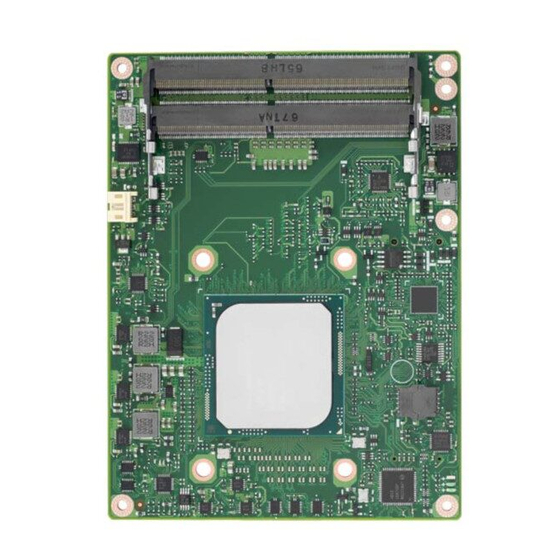
Page 24: Board Information
Board Information The figures below indicate the main chips on SOM-5992 Computer-on-Module. Please aware of these positions while designing your own carrier board to avoid mechanical issues, as well as designing thermal solution contact points for best ther- mal dissipation performance. -
Page 25: Connector List
Wafer 2.0mm 3P 90D(M)DIP 2001-WR-03-LF W/Lock Pin Name Fan Tacho-Input Fan Out Mechanical Drawing For more details about 2D/3D models, find out more on Advantech’s COM support service website Link: http://com.advantech.com Figure 2.3 Board Mechanical Drawing - Front SOM-5992 User Manual... -
Page 26: Figure 2.4 Board Mechanical Drawing - Back
64GB memory, please adopt a H:8mm board-to-board connector on car- rier board. If there is no need for 64GB memory, users can keep the H:5mm board-to-board con- nector on the carrier board. Please contact Advantech sales or FAE for more details. SOM-5992 User Manual... -
Page 27: Assembly Drawing
These figures demonstrate the assembly order from thermal module, to the COM module, to the carrier board. Semi-Cooler Heat Spreader SOM-5992 SOM-DB5920 Screw & Standoff Figure 2.6 Assembly Drawing There are four reserved screw holes for SOM-5992 to be pre-assembled with the heat spreader. SOM-5992 User Manual... -
Page 28: Assembly Drawing
ENCE BOARD DESIGN) Figure 2.7 Main Chip Height and Tolerance Caution! SOM-5992 has a clean area for a thermal solution backplane on the rear side, which is for a thermal module and the backplane is designed to help strengthen the contact of the thermal module and the CPU. If the space is used, please reserve a relative clean area on the carrier board according to the following dimensions. -
Page 29: Chapter 3 Bios Operation
Chapter BIOS Operation This chapter gives BIOS setup information for the SOM-5992 CPU Computer on Module. Sections include: Introduction Entering Setup Hot / Operation Key Exit BIOS Setup Utility... -
Page 30: Entering Setup
Figure 3.1 Setup program initial screen AMI's BIOS ROM has a built-in Setup program that allows users to modify the basic system configuration. This information is stored in flash ROM so it retains the Setup information when the power is turned off. SOM-5992 User Manual... -
Page 31: Entering Setup
System Date using the <Arrow> keys. Enter new values through the keyboard. Press the <Tab> key or the <Arrow> keys to move between fields. The date must be entered in MM/DD/YY format. The time must be entered in HH:MM:SS format. SOM-5992 User Manual... -
Page 32: Advanced Bios Features Setup
3.2.2 Advanced BIOS Features Setup Select the Advanced tab from the SOM-5992 setup screen to enter the Advanced BIOS Setup screen. Users can select any item in the left frame of the screen, such as CPU Configuration, to go to the sub menu for that item. Users can display an Advanced BIOS Setup option by highlighting it using the <Arrow>... -
Page 33: Figure 3.3 Trusted Computing
TPM 1.2 will restrict support to TPM 1.2 devices, TPM 2.0 will restrict support to TPM 2.0 devices, Auto will support both with the default set to TPM 2.0 devices, if not found, TPM 1.2 devices will be enumerated. SOM-5992 User Manual... -
Page 34: Figure 3.4 Acpi Settings
Enables or disables BIOS ACPI Auto Configuration. Enable Hibernation Enables or disables system ability to Hibernate (OS/S4 Sleep State). This option may be not effective with some OS. Lock Legacy Resources Enables or disables Lock of Legacy Resources. SOM-5992 User Manual... -
Page 35: Figure 3.5 Imanager Configuration
Power Saving Mode Select ITE8528 power saving mode Serial Port 1 Configuration Set parameters of serial port 1 (COMA) Serial Port 2 Configuration Set parameters of serial port 2 (COMB) Hardware Monitor Monitor hardware status SOM-5992 User Manual... -
Page 36: Figure 3.6 Serial Port 1 Configuration
Serial Port 1 Configuration Figure 3.6 Serial Port 1 Configuration – Serial Port Enable or disable Serial Port (COM) – Change Settings Select an optimal setting for Super IO device. SOM-5992 User Manual... -
Page 37: Figure 3.7 Serial Port 2 Configuration
Serial Port 2 Configuration Figure 3.7 Serial Port 2 Configuration – Serial Port Enable or disable Serial Port (COM) – Change Settings Select an optimal setting for Super IO device. SOM-5992 User Manual... -
Page 38: Figure 3.8 Hardware Monitor
Hardware Monitor Information This item shows hardware information parameters. Figure 3.8 Hardware Monitor 3.2.2.4 Serial Port Console Redirection Figure 3.9 Serial Port Console Redirection SOM-5992 User Manual... -
Page 39: Figure 3.10Pci Subsystem Settings
Enable or disable PCI Device to generate SERR# – Above 4G Decoding Enables or disables 64-bit capable devices to be decoded in above 4G Address Space (Only if System Supports 64 bit PCI Decoding) – Don’t Reset VC-TC Mapping SOM-5992 User Manual... -
Page 40: Figure 3.11Network Stack Configurations
Enable or disable Ipv6 PXE support. (If disabled IPV6 PXE boot option will not be created). PXE boot wait time Wait time to press ESC key to abort the PXE boot. Media detect count Number of times presence of media will be checked. SOM-5992 User Manual... -
Page 41: Figure 3.12Csm Configuration
Storage Controls the execution of UEFI and legacy storage OpROM Video Controls the execution of UEFI and legacy video OpROM Other PCI devices Determines OpROM execution policy for devices other than network, storage, or video SOM-5992 User Manual... -
Page 42: Figure 3.13Nvme Configuration
3.2.2.7 NVMe Configuration Figure 3.13 NVMe Configuration NVMe Device Options Setting User can start the setting after inserting NVMe device. SOM-5992 User Manual... -
Page 43: Figure 3.14Usb Configuration
Maximum time the device will take before it properly reports itself to the Host Controller. ‘Auto’ uses default value: for a Root port it is 100 ms, for a Hub port the delay is taken from Hub descriptor. AMI Storage Devices SOM-5992 User Manual... -
Page 44: Intelrcsetup
3.2.3 IntelRCSetup Select the IntelRCSetup tab from the SOM-5992 setup screen to enter the BIOS Setup screen. You can select the items by highlighting it using the <Arrow> keys. All Plug and Play BIOS Setup options are described in this section. The Plug and Play BIOS Setup screen is shown below. -
Page 45: Figure 3.16Processor Configuration #1
User defined. Server ME Configuration Configure Server ME Technology parameters. Runtime Configuration Press <Enter> to view or change the runtime error log configuration. Reserve Memory Reserve memory 3.2.3.1 Processor Configuration Figure 3.16 Processor Configuration #1 SOM-5992 User Manual... -
Page 46: Figure 3.17Processor Configuration #2
Enable – MSR 3Ah, MSR 0E2h and CSR 80h will locked. Power good reset is needed to remove locked bits. PPIN Control Unlock and enable/disable PPIN Control. Debug Interface MSR 0C80h bit [0], When set enables debugging features. Hardware Prefetcher = MLC Streamer Prefectcher (MSR 1A4h Bit[0]). SOM-5992 User Manual... - Page 47 MSR CB0_SLICE0_CR_IIO_LLC_WAYS bitmask. QLRU Config [63:32] (Hex) VIRTUAL_MSR_CR_QLRU_CONFIG bitmask. QLRU Config [31:0] (Hex) VIRTUAL_MSR_CR_QLRU_CONFIG bitmask. SMM Save State Enable or disable the SMM Save State feature. Targeted Smi Enable or disable Targeted Smi Feature. SOM-5992 User Manual...
-
Page 48: Figure 3.18Advanced Power Management Configuration
Setting in PCU_MISC_CONFIG Bit [28]. Option to disable/enable Config TDP. IOTG Setting IOTG setting via sticky scratch pad register. Uncore CLR Freq OVRD Override uncore max CLR Freq ratio programming to MSR 0x620 bits [6:0]. SOM-5992 User Manual... -
Page 49: Figure 3.19Cpu P State Control
Boot performance mode Select the performance state that BIOS will set before OS handoff. – Turbo Mode Turbo mode allows a CPU logical processor to execute a higher frequency when enough power is available not exceeding CPU defined limits. SOM-5992 User Manual... -
Page 50: Figure 3.20Xe Ratio Limit
– XE Ratio Limit Figure 3.20 XE Ratio Limit Overclocking Lock Enable/disable Overclocking. SOM-5992 User Manual... -
Page 51: Figure 3.21Cpu C State Control
Enable/disable CPU C6(ACPI C2) report to OS. Recommended to be disabled. Enhances Halt State (C1E) Enable or disable the Enhanced C1E state of the CPU, takes effect after reboot. OS ACPI Cx Report CC3/CC6 to OS ACPI C2 or ACPI C3. SOM-5992 User Manual... -
Page 52: Figure 3.22Cpu Hwpm State Control
3.2.3.4 CPU HWPM State Control Figure 3.22 CPU HWPM State Control HWPM States Enable CPU HWPM for CPU for better energy performance. SOM-5992 User Manual... -
Page 53: Figure 3.23Cpu Advanced Pm Turning
Provide hint to CPU for better performance or power savings. Program PowerCTL_MSR Program PowerCTL MSR 0x1FC Sub Menu Program PRO_CURT_CFG_CTRL_MSR Program PRI_PLANE_CURT_CFG_CTRL_MSR 0x601 Sub Menu. Program CSR_ENTRY_CRITERIA Program CSR_ENTRY_CRITERIA 1:10:2:0x7C Sub Menu. Program CSR_SWL TROVRD Program CSR_SWL TROVRD 1:10:1:0x78 Sub Menu. SOM-5992 User Manual... -
Page 54: Figure 3.24Dram Rapl Configuration
Figure 3.24 DRAM RAPL Configuration DRAM RAPL Baseline DRAM RAPL Baseline enabled and baseline mode. Override BW_LIMIT_TF Allows custom tuning of BW_LIMIT_TF when DRAM RAPL is enabled. DRAM RAPL Extended Range Select DRAM RAPL Extended Range SOM-5992 User Manual... -
Page 55: Figure 3.25Socket Rapl Config
Short Duration Power Limit (aka Power Limit 2) value n Watts. The value may vary from 0 to 32767. Pkg Clmp Lim2 Pkg Clamping limit 2, Allow going below P1. Short Dur Pwr Limit En Enable or disable Short Duration Power Limit (aka Power Limit 2). SOM-5992 User Manual... -
Page 56: Figure 3.26Common Refcode Configuration
MMCFG Base Select MMCFG Base MMIOBase MMIOH Base [63:32] ; must be between 4032 – 4078. MMIO High Size Select MMIO High Size Isoc Mode IsocL Disable, Enable NeSeg Mode MeSeg: Disable, Enable SOM-5992 User Manual... -
Page 57: Figure 3.27Memory Configuration -1
Enable or disable DDR ECC support Enforce Timeout Enable or disable forcing cold reset after three months. Enhanced Log Parsing Enables additional output in debug log for easier machine parsing. Backside RMT Enable backside RMT SOM-5992 User Manual... -
Page 58: Figure 3.28Memory Configuration -2
CH bitmask to apply CECC WA. 1 bit per CH. Value 2 applies WA on CH1, 3 on CH0 and 1. Rank Margin Tool Enables the rank margin tool to run after DDR4 memory training RMT Pattern Length Set the pattern length for the Rank Margin Tool. Figure 3.28 Memory Configuration -2 SOM-5992 User Manual... - Page 59 Opp read during WMM Enable or disable issuing read commands opportunistically during WMM. Normal Operation Duration Set normal operation duration interval (0 - 65535). Number of Sparing Transaction Set number of sparing transactions interval (0 - 65535). SOM-5992 User Manual...
-
Page 60: Figure 3.29Memory Topology
SMB Clock Frequency Sets DDR4 SMB Clock Frequency for SPD Access. DIMM Rank Enable Mask Select ranks to enable or disable per DIMM. Memory Topology Figure 3.29 Memory Topology Display memory topology with DIMM population information. SOM-5992 User Manual... -
Page 61: Figure 3.30Memory Thermal
MDLL Off Enable to shut down MDLL during SR – MEMHOT Throttling Mode Configure MEMHOT Input and Output Mode: Mem Hot Sense Therm Throt or Mem Hot Output Therm Throt. – MEM Electrical Throttling Configure Memory Electrical Throttling SOM-5992 User Manual... -
Page 62: Figure 3.31Memory Power Savings Advanced Options
– Memory Power Savings Advanced Options Figure 3.31 Memory Power Savings Advanced Options Allows users to configure CK behaviors during self-refresh. Memory Timings & Voltage Override Figure 3.32 Memory Timings & Voltage Override SOM-5992 User Manual... - Page 63 4GB. – Channel Interleaving Select Channel Interleaving setting – Rank Interleaving Select Rank Interleaving setting – IOT Memory Buffer Reservation Select IOT Memory Buffer Reservation – A7 Mode A7 Mode disable or enable. SOM-5992 User Manual...
-
Page 64: Figure 3.33Memory Ras Configuration
Memory RAS Configuration Figure 3.33 Memory RAS Configuration Display and provide options to change the memory RAS Settings. 3.2.3.11 IIO Configuration Figure 3.34 IIO Configuration SOM-5992 User Manual... -
Page 65: Figure 3.35Iio Configuration
Enable this option to avoid the system to be halted on DMI width/link degrada- tion. Power Halt on DMI Degradation Power down unused ports IIO Configuration Figure 3.35 IIO Configuration – IOU2 (IIO PCIe Port 1) SOM-5992 User Manual... -
Page 66: Figure 3.36Socket 0 Pcied01F0 - Port 1A
Figure 3.36 Socket 0 PcieD01F0 - Port 1A In auto mode the BIOS will remove the EXP port if there is no device or errors on that device or device is not HP capable. Use disable to hide its CFG space. SOM-5992 User Manual... -
Page 67: Figure 3.37Socket 0 Pcied02F0 - Port 2A
In auto mode the BIOS will remove the EXP port if there is no device or errors on that device or device is not HP capable. Disable is used to disable the port and hide its CFG space. SOM-5992 User Manual... -
Page 68: Figure 3.39Socket 0 Pcied03F0 – Port 3A
In auto mode the BIOS will remove the EXP port if there is no device or errors on that device or device is not HP capable. Disable is used to disable the port and hide its CFG space. IOAT Configuration Figure 3.40 IOAT Configuration SOM-5992 User Manual... -
Page 69: Figure 3.41Iio General Configuration
IIO General Configuration Figure 3.41 IIO General Configuration – TXT DPR memory setting Allow selection of the TXT DPR size in system. – IIO 0 User Defined – IIO IOAPIC Enable or disable the IIO IOAPIC. SOM-5992 User Manual... -
Page 70: Figure 3.42Intel Vt For Directed I/O (Vt-D)
Disable: Programs ACS to all PCIe bridges. – Interrupt Remapping Enable or disable VT-F Interrupt Remapping support. – Coherency Support (Non-Isoch) Enable or disable non-Isoch VT-D Engine Coherency support. – Coherency Support (Isoch) Enable or disable Isoch VT-D Engine Coherency support. SOM-5992 User Manual... -
Page 71: Figure 3.43Iio South Complex Configuration
IIO South Complex Configuration Figure 3.43 IIO South Complex Configuration – SC GbE PF0 (10GbE) Force Enable or disable SC GbE physical function 0. – SC GbE PF1 (10GbE) Force Enable or disable SC GbE physical function 1. SOM-5992 User Manual... -
Page 72: Figure 3.44Pch Configuration
3.2.3.12 PCH Configuration Figure 3.44 PCH Configuration PCH Devices Figure 3.45 PCH Devices SOM-5992 User Manual... - Page 73 Boot time calculation with High Precision Event Timer enabled. – External SSC Enable – CK420 Enable Spread Spectrum – only affects external clock generator. – PCH state after G3 Select S0/S5 for ACPI state after a G3. – PCH CRID Enable or disable PCH’s CRID. SOM-5992 User Manual...
-
Page 74: Figure 3.46Pch Express Configuration
PCIe-USB Glitch W/A PCIe-USB Glitch W/A for bad USB device(s) connected behind PCIE/PEG Port. – PCI Express Root Port 0 ~ 7 Select one of the PCI Express Root Port, press <enter> into the table to change the setting. SOM-5992 User Manual... -
Page 75: Figure 3.47Pch Sata Configuration
PCH SATA Configuration Figure 3.47 PCH SATA Configuration Press <enter> into each option to select SATA devices and settings. Select configuration SATA as AHCI or IDE, default by AHCI. SOM-5992 User Manual... -
Page 76: Figure 3.48Usb Configuration
Control each of the USB ports (0~13) disabling. – xHCI Idle L1 Enabled xHCI Idle L1. Disabled to workaround USB3 hot plug will fail after 1 hot plug removal. Please put the system to G3 for the new settings to take effect. SOM-5992 User Manual... -
Page 77: Figure 3.49Security Configuration
Enable will lock bytes 38h-3Fh in the lower/upper 128-byte bank of RTC RAM. – BIOS Lock Enable or disable the PCH BIOS Lock Enable Feature. – Host Flash Lock-Down Enable or disable Host flash lock-down. – GbE Flash Lock-Down Enable or disable GbE flash lock-down. SOM-5992 User Manual... -
Page 78: Figure 3.50Miscellaneous Configuration
3.2.3.13 Miscellaneous Configuration Figure 3.50 Miscellaneous Configuration Fan PWN Offset Specify fan speed offset. PCIe Max Read Request Size Set Max Read Request Size SOM-5992 User Manual... -
Page 79: Figure 3.51Server Me Configuration
The hex number is decoded as 2’s complement signed integer. Provide the 80000000 value if the altitude is unknown. MCTP Bus Owner MCTP bus owner location on PCIe: [15:8] bus, [7:3] device, [2:0] function. If all zero sending bus owner is disabled. SOM-5992 User Manual... -
Page 80: Figure 3.52Runtime Error Logging
S/W Error Injection Support When Enable S/W Error Injection is supported by unlocking MSR 0x790. Clear McBankErroes Enable or disable clearing McBank errors on warm reset. System Poison Enable or disable core, uncore and IIO poison. SOM-5992 User Manual... -
Page 81: Figure 3.53Reserve Memory
3.2.3.16 Reserve Memory Figure 3.53 Reserve Memory Reserve Memory Range Sets aside an empty memory page that is hidden from the OS. Reserve TAGEC Memory Reserve 16M for TAGEC. SOM-5992 User Manual... -
Page 82: Server Mgmt
3.2.4 Server Mgmt Select the IntelRCSetup tab from the SOM-5992 setup screen to enter the BIOS Setup screen. You can select the items by highlighting it using by the <Arrow> keys. Figure 3.54 Server Mgmt BMC Support Enable or disable interfaces to communicate with the BMC. -
Page 83: Figure 3.55System Event Log
Choose options for erasing SEL. When SEL is Full Choose options for reactions to a full SEL. Log EFI Status Codes Disable the logging of EFI Status Codes or log only error code or only progress code or both. SOM-5992 User Manual... -
Page 84: Figure 3.56Bmc Self Test Log
Logs the report returned by BMC self test command. Figure 3.56 BMC self test log Erase Log Choose Yes or No, to erase log on every reset. When log is full Select the action to be taken when the log is full. SOM-5992 User Manual... -
Page 85: Figure 3.57Bmc Network Configuration
Check configuration BMC network parameters. Figure 3.57 BMC network configuration Configuration Address source Select to configure LAN channel parameters statically or dynamically (by BIOS or BMC). Unspecified options will not modify any BMC network parameters dur- ing BIOS phase. SOM-5992 User Manual... -
Page 86: Figure 3.58Bmc User Settings
3.2.4.4 BMC User Settings Press <Enter> to select the BMC user setting in this page to add or delete user infor- mation. Figure 3.58 BMC User Settings SOM-5992 User Manual... -
Page 87: Security
3.2.5 Security Select the Security tab from the SOM-5992 setup screen to enter the BIOS Setup screen. You can select the items by highlighting it using the <Arrow> keys. All Plug and Play BIOS Setup options are described in this section. The Plug and Play BIOS Setup screen is shown below. -
Page 88: Boot
3.2.6 Boot Select the Boot tab from the SOM-5992 setup screen to enter the BIOS Setup screen. You can select the items by highlighting it using by the <Arrow> keys. Figure 3.60 Boot Setup Prompt Timeout Number of seconds to wait for setup activation key. 65535(0xFFFF) means indefinite waiting. -
Page 89: Event Logs
3.2.7 Event Logs Select the Event Logs tab from the SOM-5992 setup screen to enter the BIOS Setup screen. You can select the items by highlighting it using the <Arrow> keys. Figure 3.61 Event Logs Change Smbios Event Log Settings Press <enter>... -
Page 90: Save & Exit
Save Changes When users have completed system configuration, select this option to save changes without exiting the BIOS setup menu. 3.2.8.6 Discard Changes Select this option to discard any current changes and load the previous system con- figuration. SOM-5992 User Manual... - Page 91 3.2.8.7 Restore Defaults The SOM-5992 automatically configures all setup items to optimal settings when users select this option. Optimal Defaults are designed for maximum system perfor- mance, but may not work best for all computer applications. In particular, do not use the optimal defaults if the user's computer is experiencing system configuration prob- lems.
- Page 92 SOM-5992 User Manual...
- Page 93 Chapter S/W Introduction & Installation Sections include: S/W Introduction Driver Installation Advantech iManager...
-
Page 94: S/W Introduction
S/W Introduction The mission of Advantech Embedded Software Services is to "Enhance quality of life with Advantech platforms and Microsoft Windows embedded technology." We enable Windows Embedded software products on Advantech platforms to more effectively support the embedded computing community. Customers are freed from the hassle of dealing with multiple vendors (Hardware suppliers, System integrators, Embedded OS distributor) for projects. -
Page 95: Advantech Imanager
More details of how to use the APIs and utilities, please refer to the Advantech iManager 2.0 Software API User Manual. SOM-5992 User Manual... - Page 96 SOM-5992 User Manual...
- Page 97 Appendix Pin Assignment This appendix gives you the infor- mation about the hardware pin assignment of the SOM-5992 CPU System on Module. Sections include: SOM-5992 Type 7 Pin Assign- ment...
-
Page 98: A.1 Som-5992 Type 7 Pin Assignment
This section gives SOM-5992 pin assignment on COM Express connector which compliant with COM Express R3.0 Type 7 pin-out definitions. More details about how to use these pins and get design reference. Please contact to Advantech for design guide, checklist, reference schematic, and other hardware/software supports. - Page 99 PCIE_RX9+ PCIE_TX9- PCIE_RX9- PCIE_TX10+ PCIE_RX10+ PCIE_TX10- PCIE_RX10- GND(FIXED) GND(FIXED) PCIE_TX11+ PCIE_RX11+ PCIE_TX11- PCIE_RX11- NCSI_TX_EN VCC_5V_SBY GPI3 VCC_5V_SBY RSVD VCC_5V_SBY RSVD VCC_5V_SBY PCIE_CK_REF+ BIOS_DIS1# PCIE_CK_REF- NCSI_RX_ER GND(FIXED) GND(FIXED) SPI_POWER NCSI_CLK_IN SPI_MISO NCSI_RXD1 GPO0 NCSI_RXD0 SPI_CLK NCSI_CRS_DV SPI_MOSI NCSI_TXD1 SOM-5992 User Manual...
- Page 100 B106 VCC_12V A107 VCC_12V B107 VCC_12V A108 VCC_12V B108 VCC_12V A109 VCC_12V B109 VCC_12V A110 GND(FIXED) B110 GND(FIXED) SOM-5992 ROW C, D GND(FIXED) GND(FIXED) USB_SSRX0- USB_SSTX0- USB_SSRX0+ USB_SSTX0+ USB_SSRX1- USB_SSTX1- USB_SSRX1+ USB_SSTX1+ USB_SSRX2- USB_SSTX2- USB_SSRX2+ USB_SSTX2+ GND(FIXED) GND(FIXED) USB_SSRX3- USB_SSTX3-...
- Page 101 PEG_RX4+ PEG_TX4+ PEG_RX4- PEG_TX4- RAPID_SHUTDOWN PEG_RX5+ PEG_TX5+ PEG_RX5- PEG_TX5- GND(FIXED) GND(FIXED) PEG_RX6+ PEG_TX6+ PEG_RX6- PEG_TX6- PEG_RX7+ PEG_TX7+ PEG_RX7- PEG_TX7- RSVD RSVD PEG_RX8+ PEG_TX8+ PEG_RX8- PEG_TX8- GND(FIXED) GND(FIXED) PEG_RX9+ PEG_TX9+ PEG_RX9- PEG_TX9- RSVD RSVD PEG_RX10+ PEG_TX10+ PEG_RX10- PEG_TX10- SOM-5992 User Manual...
- Page 102 PEG_RX15+ D101 PEG_TX15+ C102 PEG_RX15- D102 PEG_TX15- C103 D103 C104 VCC_12V D104 VCC_12V C105 VCC_12V D105 VCC_12V C106 VCC_12V D106 VCC_12V C107 VCC_12V D107 VCC_12V C108 VCC_12V D108 VCC_12V C109 VCC_12V D109 VCC_12V C110 GND(FIXED) D110 GND(FIXED) SOM-5992 User Manual...
- Page 103 Appendix Watchdog Timer This appendix gives you the infor- mation about the watchdog timer programming on the SOM-5992 CPU System on Module. Sections include: Watchdog Timer Programming...
-
Page 104: Programming The Watchdog Timer
** WDT new driver support automatically selects available IRQ. Only Win XP, Win7 and Win8 support it. In other OS, for details, please refer to iManager & Software API User Manual For details, please refer to iManager & Software API User Manual: SOM-5992 User Manual... -
Page 105: Programming Gpio
Appendix Programming GPIO This Appendix gives the illustra- tion of the General Purpose Input and Output pin setting. Sections include: System I/O Ports... -
Page 106: Gpio Register
GPIO Register GPIO Byte Mapping H/W Pin Name BIT0 GPO0 BIT1 GPO1 BIT2 GPO2 BIT3 GPO3 BIT4 GPI0 BIT5 GPI1 BIT6 GPI2 BIT7 GPI3 For details, please refer to iManager & Software API User Manual. SOM-5992 User Manual... -
Page 107: System Assignments
Appendix System Assignments This appendix gives you the infor- mation about the system resource allocation on the SOM-5992 CPU System on Module. Sections include: System I/O ports DMA Channel Assignments Interrupt Assignments 1st MB Memory Map... -
Page 108: System I/O Ports
Motherboard resources 0800-081F Motherboard resources 0880-0883 Motherboard resources D000-DFFF Intel(R) 8 Series/C220 Series PCI Express Root Port #8 - 8C1E D000-DFFF PCI standard PCI Express to PCI/PCI-X Bridge D000-DFFF ASPEED Graphics Family(WDDM) F020-F03F tandard SATA AHCI Controller SOM-5992 User Manual... -
Page 109: Dma Channel Assignments
Microsoft ACPI-Compliant System IRQ 256~511 Microsoft ACPI-Compliant System IRQ 4294967293 Intel(R) USB 3.0 eXtensible Host Controller - 0100 (Microsoft) IRQ 4294967294 PCI standard PCI Express to PCI/PCI-X Bridge IRQ 4294967247~ Intel(R) I210 Gigabit Network Connection #2 4294967256 SOM-5992 User Manual... -
Page 110: St Mb Memory Map
0xFF000000-0xFFFFFFFF Motherboard resources 0xFEE00000-0xFEEFFFFF Motherboard resources 0xFED12000-0xFED1200F Motherboard resources 0xFED12010-0xFED1201F Motherboard resources 0xFED1B000-0xFED1BFFF Motherboard resources Intel(R) USB 3.0 eXtensible Host Controller - 0100 0xF8600000-0xF860FFFF (Microsoft) Intel(R) 8 Series/C220 Series PCI Express Root Port #8 - 0xF4000000-0xF80FFFFF 8C1E SOM-5992 User Manual... - Page 111 SOM-5992 User Manual...
- Page 112 No part of this publication may be reproduced in any form or by any means, electronic, photocopying, recording or otherwise, without prior written permis- sion of the publisher. All brand and product names are trademarks or registered trademarks of their respective companies. © Advantech Co., Ltd. 2017...
Need help?
Do you have a question about the SOM-5992 and is the answer not in the manual?
Questions and answers