Table of Contents
Advertisement
Quick Links
Advertisement
Table of Contents

Subscribe to Our Youtube Channel
Related Manuals for Advantech SOM-6894


Summary of Contents for Advantech SOM-6894
- Page 1 User Manual SOM-6894...
- Page 2 No part of this manual may be reproduced, copied, translated or transmitted in any form or by any means without the prior written permission of Advantech Co., Ltd. Information provided in this manual is intended to be accurate and reliable. How- ever, Advantech Co., Ltd.
- Page 3 Class I, Division 2, Groups A, B, C and D indoor hazards. Technical Support and Assistance Visit the Advantech website at http://support.advantech.com where you can find the latest information about the product. Contact your distributor, sales representative, or Advantech's customer service center for technical support if you need additional assistance.
- Page 4 Before setting up the system, check that the items listed below are included and in good condition. If any item does not accord with the table, please contact your dealer immediately. SOM-6894 CPU module 1 x Heatspreader (1960062204N001) SOM-6894 User Manual...
- Page 5 The sound pressure level at the operator's position according to IEC 704-1:1982 is no more than 70 dB (A). DISCLAIMER: This set of instructions is given according to IEC 704-1. Advantech disclaims all responsibility for the accuracy of any statements contained herein.
- Page 6 Don't touch any components on the CPU card or other cards while the PC is on. Disconnect power before making any configuration changes. The sudden rush of power as you connect a jumper or install a card may damage sensitive elec- tronic components. SOM-6894 User Manual...
-
Page 7: Table Of Contents
Figure 3.14COM Port 2 Configuration ........28 Figure 3.15Parallel Port Configuration........29 Figure 3.16PC Hardware Monitor ..........30 Figure 3.17iManager Configuration ..........31 Figure 3.18COM 3 Configuration..........32 Figure 3.19COM Port 4 Configuration ........33 Figure 3.20Hardware Monitor ............. 34 SOM-6894 User Manual... - Page 8 4.2.1 Windows Driver Setup ..............58 4.2.2 Other OS..................58 Advantech iManager ................59 Appendix A Assignment......... 61 SOM-6894 Type 6 Pin Assignment............62 Appendix B Watchdog Timer........ 67 Programming the Watchdog Timer ............68 Appendix C Programming GPIO......69 GPIO Register..................
-
Page 9: Chapter 1 General Information
Chapter General Information This chapter gives background information on the SOM-6894 CPU Computer on Module. Sections include: Introduction Specification Functional Block Diagram... -
Page 10: Introduction
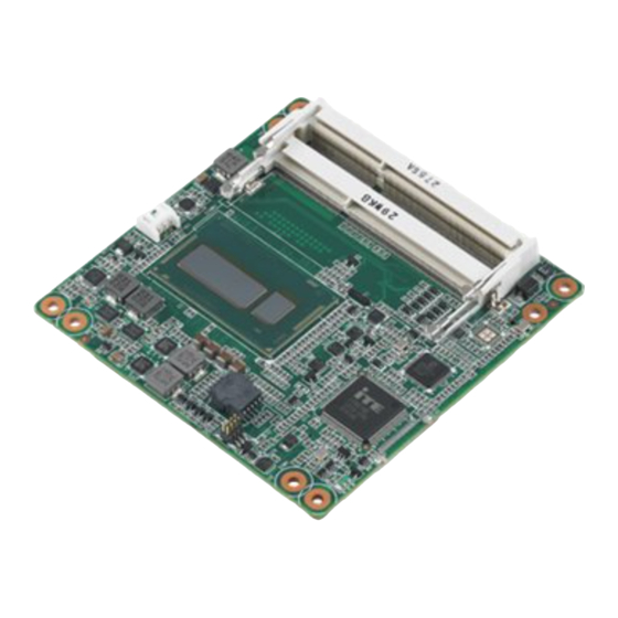
Introduction SOM-6894 is a COM Express Compact module with pin-out Type 6 that fully com- plies with the PICMG (PCI Industrial Computer Manufactures Group) COM.0 R2.1 specification. This product is designed with the latest Intel 4th generation ultra low power processors- Intel® Core™ i7-4650U, i5-4300U, i3-4010U, and Intel® Celeron 2980U which integrates the CPU and PCH onto one single chip. -
Page 11: Display
Thermal Protection: Supports thermal shutdown or CPU throttling Watchdog Timer: 65536 level timer interval, from 0 ~ 65535 sec Smart Fan: 2 Ports; 1 Port on COM Module. Support 12V Fan, 1 Port on Carrier Board SOM-6894 User Manual... -
Page 12: Imanager 2.0
– Test condition: Intel core i7-4650U CPU @ 1.70 GHz, Intel core i5-4300U CPU @ 1.90 GHz, Intel core i3-4010U CPU @ 1.70 GHz, ADVANTECH 8 G DDR3L-1600 I-GRD*2, WIN7 32-bit, Rated voltage DC +4.75 V, +12 V, +21 V –... -
Page 13: Functional Block Diagram
4 PCIe x1 (optional for 1 PCIe x4) DDI 2 HDMI/DisplayPort/DVI (Option with Analog VGA) 1 PCIex1 Giga LAN Intel i218LM LPC BUS (24MHz) WDT / GPIO / I iManager 2.0 RS1 / RS2 / FAN SMBus SPI Bus SPI BIOS SOM-6894 User Manual... - Page 14 SOM-6894 User Manual...
-
Page 15: Chapter 2 Mechanical Information
Chapter Mechanical Information This chapter gives mechanical information on the SOM-6894 CPU Computer on Module. Sections include: Board Information Mechanical Drawing Assembly Drawing... -
Page 16: Board Information
Board Information The figures below indicate the main chips on SOM-6894 Computer-on-Module. Please aware of these positions while designing your own carrier board to avoid mechanical issues, as well as designing thermal solution contact points for best ther- mal dissipation performance. -
Page 17: Mechanical Drawing
Mechanical Drawing For more details about 2D/3D models, please look on the Advantech COM support service website http://com.advantech.com. Figure 2.3 Board Mechanical Drawing - Front Figure 2.4 Board Mechanical Drawing - Back SOM-6894 User Manual... -
Page 18: Assembly Drawing
These figures demonstrate the assembly order from thermal module, COM module to carrier board. Figure 2.5 Assembly Drawing (For Reference Only) There are 4 reserved screw holes for SOM-6894 to be pre-assembled with heat spreader. Figure 2.6 Heatspreader Pre-Assembly (For Reference Only) -
Page 19: Assembly Drawing
DATA FROM INTEL REFERENCE BOARD DESIGN) Figure 2.7 Main Chip Height and Tolerance (GT2) 1.437±0.112 (MILLIMETERS) *F5=NOM : 1.437 TOL:±0.112 (POST SMT STACKUP HEIGHT BASED ON LIMITED DATA FROM INTEL REFERENCE BOARD DESIGN) Figure 2.8 Main Chip Height and Tolerance (GT3) SOM-6894 User Manual... - Page 20 SOM-6894 User Manual...
-
Page 21: Chapter 3 Ami Bios
Chapter AMI BIOS Sections include: Introduction Entering Setup... -
Page 22: Introduction
Figure 3.1 BIOS Setup Utility Main Screen AMI's BIOS ROM has a built-in Setup program that allows users to modify the basic system configuration. This information is stored in flash ROM so it retains the Setup information when the power is turned off. SOM-6894 User Manual... -
Page 23: Entering Setup
System Date using the <Arrow> keys. Enter new values through the keyboard. Press the <Tab> key or the <Arrow> keys to move between fields. The date must be entered in MM/DD/YY format. The time must be entered in HH:MM:SS format. SOM-6894 User Manual... -
Page 24: Advanced Bios Features Setup
3.2.2 Advanced BIOS Features Setup Select the Advanced tab from the SOM-6894 setup screen to enter the Advanced BIOS Setup screen. Users can select any item in the left frame of the screen, such as CPU Configuration, to go to the sub menu for that item. Users can display an Advanced BIOS Setup option by highlighting it using the <Arrow>... - Page 25 This item allows users to enable or disable Lock of Legacy Resources. S3 Video Repost This item allows users to enable or disable S3 Video Repost. ACPI Low Power S0 Idle This item allows users to enable or disable ACPI Low Power S0 Idle support. SOM-6894 User Manual...
- Page 26 Security Device Support This item allows users to enable or disable BIOS support for security device support, and the OS will not show the Security Device. TCG EFI Protocol and INT1A interface will not be available. SOM-6894 User Manual...
- Page 27 This item allows users to enable or disable Hardware Prefetcher. Enable the Mid Level Cache (L2) streamer prefetcher. Adjacent Cache Line Prefetch This item allows users to enable or disable Adjacent Cache Line Prefetch. Enable the Mid Level Cache (L2) prefetching of adjacent cache lines. SOM-6894 User Manual...
- Page 28 Allow re-configuration of TDP levels based on current power and thermal deliv- ery capabilities of the system. Config TDP Lock This item allows users to enable or disable Config TDP Lock. Locks the Config TDP Control register. SOM-6894 User Manual...
- Page 29 This item allows users to enable or disable Serial ATA Ports. – Hot Plug Designates this port as Hot Pluggable. Serial ATA Port 3 – Port 3 This item allows users to enable or disable Serial ATA Port. – Hot Plug SOM-6894 User Manual...
- Page 30 This item allows users to enable or disable TPM Device Selection. (PTT or dTPM. PTT-Enables PTT in SkuMgr dTPM 1.2- Disables PTT in SkuMgr Warn- ing! PTT/dTPM will be disable and all data saved on it will be lost. Firmware Update Configuration Configure Management Engine Technology Parameters SOM-6894 User Manual...
- Page 31 Firmware Update Configuration Figure 3.9 Firmware Update Configuration – ME FW Image Re-Flash This item allows users to enable or disable ME FW Image Re-Flash function. SOM-6894 User Manual...
- Page 32 This item allows users to enable or disable Un-Configure ME. Amt Wait Timer This item allows users to set timer to wait before sending ASF_GET_BOOT _OPTIONS. Disable ME This item allows users to set ME to Soft Temporary disabled. SOM-6894 User Manual...
- Page 33 This item allows users to enable or disable XHCI Hand-off. This is a workaround for OS without XHCI hand-off support. The XHCI owner- ship change should be claimed by XHCI driver. EHCI Hand-off This item allows users to enable or disable EHCI Hand-off. SOM-6894 User Manual...
- Page 34 Figure 3.12 Super IO Configuration COM Port 1 Configuration This item allows user to set Parameters of COM Port 1. COM Port 2 Configuration This item allows user to set Parameters of COM Port 2. SOM-6894 User Manual...
- Page 35 Figure 3.13 COM Port 1 Configuration – COM Port 1 This item allows users to enable or disable the COM Port. – Change settings This item allows users to select an optimal setting for Super IO device. SOM-6894 User Manual...
- Page 36 – Change settings This item allows users to select an optimal setting for the Super IO device. – Device Mode This item allows users to change the Serial Port mode. Select <High Speed> or <Normal Mode> mode. SOM-6894 User Manual...
- Page 37 This item allows users to enable or disable Parallel Port (LPT/LPTE). – Change settings This item allows users to select an optimal setting for the Super IO device. – Device Mode This item allows users to change the Printer Port mode. SOM-6894 User Manual...
- Page 38 Hardware Monitor This item monitors hardware status. Figure 3.16 PC Hardware Monitor SOM-6894 User Manual...
- Page 39 This item allows users to select iManager IRQ number eBrain WatchDog. Backlight Enable Polarity This item allows users to switch Backlight Enable Polarity for Native or Invert. Power Saving Mode This item allows users to select ITE8528 Power Saving Mode. SOM-6894 User Manual...
- Page 40 – Change settings This item allows users to select an optimal setting for the Super IO device. – Device Mode This item allows users to change the Serial Port mode. Select <High Speed> or <Normal mode> mode. SOM-6894 User Manual...
- Page 41 – Change settings This item allows users to select an optimal setting for the Super IO device. – Device Mode This item allows users to change the Serial Port mode. Select <High Speed> or <Normal mode> mode. SOM-6894 User Manual...
- Page 42 Hardware Monitor This item monitor hardware status. Figure 3.20 Hardware Monitor SOM-6894 User Manual...
- Page 43 This item allows users to enable or disable Console Redirection. COM4 Console Redirection This item allows users to enable or disable Console Redirection. EMS Console Redirection This item allows users to enable or disable Console Redirection. SOM-6894 User Manual...
-
Page 44: Chipset
3.2.3 Chipset Select the Chipset tab from the SOM-6894 setup screen to enter the Chipset BIOS Setup screen. You can display a Chipset BIOS Setup option by highlighting it using the <Arrow> keys. All Plug and Play BIOS Setup options are described in this sec- tion. - Page 45 This item allows users to enable or disable PCIE Wake From DeepSx. Wake from DeepSx by the assertion of PCIE. SLP_S4 Assertion Width This item allows users to select a minimum assertion width of the SLP_S4# sig- nal. Restore AC Power Loss SOM-6894 User Manual...
- Page 46 This item allows users to enable or disable Subtractive Decode. – PCI Express Root Port 1 This item allows users to change PCI Express Root Port 1 settings. – PCI Express Root Port 2 This item allows users to change PCI Express Root Port 2 settings. SOM-6894 User Manual...
- Page 47 This item allows users to enable or disable Hot Plug. PCIe Speed This item allows users to select PCIe Speed. Detect Non-Compliance Device This item allows users to enable or disable Detect Non-Compliance Device. If enabled, it will take more time at POST time. SOM-6894 User Manual...
- Page 48 PCI Express Root Port 2 Configuration Figure 3.26 PCI Express Root Port 2 Configuration PCI Express Root Port 2 This item allows users to enable or disable PCI Express Root Port. ASPM Support This item allows users to set the ASPM level. SOM-6894 User Manual...
- Page 49 This item allows users to enable or disable PCIE LTR Configuration Lock. Snoop Latency Ocerride This item allows users to select Snoop Latency Ocerride for PCH PCIE. Non Snoop Latency Ocerride This item allows users to select Non Snoop Latency Ocerride for PCH PCIE. SOM-6894 User Manual...
- Page 50 If enable, it will take more time at POST time. Extra Bus Reserved This item allows users to select Extra Bus Reserved (0~7) for bridges behind this root bridge. Reserved Memory This item allows users to select Reserved Memory range for this root bridge. SOM-6894 User Manual...
- Page 51 This item allows users to enable or disable PCI Express Root Port. ASPM Support This item allows users to set the ASPM level. Force L0s- Force all links to L0s state. Auto-BIOS auto configure Disable- disables ASPM L1 Substates SOM-6894 User Manual...
- Page 52 This item allows users to enable or disable PCIE LTR Configuration Lock. Snoop Latency Ocerride This item allows users to select Snoop Latency Ocerride for PCH PCIE. Non Snoop Latency Ocerride This item allows users to select Non Snoop Latency Ocerride for PCH PCIE. SOM-6894 User Manual...
- Page 53 This item allows users to enable or disable trunk clock gating. – USB Ports Per-Port Disable Control This item allows users to enable or disable USB Ports Per-Port Disable Con- trol. Control each of the USB ports (0~13) disabling SOM-6894 User Manual...
- Page 54 – Azalia This item allows users to change Azalia settings. Control detection of the Azalia device. Disable- Azalia will be unconditionally Disabled Enabled- Azalia will be unconditionally Enabled Auto- Azalia will be enabled if present, disabled otherwise. SOM-6894 User Manual...
- Page 55 Graphics Configuration This item allows users to change graphics setting. Memory Configuration This item allows users to change memory configuration parameters. GT- Power Management Control This item allows users to change GT- Power Management Control Options. SOM-6894 User Manual...
- Page 56 This option is applicable for SFF only. – Panel Power Enable This item allows users to enable or disable forcing of Panel Power in the BIOS. – LCD Control This item allows users to do LCD control. SOM-6894 User Manual...
- Page 57 LVDS: eDP to LVDS(LFP) by Chrontel CH7511B-BF LCD Panel Type This item allows users to select LCD Panel used by Internal Graphics device by selecting the appropriate setup item. Active LFP This item allows users to select the Active LFP configuration. SOM-6894 User Manual...
- Page 58 – Memory Configuration Figure 3.34 Memory Configuration Memory Information This item shows memory configuration parameters. SOM-6894 User Manual...
- Page 59 – GT- Power Management Control Figure 3.35 GT- Power Management Control RC6 (Render Standby) This item allows users to enable or disable RC6 (Render Standby) support. SOM-6894 User Manual...
-
Page 60: Boot Settings
This item allows users to set the system boot order. Hard Drive BBS Priorities This item allows users to set the order of the legacy devices in this group. CSM parameters This item allows users to change CSM parameters setting. SOM-6894 User Manual... - Page 61 This item allows users to select Launch Storage OpROM policy setting. Launch Video OpROM policy This item allows users to select Launch Video OpROM policy setting. Other PCI device ROM priority This item allows users to select Other PCI device ROM priority setting. SOM-6894 User Manual...
-
Page 62: Security Setup
Setup options, such as password protection is described in this section. To access the sub menu for the following items, select the item and press <Enter>: Change Administrator / User Password: Select this option and press <ENTER> to access the sub menu, and then type in the password. SOM-6894 User Manual... -
Page 63: Save & Exit
3.2.6.5 Save Changes When users have completed system configuration, select this option to save changes without exit BIOS setup menu. 3.2.6.6 Discard Changes Select this option to discard any current changes and load previous system configu- ration. SOM-6894 User Manual... - Page 64 3.2.6.7 Restore Defaults The SOM-6894 automatically configures all setup items to optimal settings when users select this option. Optimal Defaults are designed for maximum system perfor- mance, but may not work best for all computer applications. In particular, do not use the Optimal Defaults if the user's computer is experiencing system configuration problems.
-
Page 65: Chapter 4 S/W Introduction & Installation
Chapter S/W Introduction & Installation Sections include: S/W Introduction Driver Installation Advantech iManager... -
Page 66: S/W Introduction
S/W Introduction The mission of Advantech Embedded Software Services is to "Enhance quality of life with Advantech platforms and Microsoft Windows embedded technology." We enable Windows Embedded software products on Advantech platforms to more effectively support the embedded computing community. Customers are freed from the hassle of dealing with multiple vendors (Hardware suppliers, System integrators, Embedded OS distributor) for projects. -
Page 67: Advantech Imanager
More details of how to use the APIs and utilities, please refer to the Advantech iManager 2.0 Software API User Manual. SOM-6894 User Manual... - Page 68 SOM-6894 User Manual...
-
Page 69: Appendix A Pin Assignment
Appendix Pin Assignment This appendix gives you the infor- mation about the hardware pin assignment of the SOM-6894 CPU System on Module. Sections include: SOM-6894 Type 6 Pin Assign- ment... -
Page 70: Som-6894 Type 6 Pin Assignment
SOM-6894 Type 6 Pin Assignment This section gives SOM-6894 pin assignment on COM Express connector which compliant with COMR.0 R2.1 Type 6 pin-out definitions. More details about how to use these pins and get design reference, please contact to Advantech for design guide, checklist, reference schematic, and other hardware/software supports. - Page 71 LVDS_A0- LVDS_B0- LVDS_A1+ LVDS_B1+ LVDS_A1- LVDS_B1- LVDS_A2+ LVDS_B2+ LVDS_A2- LVDS_B2- LVDS_VDD_EN LVDS_B3+ LVDS_A3+ LVDS_B3- LVDS_A3- LVDS_BKLT_EN GND (FIXED) GND (FIXED) LVDS_A_CK+ LVDS_B_CK+ LVDS_A_CK- LVDS_B_CK- LVDS_I2C_CK LVDS_BKLT_CTRL LVDS_I2C_DAT VCC_5V_SBY GPI3 VCC_5V_SBY RSVD(KBD_RST# if R472 VCC_5V_SBY stuffed) eDP_HPD VCC_5V_SBY SOM-6894 User Manual...
- Page 72 B107 VCC_12V A108 VCC_12V B108 VCC_12V A109 VCC_12V B109 VCC_12V A110 GND (FIXED) B110 GND (FIXED) SOM-6894 Row C,D GND (FIXED) GND (FIXED) USB_SSRX0- USB_SSTX0- USB_SSRX0+ USB_SSTX0+ USB_SSRX1- USB_SSTX1- USB_SSRX1+ USB_SSTX1+ USB_SSRX2- (BOM Option) USB_SSTX2- (BOM Option) USB_SSRX2+ (BOM Option)
- Page 73 GND (FIXED) DDI2_PAIR1+ (BOM Option) DDI2_PAIR1- (BOM Option) DDI2_HPD RSVD RSVD DDI2_PAIR2+ (BOM Option) DDI2_PAIR2- (BOM Option) RSVD RSVD DDI2_PAIR3+ (BOM Option) DDI2_PAIR3- (BOM Option) GND (FIXED) GND (FIXED) GND (FIXED) GND (FIXED) RSVD RSVD RSVD RSVD RSVD SOM-6894 User Manual...
- Page 74 GND (FIXED) C101 D101 C102 D102 C103 D103 C104 VCC_12V D104 VCC_12V C105 VCC_12V D105 VCC_12V C106 VCC_12V D106 VCC_12V C107 VCC_12V D107 VCC_12V C108 VCC_12V D108 VCC_12V C109 VCC_12V D109 VCC_12V C110 GND (FIXED) D110 GND (FIXED) SOM-6894 User Manual...
-
Page 75: Appendix B Watchdog Timer
Appendix Watchdog Timer This appendix gives you the infor- mation about the watchdog timer programming on the SOM-6894 CPU System on Module. Sections include: Watchdog Timer Programming... -
Page 76: Programming The Watchdog Timer
EC. Only Win XP, Win7 and Win8 support it. In other OS, it will still use IRQ number from BIOS setting as usual. For details, please refer to iManager & Software API User Manual: SOM-6894 User Manual... -
Page 77: Appendix C Programming Gpio
Appendix Programming GPIO This Appendix gives the illustra- tion of the General Purpose Input and Output pin setting. Sections include: System I/O Ports... -
Page 78: Gpio Register
GPIO Register GPIO Byte Mapping H/W Pin Name BIT0 GPO0 BIT1 GPO1 BIT2 GPO2 BIT3 GPO3 BIT4 GPI0 BIT5 GPI1 BIT6 GPI2 BIT7 GPI3 For details, please refer to iManager & Software API User Manual. SOM-6894 User Manual... -
Page 79: Appendix D System Assignments
Appendix System Assignments This appendix gives you the infor- mation about the system resource allocation on the SOM-6894 CPU System on Module. Sections include: System I/O ports DMA Channel Assignments Interrupt Assignments Memory Map... -
Page 80: System I/O Ports
Motherboard Resources 0080-0080 Motherboard Resources 0080-0080 Motherboard Resources 0081-0091 Direct Memory Access Controller 0084-0086 Motherboard Resources 0088-0088 Motherboard Resources 008C-008E Motherboard Resources 0090-009F Motherboard Resources 0092-0092 Motherboard Resources 0093-009F Direct Memory Access Controller 00A0-00A1 Programmable Interrupt Controller SOM-6894 User Manual... - Page 81 Intel(R) 8 Series SATA AHCI Controller - 9C03 F0C0-F0C3 Intel(R) 8 Series SATA AHCI Controller - 9C03 F0D0-F0D7 Intel(R) 8 Series SATA AHCI Controller - 9C03 F0E0-F0E7 Intel(R) Active Management Technology - SOL (COM5) FFFF-FFFF Motherboard Resources FFFF-FFFF Motherboard Resources FFFF-FFFF Motherboard Resources SOM-6894 User Manual...
-
Page 82: Dma Channel Assignments
Microsoft ACPI-Compliant System IRQ190) 0xFFFFFFFA(IRQ-6) Intel(R) Ethernet Connection I218-LM 0xFFFFFFFB(IRQ-5) Intel(R) Management Engine Interface 0xFFFFFFFC(IRQ-4) Intel(R) USB 3.0 eXtensible Host Controller 0xFFFFFFFD(IRQ-3) Intel(R) HD Graphics 5000 0xFFFFFFFE(IRQ-2) Intel(R) 8 Series PCI Express Root Port #1 - 9C10 SOM-6894 User Manual... -
Page 83: Memory Map
High Precision Event Timer 0xFED10000-0xFED17FFF Motherboard Resources 0xFED18000-0xFED18FFF Motherboard Resources 0xFED19000-0xFED19FFF Motherboard Resources 0xFED1C000-0xFED1FFFF Motherboard Resources 0xFED20000-0xFED3FFFF Motherboard Resources 0xFED40000-0xFED44FFF System Board 0xFED45000-0xFED8FFFF Motherboard Resources 0xFED90000-0xFED93FFF Motherboard Resources 0xFEE00000-0xFEEFFFFF Motherboard Resources 0xFF000000-0xFFFFFFFF Intel(R) 82802 Firmware Hub Device 0xFF000000-0xFFFFFFFF Motherboard Resources SOM-6894 User Manual... - Page 84 No part of this publication may be reproduced in any form or by any means, electronic, photocopying, recording or otherwise, without prior written permis- sion of the publisher. All brand and product names are trademarks or registered trademarks of their respective companies. © Advantech Co., Ltd. 2013...
Need help?
Do you have a question about the SOM-6894 and is the answer not in the manual?
Questions and answers