Table of Contents
Advertisement
Quick Links
Advertisement
Table of Contents

Related Manuals for Advantech SOM-3565


Summary of Contents for Advantech SOM-3565
- Page 1 User Manual SOM-3565...
- Page 2 The documentation and the software included with this product are copyrighted 2013 by Advantech Co., Ltd. All rights are reserved. Advantech Co., Ltd. reserves the right to make improvements in the products described in this manual at any time without notice.
- Page 3 Because of Advantech’s high quality-control standards and rigorous testing, most of our customers never need to use our repair service. If an Advantech product is defec- tive, it will be repaired or replaced at no charge during the warranty period. For out- of-warranty repairs, you will be billed according to the cost of replacement materials, service time and freight.
- Page 4 Don't touch any components on the CPU card or other cards while the PC is on. Disconnect power before making any configuration changes. The sudden rush of power as you connect a jumper or install a card may damage sensitive elec- tronic components. SOM-3565 User Manual...
-
Page 5: Table Of Contents
Advanced BIOS Features Setup ............. 12 Figure 3.3 Advanced BIOS Features Setup Screen ....12 3.3.1 Advantech Bios Update V1.3 ............13 Figure 3.4 Advantech Bios Update V1.3........13 3.3.2 ACPI Settings................14 Figure 3.5 ACPI Settings ............14 3.3.3 CPU Configuration .............. - Page 6 S/W Introduction ..................36 Driver Installation ..................36 4.2.1 Windows OS Driver Setup ............36 4.2.2 Other OS..................36 Advantech iManager ................36 Advantech Software Utilities ..............37 Appendix A Watchdog Timer........ 39 Programming the Watchdog Timer ............40 Appendix B Programming GPIO......
-
Page 7: Chapter 1 General Information
Chapter General Information This chapter gives background information on the SOM-3565 CPU System on Module. Sections include: Introduction Specifications... -
Page 8: Introduction
PCI Express and I/O interfaces like Serial ATA (SATA) and USB2.0. The Qseven form factor is 70mm x 70mm; SOM-3565 provides a balance of high per- formance and easy to integrate solution for customer applications via golden finger, a plug-in CPU module on an application-specific customer solution board. -
Page 9: Imanager
ATX: +5V and +5VSB (standby power) AT: +5V Power Requirement: Idle: 4.6W Max: 6.0W (Burn-in V6.0 Pro) Temperature Specification Operating: 0 ~ 60°C (32 ~ 140°F) Humidity Specification Operating: 40°C@95% relative humidity, non-condensing Storage: 60°C@95%relative humidity, non-condensing SOM-3565 User Manual... - Page 10 SOM-3565 User Manual...
-
Page 11: Chapter 2 Mechanical Information
Chapter Mechanical Information This chapter gives mechanical information on the SOM-3565 CPU Q7 Module. Sections include: Board Information Mechanical Drawing... -
Page 12: Connectors
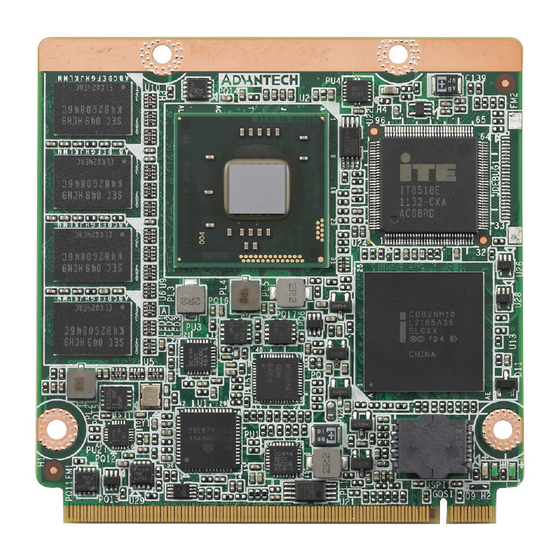
2.1.1 Board Connector The figures below indicate the main chips on the SOM-3565 Q7 Module. Please be aware of these positions when designing a customer carrier board to avoid mechani- cal upset and thermal solutions for the best thermal optimization. -
Page 13: Mechanical Drawings
Mechanical Drawings For more details about 2D/3D models, please check the Advantech COM support service website: http://www.advantech.com. Figure 2.3 Board Mechanical Drawing - Front Figure 2.4 Board Mechanical Drawing - Back SOM-3565 User Manual... - Page 14 SOM-3565 User Manual...
-
Page 15: Chapter 3 Bios Setup Information
Chapter BIOS Setup Information This chapter gives basic BIOS upgrade and setup information on the SOM-3565 CPU System on Module. Sections include: Safety Precautions BIOS Update Basic BIOS Setup... -
Page 16: Entering Setup
AMIBIOS has been integrated into many motherboards over the past decade. With the AMIBIOS Setup program, users can modify BIOS settings and control various system features. This chapter describes the basic navigation of the SOM-3565 BIOS setup screens. Figure 3.1 Setup Program Initial Screen AMI's BIOS ROM has a built-in setup program that allows users to modify the basic system configuration. -
Page 17: Main Setup
Date using the <Arrow> keys. Enter new values through the keyboard. Press the <Tab> key or the <Arrow> keys to move between fields. The date must be entered in MM/DD/YY format. The time must be entered in HH:MM:SS format. SOM-3565 User Manual... -
Page 18: Advanced Bios Features Setup
Advanced BIOS Features Setup Select the Advanced tab from the SOM-3565 setup screen to enter the Advanced BIOS Setup screen. Users can select any item in the left frame of the screen, such as CPU Configuration, to go to the sub menu for that item. Users can display an Advanced BIOS Setup option by highlighting it using the <Arrow>... -
Page 19: Advantech Bios Update V1.3
3.3.1 Advantech Bios Update V1.3 Figure 3.4 Advantech Bios Update V1.3 Advantech Bios Update V1.3 Press [Enter] to perform BIOS update. Please put new bios UPDATE.BIN in disk(FS0). SOM-3565 User Manual... -
Page 20: Acpi Settings
This item allows users to enable or disable hibernation. ACPI Sleep State This item allows users to set the ACPI sleep state. Lock Legacy Resources This item allows users to lock legacy device resources. S3 Video Repost Enable or Disable S3 Video Repost. SOM-3565 User Manual... -
Page 21: Cpu Configuration
This item allows users to enable or disable Intel Hyper Threading technology. Limit CPUID Maximum This item allows users to limit the maximum value of CPUID. Execute Disable Bit This item allows users to enable or disable the No-Execution page Protection tech- nology. SOM-3565 User Manual... -
Page 22: Sata Configuration
3.3.4 SATA Configuration Figure 3.7 SATA Configuration SATA Controller(s) This item allows users to enable or disable the SATA controller(s). SATA Mode Selection This item allows users to select mode of SATA controller(s). SOM-3565 User Manual... -
Page 23: Intel Fast Flash Standy
3.3.5 Intel Fast Flash Standy Figure 3.8 Intel Fast Flash Standy iFFS Support Enable or disable IFFS function. SOM-3565 User Manual... -
Page 24: Usb Configuration
Set maximum time the device will take before it properly reports itself to the Host Controller. 'Auto' uses default value: for a Root port it is 100 ms, for a Hub port the delay is taken from Hub descriptor. SOM-3565 User Manual... -
Page 25: Embedded Controller Configuration
This item allows users to set the value of CPU shutdown temperature. EC iManager Smart FAN This item allows users to enable or disable smart FAN feature. Backlight Function This item allows users to set backlight enable polarity. SOM-3565 User Manual... -
Page 26: Superio Configuration
Serial Port 0 Configuration This item allows users to configure serial port 0. Serial Port 1 Configuration This item allows users to configure serial port 1. Parallel Port Configuration This item allows users to configure the parallel port. SOM-3565 User Manual... -
Page 27: Serial Port Console Redirection
Both computers should have the same or compatible settings. Console Redirection (EMS) Console Redirection Enable or Disable. Console Redirection Settings This item allows users to enable or disable console redirection for Microsoft Windows Emergency Management Services (EMS). SOM-3565 User Manual... -
Page 28: Ppm Configuration
This item allows users to enable or disable CPU C-state support. Chipset Select the Chipset tab from the SOM-3565 setup screen to enter the Chipset BIOS Setup screen. You can display a Chipset BIOS Setup option by highlighting it using the <Arrow>... -
Page 29: Intel Igd Configuration
Figure 3.14 Chipset Setup 3.4.1 Intel IGD Configuration Figure 3.15 Intel IGD Configuration Intel IGD Configuration Config Intel IGD Settings. SOM-3565 User Manual... - Page 30 Select LCD panel used by Internal Graphics Device by selecting the appropriate setup item. Panel Scaling Select the LCD panel scaling option used by the Internal Graphics Device. Fixed Graphics Memory Size Configure Fixed Graphics Memory Size Backlight Control Support Backlight Control Configuration SOM-3565 User Manual...
- Page 31 High Precision Timer Enable or Disable the High Precision Event Timer. SLP_S4 Assertion Width Select a minimum assertion width of the SLP_S4# signal Restore AC Power Loss Select AC power state when power is re-applied after a power failure. SOM-3565 User Manual...
- Page 32 Enable or disable PCIE LAN to wake the system. SMBus Controller Enable or Disable OnChip SMBus Controller. SIRQ Logic Enable or Disable SIRQ logic. SIRQ Mode Set SIRQ mode. Debug Port 80 Show Debug Port 80 from PCI or LPC SOM-3565 User Manual...
- Page 33 PCI Express Hot Plug Enable/Disable. Extra Bus Reserved Extra Bus Reserved (0-7) for bridges behind this Root Bridge. Reserved Memory Reserved Memory and Prefetchable Memory (1-20MB) Range for this Root Bridge. Reserved I/O Reserved I/O (4K/8K/12K/16K/20K) Range for this Root Bridge. SOM-3565 User Manual...
- Page 34 PCI Express Hot Plug Enable/Disable. Extra Bus Reserved Extra Bus Reserved (0-7) for bridges behind this Root Bridge. Reserved Memory Reserved Memory and Prefetchable Memory (1-20MB) Range for this Root Bridge. Reserved I/O Reserved I/O (4K/8K/12K/16K/20K) Range for this Root Bridge. SOM-3565 User Manual...
- Page 35 PCI Express Hot Plug Enable/Disable. Extra Bus Reserved Extra Bus Reserved (0-7) for bridges behind this Root Bridge. Reserved Memory Reserved Memory and Prefetchable Memory (1-20MB) Range for this Root Bridge. Reserved I/O Reserved I/O (4K/8K/12K/16K/20K) Range for this Root Bridge. SOM-3565 User Manual...
-
Page 36: Boot Settings
Enabled, an OEM Logo is shown instead of POST messages. Option ROM Message Set display mode for option ROM. Interrupt 19 Capture This item allows option ROMs to trap interrupt 19. Boot This item allows users to set boot device priority. SOM-3565 User Manual... -
Page 37: Security Setup
Security Setup Figure 3.23 Password Configuration Select Security Setup from the SOM-3565 Setup main BIOS setup menu. All Security Setup options, such as password selection is described in this section. To access the sub menu for the following items, select the item and press <Enter>: Change Administrator / User Password: Select this option and press <ENTER>... -
Page 38: Save & Exit
Select this option to quit Setup without making any permanent changes to the system configuration and reboot the computer. 3.7.5 Save Changes When users have completed system configuration, select this option to save changes without exit BIOS setup menu. SOM-3565 User Manual... -
Page 39: Discard Changes
3.7.7 Restore Defaults The SOM-3565 automatically configures all setup items to optimal settings when users select this option. Optimal Defaults are designed for maximum system perfor- mance, but may not work best for all computer applications. In particular, do not use the Optimal Defaults if the users computer is experiencing system configuration prob- lems. - Page 40 SOM-3565 User Manual...
-
Page 41: S/W Introduction & Installation
Chapter S/W Introduction & Installation Sections include: S/W Introduction Driver Installation Advantech iManager... -
Page 42: S/W Introduction
It makes these embedded features easier to integrate, speed up develop- ing schedule, and provide the customer’s software continuity while upgrade hard- ware. More detail of how to use the APIs and utilities, please refer to Advantech iManager 2.0 Software API User Manual. -
Page 43: Advantech Software Utilities
Backlight Throttling Advantech Software Utilities Advantech also provides value-add utilities to make it easier for our customer to cre- ate their own unique and innovative systems. For more details about how to get and use these utilities, please contact Advantech. - Page 44 SOM-3565 User Manual...
-
Page 45: Appendix A Watchdog Timer
Appendix Watchdog Timer This appendix gives you the infor- mation about the watchdog timer programming on the SOM-3565 CPU System on Module. Sections include: Watchdog Timer Programming... -
Page 46: Programming The Watchdog Timer
Programming the Watchdog Timer Trigger Event Note IRQ7, 9, 11 (default disable) IRQ can be set in BIOS Power button event Power Off Support H/W Restart Support External WDT For details, please refer to iManager & Software API User Manual. SOM-3565 User Manual... -
Page 47: Appendix B Programming Gpio
Appendix Programming GPIO This Appendix gives the illustra- tion of the General Purpose Input and Output pin setting. Sections include: System I/O ports... -
Page 48: Gpio Register
GPIO Register GPIO Byte Mapping H/W Pin Name BIT0 GPO0 BIT1 GPO1 BIT2 GPO2 BIT3 GPO3 BIT4 GPO0 BIT5 GPO1 BIT6 GPO2 BIT7 GPO3 For details, please refer to iManager & Software API User Manual. SOM-3565 User Manual... -
Page 49: Appendix C System Assignments
Appendix System Assignments This appendix gives you the infor- mation about the system resource allocation on the SOM-3565 CPU System on Module. Sections include: System I/O ports DMA Channel Assignments Interrupt Assignments 1st MB Memory Map... -
Page 50: System I/O Port
03F6 - 03F6 Primary IDE Channel 03F8 - 03FF Communications Port (COM1) 0400 - 041F Intel(R) ICH8 Family SMBus Controller – 283E 04D0 - 04D1 Motherboard resources 0500 - 053F Motherboard resources 0800 - 087F Motherboard resources SOM-3565 User Manual... -
Page 51: Dma Channel Assignments
Intel ICH8M 3 port Serial ATA Storage Controller - 2828 FFA0 – FFAF Intel ICH8M Ultra ATA Storage Controller - 2850 DMA Channel Assignments Table C.2: DMA Channel Assignments Channel Function Available Available Available Available Direct memory access controller Available Available Available SOM-3565 User Manual... -
Page 52: Interrupt Assignments
Intel(R) 82567V-3 Gigabit Network Connection* IRQ 23 Intel ICH8 Family USB Universal Host Controller - 2830* IRQ 23 Intel ICH8 Family USB2 Universal Host Controller - 2836* *USB and Ethernet IRQ is automatically set by the system. SOM-3565 User Manual... -
Page 53: 1St Mb Memory Map
Motherboard resources FED90000 - FED93FFF System board FED90000 - FFFFFFFF System board FEE00000 - FEE00FFF Motherboard resources FFB00000 - FFBFFFFF Intel 82802 Firmware Hub Device FFC00000 - FFEFFFFF Motherboard resources FFF00000 - FFFFFFFF Intel 82802 Firmware Hub Device SOM-3565 User Manual... - Page 54 No part of this publication may be reproduced in any form or by any means, electronic, photocopying, recording or otherwise, without prior written permis- sion of the publisher. All brand and product names are trademarks or registered trademarks of their respective companies. © Advantech Co., Ltd. 2013...
- Page 55 Mouser Electronics Authorized Distributor Click to View Pricing, Inventory, Delivery & Lifecycle Information: Advantech SOM-3565M0-S6A1E SOM-3565M0Z2-S6A1E SOM-3565M0Z-S6A1E SOM-3565M4-S6A1E...
Need help?
Do you have a question about the SOM-3565 and is the answer not in the manual?
Questions and answers