Table of Contents
Advertisement
Quick Links
Advertisement
Table of Contents

Related Manuals for Advantech SOM-6883


Summary of Contents for Advantech SOM-6883
- Page 1 User Manual SOM-6883 CPU Computer on Module...
- Page 2 No part of this manual may be reproduced, copied, translated or transmitted in any form or by any means without the prior written permission of Advantech Co., Ltd. Information provided in this manual is intended to be accurate and reliable. How- ever, Advantech Co., Ltd.
- Page 3 This product has passed the CE test for environmental specifications when shielded cables are used for external wiring. We recommend the use of shielded cables. This type of cable is available from Advantech. Please contact your local supplier for ordering information.
- Page 4 Document Feedback To assist us in making improvements to this manual, we welcome comments and constructive criticism. Please send all such in writing to: support@advantech.com Safety Precaution — Static Electricity Follow these simple precautions to protect yourself from harm and the products from...
- Page 5 The sound pressure level at the operator's position according to IEC 704-1:1982 is no more than 70 dB (A). DISCLAIMER: This set of instructions is given according to IEC 704-1. Advantech disclaims all responsibility for the accuracy of any statements contained herein.
- Page 6 SOM-6883 User Manual...
-
Page 7: Table Of Contents
Power Management..............9 1.3.10 Environment................10 1.3.11 MTBF ..................10 1.3.12 OS Support (SW Chapter Duplicate) .......... 10 1.3.13 Advantech iManager ..............10 1.3.14 Power Consumption..............11 1.3.15 Performance ................11 1.3.16 Selection Guide w/P/N ..............12 1.3.17 Packing list.................. 12 1.3.18 Development Board .............. - Page 8 Figure 3.48 LCD Panel Type ............55 Figure 3.49 LVDS Clock Spreading Settings......56 Figure 3.50 LVDS Swing Level Settings........56 3.5.2 PCH-IO Configuration..............57 Figure 3.51 PCH-IO Configuration ..........57 Figure 3.52 PCI Express Configuration ........58 SOM-6883 User Manual viii...
- Page 9 Windows Driver Setup ..............70 4.2.2 Other OS..................70 Advantech iManager ................71 Appendix A Pin Assignment .........73 SOM-6883 Type 6 Pin Assignment............74 Appendix B Watchdog Timer ........79 Programming the Watchdog Timer ............80 Appendix C Programming GPIO ......81 GPIO Register..................
- Page 10 SOM-6883 User Manual...
-
Page 11: Chapter 1 General Information
Chapter General Information This chapter details the SOM-6883 CPU Computer on Module back- ground information. Sections include: Introduction Functional Block Diagram Product Specifications... -
Page 12: Introduction
1.2V power design, up to 16GB memory down, and 32GB SO-DIMM. In addition, SOM-6883 augments memory capacity configuration via an i7-1185G7E SKU upgrade to quad-core. SOM-6883 further provides super speed I/O technology — such as 2.5Gbase-T TSN LAN, PCIe Gen 4, and USB 3.2 Gen 2. - Page 13 Serial Presence Detect – refers to serial EEPROM on DRAMs that has DRAM Module configuration information Trusted Platform Module, chip to enhance the security features of a computer system UEFI Unified Extensible Firmware Interface Watchdog Timer SOM-6883 User Manual...
-
Page 14: Functional Block Diagram
Functional Block Diagram SOM-6883 User Manual... -
Page 15: Product Specifications
Speaker Out External BIOS ROM Support Power Button Support Power Good VCC_5V_SBY Contacts Sleep Thermal Protection Lid Input Battery Low Alarm Suspend/Wake Signals Fan PWM / Tachometer Trusted Platform Modules Display Digital Display Interfaces 1 - 3 SOM-6883 User Manual... -
Page 16: Processor System
4.4GHz i5-1145G7E Iris® Xe Graphics 1.5GHz 4.1GHz i3-1115G4E Iris® Xe Graphics 2.2GHz 3.9GHz Celeron® 6305E Intel® UHD Graphics 1.8GHz i7-1185GRE Iris® Xe Graphics 1.8GHz 4.4GHz i5-1145GRE Iris® Xe Graphics 1.5GHz 4.1GHz i3-1115GRE Intel® UHD Graphics 2.2GHz 3.9GHz SOM-6883 User Manual... -
Page 17: Expansion Interface
1.3.8.3 USB 3.0 (3.1 Gen 2) and USB 2.0 SOM-6883 supports 4 x USB 3.2 Gen 2 (10 Gbps) ports and 8 x USB 2.0 (480 Mbps) ports. These are backwards compatible with USB 1.x. USB 3.1 supports LPM (U0, U1, U2, and U3) manageability to conserve power. - Page 18 SPI_CS0# to Carrier Board, SPI_CS1# to Module SPI_CS0# to Module, SPI_CS1# to Carrier Board Notice: We recommend going to the BIOS setup menu and loading the default set- tings during the first boot up if the system COMS are cleared. SOM-6883 User Manual...
-
Page 19: Power Management
FPGAs or other configurable devices. 1.3.9.3 Power Sequence Adheres to PICMG COM Express R3.0 specifications. 1.3.9.4 Wake Event Diverse wake-up event support allows users to apply the solution to different scenar- ios: Wake-on-LAN (WOL): Wake to S0 from S3/S4/S5 SOM-6883 User Manual... -
Page 20: Environment
1.3.9.5 Advantech S5 ECO Mode (Deep Sleep Mode) Advantech iManager features a mechanism that allows the system to enter a very low suspended power mode, or “S5 ECO mode”. In this mode, the module will cut power entering the chipset — including suspend and active power — and keep an on-module controller active. -
Page 21: Power Consumption
Maximum load mode: Running programs – Idle mode: DUT power management off and not running any program OS: Windows 10 Enterprise 1.3.15 Performance Please refer to the “Advantech COM Performance and Power Consumption Table” for reference performance and/or benchmark data. SOM-6883 User Manual... -
Page 22: Selection Guide W/P/N
COMe Devel.Board COMe R3.0 Type6 pin-out 1.3.19 Optional Accessories Part No. Description 1970004870T001 Semi-Cooler 95 x 95 x 33 mm/3.7 x 3.7 x 1.29 in with 12V Fan 1970004871T001 QFCS 95 x 95 x 26 mm/3.7 x 3.7 x 1.02 in SOM-6883 User Manual... -
Page 23: Pin Description
1.3.20 Pin Description Advantech provides checklists for schematic design and layout routing. The sche- matic checklist details pin electrical properties and connections for different scenar- ios. The checklist also specifies layout constraints and recommendations for trace length and impedance. Please contact Advantech for further support. - Page 24 SOM-6883 User Manual...
-
Page 25: Chapter 2 Mechanical Information
Chapter Mechanical Information This chapter details SOM-6883 CPU Computer on Module mechanical information Sections include: Board Information Mechanical Drawing Assembly Drawing... -
Page 26: Board Information
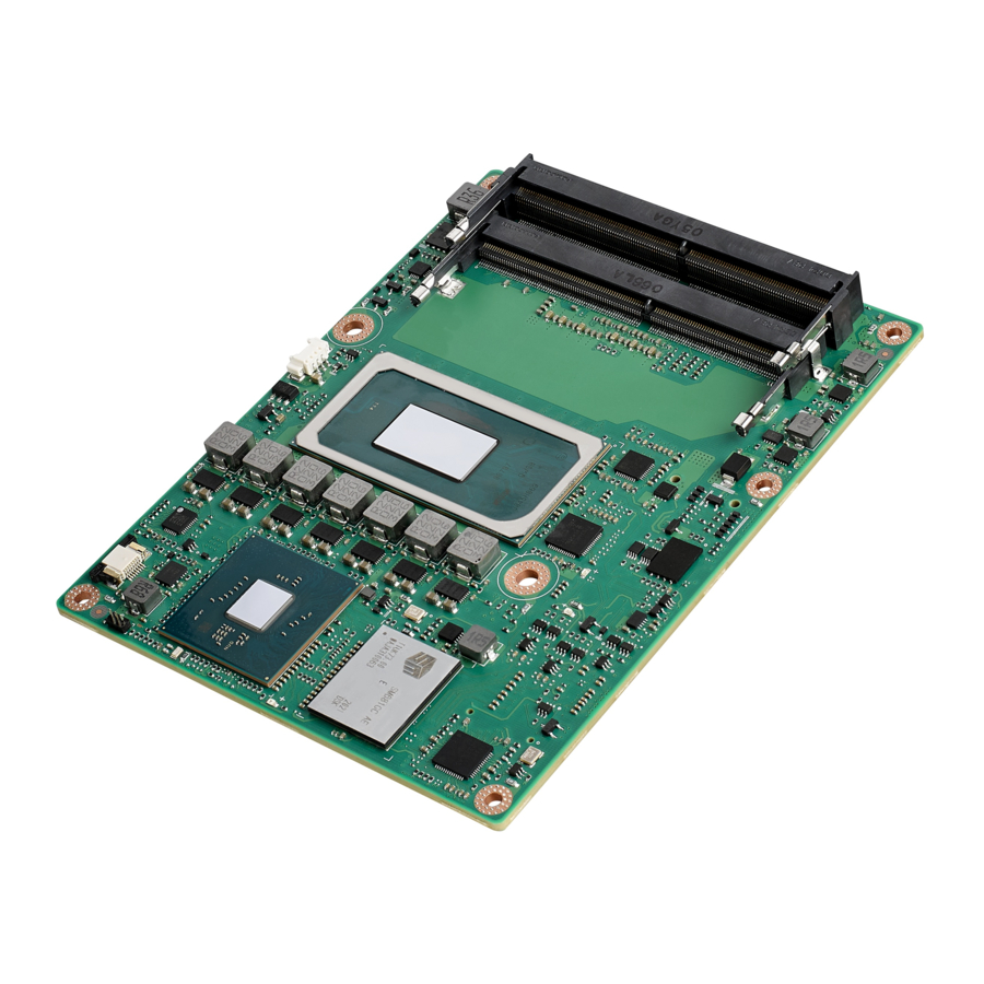
Board Information The figures below show the main chips on the SOM-6883 Computer-on-Module. To avoid mechanical damage and improve heat dissipation performance — please keep these positions in mind when designing carrier boards. Figure 2.1 Board Chips Diagram – Front Figure 2.2 Board Chips Diagram –... -
Page 27: Connector List
Wafter 1.25 mm 3P 90D(M)DIP 53261-0371 Pin Name Fan Tacho-Input Fan Out Mechanical Diagram For further details or information regarding 2D/3D models, please visit the Advantech COM support service website http://com.advantech.com. Figure 2.3 Board Mechanical Drawing – Front SOM-6883 User Manual... - Page 28 Figure 2.4 Board Mechanical Diagram – Rear Figure 2.5 Board Mechanical Diagram – Side SOM-6883 User Manual...
-
Page 29: Exploded Diagram
Exploded Diagram These figures demonstrate the thermal module assembly order — from COM module to carrier board. Figure 2.6 Assembly Diagram There are 4 x reserved screw holes on SOM-6883 used in heat spreader assembly. SOM-6883 User Manual... -
Page 30: Assembly Diagram
Assembly Diagram Please consider the CPU and chip height tolerance when designing your thermal solution. Figure 2.7 10 TGL-UP3 4C Height and Tolerance Diagram (For all other SKUs please contact to Advantech sales or FAE for further details.) SOM-6883 User Manual... -
Page 31: Chapter 3 Ami Bios
Chapter AMI BIOS This chapter details SOM-6883 BIOS setup information. Sections include: Introduction Entering Setup Hot/operation Key Exit BIOS Setup Utility... -
Page 32: Introduction
Figure 3.1 Setup Program Initial Screen AMI's BIOS ROM has a built-in Setup program that allows users to modify the basic system configuration. This information is stored in flash ROM so it retains the Setup information when the power is turned off. SOM-6883 User Manual... -
Page 33: Entering Setup
System Date using the <Arrow> keys. Enter new values through the keyboard. Press the <Tab> key or the <Arrow> keys to move between fields. The date must be entered in MM/DD/YY format. The time must be entered in HH:MM:SS format. SOM-6883 User Manual... -
Page 34: Advanced Bios Features Setup
Advanced BIOS Features Setup Select the Advanced tab from the SOM-6883 setup screen to enter the Advanced BIOS Setup screen. Users can select any item in the left frame of the screen, such as CPU Configuration, to go to the sub menu for that item. Users can display an Advanced BIOS Setup option by highlighting it using the <Arrow>... -
Page 35: Rc Acpi Settings
3.4.1 RC ACPI Settings Figure 3.4 RC ACPI Settings SOM-6883 User Manual... -
Page 36: Cpu Configuration
3.4.2 CPU Configuration Figure 3.5 CPU Configuration_1 Intel (VMX) Virtualization Technology Active Processor Core SOM-6883 User Manual... - Page 37 Figure 3.6 Active Processor Core Setting Hyper-Threading MonitorMWait Intel Trusted Execution Technology SOM-6883 User Manual...
- Page 38 3.4.3 Power & Performance Figure 3.7 Power & Performance CPU- Power Management Control GT- Power Management Control SOM-6883 User Manual...
- Page 39 Figure 3.8 CPU- Power Management Control Boot performance mode ® Intel SpeedStep™ Turbo Mode Config TDP Configurations SOM-6883 User Manual...
- Page 40 Figure 3.9 Configurable TDP Boot Mode Figure 3.10 ConfigTDP Turbo Activation Ratio SOM-6883 User Manual...
- Page 41 GT- Power Management Control Figure 3.11 GT- Power Management Control RC6 (Render Standby) Check to enable render standby support. SOM-6883 User Manual...
- Page 42 3.4.4 PCH-FW Configuration Figure 3.12 PCH-FW Configuration ME Firmware – Version – Mode – – Status 1 – Status 2 ME State ME Unconfig on RTC Clear Firmware Update Configuration SOM-6883 User Manual...
- Page 43 Figure 3.13 Firmware Update Configuration 3.4.5 Trusted Computing Figure 3.14 Trusted Computing SOM-6883 User Manual...
- Page 44 3.4.6 ACPI Settings Figure 3.15 ACPI Settings Enable ACPI Auto Configuration Enable Hibernation ACPI Sleep State S3 Video Repost SOM-6883 User Manual...
- Page 45 Smart Fan – COM Module Smart Fan – Carrier Board. Backlight Enable Polarity Brightness Mode Selection Brightness PWM Polarity Power Saving Mode Serial Port 1 Configuration Serial Port 2 Configuration Hardware Monitor SOM-6883 User Manual...
- Page 46 Serial Port 1 Configuration Figure 3.17 Serial Port 1 Configurations Serial Port Change Settings SOM-6883 User Manual...
- Page 47 Serial Port 2 Configuration Figure 3.18 Serial Port 2 Configurations Serial Port Change Settings SOM-6883 User Manual...
- Page 48 Hardware Monitor Figure 3.19 Hardware Monitor 3.4.8 Serial Port Console Redirection Figure 3.20 Serial Port Console Redirection COM1 Console Redirection SOM-6883 User Manual...
- Page 49 Figure 3.21 Terminal Type Settings Figure 3.22 Terminal Type Settings SOM-6883 User Manual...
- Page 50 Figure 3.23 Data Bits Settings Figure 3.24 Parity Settings SOM-6883 User Manual...
- Page 51 Figure 3.25 Stop Bits Settings Figure 3.26 Flow Control Settings SOM-6883 User Manual...
- Page 52 Figure 3.27 Putty KeyPad Settings COM2 Console Redirection COM3 Console Redirection COM4 Console Redirection Legacy Console Redirection Settings Console Redirection SOM-6883 User Manual...
- Page 53 Enables Legacy USB support. Auto option disables legacy support if no USB devices are connected. Disable option will keep USB devices available only for EFI applications: – XHCI Hand-off – USB Mass Storage Driver Support – USB transfer time-out SOM-6883 User Manual...
- Page 54 Figure 3.29 USB Transfer Time-out Settings Device reset time-out Device power-up delay Figure 3.30 Device Power-up Delay Settings SOM-6883 User Manual...
- Page 55 3.4.10 NVMe Configuration Figure 3.31 NVMe Configuration SOM-6883 User Manual...
- Page 56 3.4.11 Network Stack Configuration Figure 3.32 Network Stack Configuration Figure 3.33 Network Stack Configuration Settings SOM-6883 User Manual...
- Page 57 Chipset Settings Select the chipset tab from the SOM-6883 setup screen to enter the chipset BIOS Setup screen. You can display a chipset BIOS setup option by highlighting it using the <Arrow> keys. All Plug and Play BIOS setup options are described in this section.
- Page 58 3.5.1 System Agent (SA) Configuration Figure 3.35 System Agent (SA) Configuration Memory Configuration Graphics Configuration VT-d SOM-6883 User Manual...
- Page 59 Memory Configuration Figure 3.36 Memory Configuration Graphics Configuration Figure 3.37 Graphics Configuration SOM-6883 User Manual...
- Page 60 Primary Display Figure 3.38 Primary Display Internal Graphics Figure 3.39 Internal Graphics Settings SOM-6883 User Manual...
- Page 61 GTT Size Figure 3.40 GTT Size Settings Aperture Size Figure 3.41 Aperture Size Settings SOM-6883 User Manual...
- Page 62 DVMT Pre-Allocated Figure 3.42 DVMT Pre-Allocated Settings DVMT Toal Gfx Mem Figure 3.43 DVMT Toal Gfx Mem Settings SOM-6883 User Manual...
- Page 63 PM Support Figure 3.44 PM Support Settings PAVP Enable PAVP Enable LCD Control SOM-6883 User Manual...
- Page 64 Figure 3.45 LCD Control Setting NXP non-EDID Support Color depth and packing format Figure 3.46 Color Depth and Packing Format Settings SOM-6883 User Manual...
- Page 65 Dual LVDS mode Figure 3.47 Dual LVDS Mode Settings LCD Panel Type Figure 3.48 LCD Panel Type SOM-6883 User Manual...
- Page 66 LVDS clock spreading Figure 3.49 LVDS Clock Spreading Settings LVDS swing level Figure 3.50 LVDS Swing Level Settings SOM-6883 User Manual...
- Page 67 USB Configuration Security Configuration HD Audio Configuration SerialIo Configuration SCS Configuration – PCH LAN Controller – Wake on LAN Enable – Serial IRQ Mode – State After G3 – PCIe Pll SSC SOM-6883 User Manual...
- Page 68 PCI Express Root Port 2 settings. PCI Express Root Port 3 PCI Express Root Port 3 settings. PCI Express Root Port 4 PCI Express Root Port 4 settings. PCI Express Root Port 5 PCI Express Root Port 2 settings. SOM-6883 User Manual...
- Page 69 PCI Express Root Port 0 Configuration Figure 3.53 PCI Express Root Port 0 Configuration PCI Express Root Port 0 ASPM – Hot Plug PCIe Speed SOM-6883 User Manual...
- Page 70 Indicates the maximum speed the SATA controller can support. Port 0 Enable or Disable SATA port. – SATA Device Type – SATA Port 0 DevSlp Port 1 Enable or Disable SATA port. SATA Device Type SATA Port 0 DevSlp SOM-6883 User Manual...
- Page 71 USB Configuration Figure 3.55 USB Configuration XHCI Disable Compliance Mode Options to disable Compliance Mode. Default is False to not disable Compliance Mode. Set TRUE to disable Compliance Mode. SOM-6883 User Manual...
- Page 72 Security Configuration Figure 3.56 Security Configuration Settings SOM-6883 User Manual...
- Page 73 Figure 3.57 HD Audio Configuration HD Audio Control Detection of the HD-Audio device. – Disabled= HDA will be unconditionally disabled – Enabled= HDA will be unconditionally enabled – Auto= HDA will be enabled if present, disabled otherwise SOM-6883 User Manual...
- Page 74 Security Configuration Figure 3.58 Security Configuration Settings RTC Memory Lock BIOS Lock SOM-6883 User Manual...
- Page 75 Serial I/O Configuration Figure 3.59 Serial I/O Configuration Settings SOM-6883 User Manual...
-
Page 76: Security Settings
Security Settings Figure 3.60 Security Setup Select Security Setup from the SOM-6883 Setup main BIOS setup menu. All Security Setup options, such as password protection, are described in this section. To access the sub menu for the following items, select the item and press <Enter>: Change Administrator/User Password: Select this option and press <ENTER>... -
Page 77: Boot Settings
3.5.4 Boot Settings Figure 3.61 Security Setup Setup Prompt Timeout Bootup NumLock State Quiet Boot Boot option#1 Fast Boot SOM-6883 User Manual... -
Page 78: Save & Exit
Save Changes and Exit Discard Changes and Exit Save Changes and Reset Discard Changes and Reset Save Changes Discard Changes Restore Defaults Save User Defaults Restore User Defaults SOM-6883 User Manual... -
Page 79: Chapter 4 S/W Introduction And Installation
Chapter S/W Introduction and Installation S/W Introduction Driver Installation Advantech iManager... -
Page 80: S/W Introduction
4.2.1 Windows Driver Setup SOM-6883 supports Windows* 10 Enterprise. To install the drivers on a windows- based operation system, please connect to internet and browse the website http:// support.advantech.com.tw and download the drivers that you want to install and fol- low Driver Setup instructions to complete the installation. -
Page 81: Advantech Imanager
Advantech iManager Advantech’s platforms come equipped with iManager, a micro controller that provides embedded features for system integrators. Embedded features have been moved from the OS/BIOS level to the board level to increase reliability and simplify integra- tion. iManager runs whether the operating system is running or not; it can count the boot times and running hours of the device, monitor device health, and provide an advanced watchdog to handle errors. - Page 82 SOM-6883 User Manual...
-
Page 83: Appendix A Pin Assignment
Appendix Pin Assignment This appendix details the SOM- 6883 hardware pin assignment Sections include: SOM-6883 Type 6 Pin Assign- ment... -
Page 84: Som-6883 Type 6 Pin Assignment
SOM-6883 Type 6 Pin Assignment This section surveys SOM-6883’s pin assignment on COM Express connector. It is compliant with COMR.0 R3.0 Type 6 pin-out definitions. Contact Advantech to acquire further pin usage details or a design reference. Likewise, please contact Advantech for a design guide, checklist, reference schematic, and other hardware/ software support. - Page 85 LVDS_A0- LVDS_B0- LVDS_A1+ LVDS_B1+ LVDS_A1- LVDS_B1- LVDS_A2+ LVDS_B2+ LVDS_A2- LVDS_B2- LVDS_VDD_EN LVDS_B3+ LVDS_A3+ LVDS_B3- LVDS_A3- LVDS_BKLT_EN GND (FIXED) GND (FIXED) LVDS_A_CK+ LVDS_B_CK+ LVDS_A_CK- LVDS_B_CK- LVDS_I2C_CK LVDS_BKLT_CTRL LVDS_I2C_DAT VCC_5V_SBY GPI3 VCC_5V_SBY N/A (*Note) VCC_5V_SBY eDP_HPD VCC_5V_SBY PCIE_CLK_REF+ BIOS_DIS1# SOM-6883 User Manual...
- Page 86 A107 VCC_12V B107 VCC_12V A108 VCC_12V B108 VCC_12V A109 VCC_12V B109 VCC_12V A110 GND (FIXED) B110 GND (FIXED) SOM-6883 Row C, D GND (FIXED) GND (FIXED) USB_SSRX0- USB_SSTX0- USB_SSRX0+ USB_SSTX0+ USB_SSRX1- USB_SSTX1- USB_SSRX1+ USB_SSTX1+ USB_SSRX2- USB_SSTX2- USB_SSRX2+ USB_SSTX2+ GND (FIXED)
- Page 87 GND (FIXED) DDI2_CTRLCLK_AUX+ DDI1_PAIR2+ DDI2_CTRLDATA_AUX- DDI1_PAIR2- DDI2_DDC_AUX_SEL DDI1_DDC_AUX_SEL DDI1_PAIR3+ DDI1_PAIR3- DDI2_PAIR0+ DDI2_PAIR0- GND (FIXED) GND (FIXED) DDI2_PAIR1+ DDI2_PAIR1- DDI2_HPD DDI2_PAIR2+ DDI2_PAIR2- DDI2_PAIR3+ DDI2_PAIR3- GND (FIXED) GND (FIXED) TYPE2# (GND) GND (FIXED) GND (FIXED) RAPID_SHUTDOWN GND (FIXED) GND (FIXED) SOM-6883 User Manual...
- Page 88 C106 VCC_12V D106 VCC_12V C107 VCC_12V D107 VCC_12V C108 VCC_12V D108 VCC_12V C109 VCC_12V D109 VCC_12V C110 GND (FIXED) D110 GND (FIXED) *Note: A86 could be an optional pin reserved for SD_PWR_EN. Please contact FAE for details. SOM-6883 User Manual...
-
Page 89: Appendix B Watchdog Timer
Appendix Watchdog Timer This appendix details watchdog timer programming information for the SOM-6883 CPU System on Module. Sections include: Watchdog Timer Programming... -
Page 90: Programming The Watchdog Timer
** WDT new driver support automatically selects available IRQ numbers from BIOS, and then sets the EC.This is only supported in Windows 10. Other OS use IRQ numbers from the BIOS settings. For details, please refer to the iManager & Software API User Manual. SOM-6883 User Manual... -
Page 91: Appendix C Programming Gpio
Appendix Programming GPIO This appendix diagrams General Purpose Input and Output pin set- tings. Sections include: System I/O ports... -
Page 92: Gpio Register
H/W Pin Name BIT0 GPI 0 BIT1 GPI 1 BIT2 GPI 2 BIT3 GPI 3 BIT4 GPO 0 BIT5 GPO 1 BIT6 GPO 2 BIT7 GPO 3 For details, please refer to iManager & Software API User Manual. SOM-6883 User Manual... -
Page 93: Appendix D System Assignments
Appendix System Assignments This appendix details the SOM- 6883 system resource allocation. Sections include: System I/O ports DMA Channel Assignments Interrupt Assignments 1 MB Memory Map... -
Page 94: System I/O Ports
00AC-00AD Programmable interrupt controller 00B0-00B1 Programmable interrupt controller 00B4-00B5 Programmable interrupt controller 00B8-00B9 Programmable interrupt controller 00BC-00BD Programmable interrupt controller 04D0-04D1 Programmable interrupt controller 1854-1857 Motherboard resources 3090-3097 Standard SATA AHCI Controller 3080-3083 Standard SATA AHCI Controller SOM-6883 User Manual... -
Page 95: Interrupt Assignments
PCI Express Root Port IRQ 4294967274 Intel® GNA Scoring Accelerator module 1st MB Memory Map Table D.3: 1st MB Memory Map Addr. Range (Hex) Device 0xFEDC0000-0xFEDC7FFF Motherboard resources 0xFEDA0000-0xFEDA0FFF Motherboard resources 0xFEDA1000-0xFEDA1FFF Motherboard resources 0xC0000000-0xCFFFFFFF Motherboard resources 0xFED20000-0xFED7FFFF Motherboard resources SOM-6883 User Manual... - Page 96 Trusted Platform Module 2.0 0xFFEFA000-0xFFEFAFFF Intel® Management Engine Interface 0x0000-0xFFFFFF Intel® Iris® Xe Graphics 0x0000-0xFFFFFFF Intel® Iris® Xe Graphics 0xFFEFB000-0xFFEFBFFF Intel® GNA Scoring Accelerator module 0xFFEFC000-0xFFEFFFFF High Definition Audio Controller 0xFFF00000-0xFFFFFFFF High Definition Audio Controller 0x1128000-0x11280FF Intel® SMBus - A0A3 SOM-6883 User Manual...
- Page 97 SOM-6883 User Manual...
- Page 98 No part of this publication may be reproduced in any form or by any means, electronic, photocopying, recording or otherwise, without prior written permis- sion from the publisher. All brand and product names are trademarks or registered trademarks of their respective companies. © Advantech Co., Ltd. 2021...
Need help?
Do you have a question about the SOM-6883 and is the answer not in the manual?
Questions and answers