
Related Manuals for Queclink GV75


Summary of Contents for Queclink GV75
- Page 1 GV75 User Manual GV75 User Manual GSM/GPRS/GPS Tracker TRACGV75UM001 Version: R1.03 TRACGV75UM0010...
- Page 2 TRACGV75UM001 General Notes Queclink offers this information as a service to its customers, to support application and engineering efforts that use the products designed by Queclink. The information provided is based upon requirements specifically provided to Queclink by the customers. Queclink has not undertaken any independent search for additional relevant information, including any information that may be in the customer’s possession.
-
Page 3: Table Of Contents
GV75 User Manual Contents Contents ..............................2 Table Index ............................3 Figure Index ............................4 0. Revision History ..........................5 1. Introduction ............................6 1.1. Reference ..........................6 1.2. Terms and Abbreviations ......................6 2. Product Overview ..........................7 2.1. Appearance ..........................7 2.2. - Page 4 TABLE 2: TERMS AND ABBREVIATIONS ....................6 TABLE 3: PARTS LIST ..........................7 TABLE 4: DESCRIPTION OF GV75 USER CABLE ..................8 TABLE 5: ELECTRICAL CHARACTERISTICS OF IGNITION DETECTION ............11 TABLE 6: ELECTRICAL CONDITIONS OF NEGATIVE TRIGGER INPUTS ............11 TABLE 7: ELECTRICAL CONDITIONS OF DIGITAL OUTPUTS ..............
-
Page 5: Figure Index
GV75 User Manual Figure Index FIGURE 1: EXAMPLE CONNECTION FOR NEGATIVE TRIGGER INPUTS ............ 11 FIGURE 2: THE EXAMPLE CONNECTION TO DRIVE A LED ............... 12 FIGURE 3: THE EXAMPLE CONNECTION TO DRIVE A RELAY ..............12 FIGURE 4: THE CONNECTION OF UART WITH FEMALE DB-9 ..............12 FIGURE 5: THE CONNECTION OF UART WITH EXTERNAL DEVICES ............ -
Page 6: Revision History
GV75 User Manual 0. Revision History Revision Date Author Description of Change 1.01 2016-01-07 BingoHuang Initial 1.02 2016-01-25 Abside Yu Add Safety Information 1.03 2016-04-15 Abside Yu Modify “Getting Start” and product appearance TRACGV75UM0015... -
Page 7: Introduction
GV75 User Manual 1. Introduction The GV75 is a compact waterproof GPS tracker designed for a wide variety of vehicle tracking applications. It has multiple I/O interfaces that can be used for monitoring or controlling external devices. Its built-in GPS receiver has superior sensitivity and fast time to first fix. Its quad band GPRS/GSM subsystem supports 850/900/1800/1900 MHz allowing the GV75's location to be monitored in real time or periodically tracked by a backend server and mobile devices. -
Page 8: Product Overview
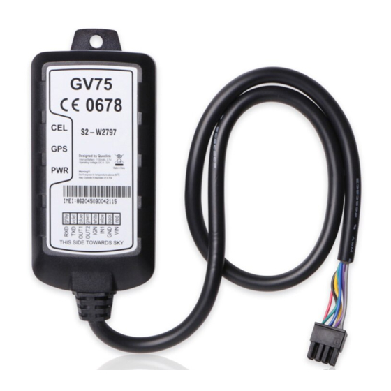
GV75 User Manual 2. Product Overview 2.1. Appearance Figure 1. Appearance of GV75 2.2. Parts List Name Picture GV75 Tracker 102mm*46mm*20.5mm GV75 Extend Cable USB-232 Cable(optional) 12V DC Supply(optional) GV75 Configuration Cable(optional) Table 3: Parts List TRACGV75UM0017... -
Page 9: Interface Definition
Digital input Digital input, negative trigger White Ignition Ignition input, positive trigger Green Digital output2 Digital output,low side 150mA max Blue Digital output1 Digital output,low side 150mA max with latch Violet Grey Table 4: Description of GV75 User Cable TRACGV75UM0018... -
Page 10: Getting Started
GV75 User Manual 3. Getting Started 3.1. Install a SIM Card Step 1: Remove the top cover. Step 2: Insert the SIMcard into the SIM card holder. Step 3: Place the top cover on the bottom cover, and tightenboth covers until they snap. -
Page 11: Switch On The Device
- Use external power to turn on. When the external power is removed,GV75 will switch to internal backup battery and keep on running. When internal backup battery is exhausted, GV75 will give a report and then turn off. 3.3. Power Connection The red wireis power wire and the black wire is ground wire. -
Page 12: Ignition Detection
3.5. Digital Input There is a negative trigger input on the GV75.For negative trigger input the electrical conditions are: Logical State... -
Page 13: Uart Interface
Table 7: Electrical Conditions of Digital Outputs Note: 1. The relay output can be latched by the software, so even if the GV75 is restarted or powered down in some cases, the relay output will not change. To use the latch function, the main power and backup battery should be connected. -
Page 14: Indicator Light Description
GV75 User Manual Figure 5: The Connection of UART with External Devices 3.8. Indicator Light Description Figure 6:GV75 LED Device Status LED Status Device is searching GSM network. Fast flashing (Note1) (Note3) Device has registered to GSM network. Slow flashing (Note4) SIM card needs pin code to unlock. -
Page 15: Troubleshooting And Safety Info
Please do not put the device in anoverheatedor too humid place, and avoid exposure to direct sunlight. Too high temperature will damage the device or even cause battery explosion. Please do not use GV75 on anairplane or near medical equipment. TRACGV75UM00114...
Need help?
Do you have a question about the GV75 and is the answer not in the manual?
Questions and answers