Table of Contents
Advertisement
Quick Links
Advertisement
Table of Contents

Related Manuals for Insportline Avalor ET


Summary of Contents for Insportline Avalor ET
- Page 1 USER MANUAL – EN IN 16187 Elliptical Trainer inSPORTline Avalor ET...
-
Page 2: Table Of Contents
CONTENTS SAFETY INSTRUCTIONS ........................3 EXPLODED DRAWINGS ........................4 PARTS LIST ............................6 PRODUCT DESCRIPTION ........................9 TECHNICAL SPECIFICATION ........................ 9 HARDWARE LIST ..........................10 ASSEMBLY INSTRUCTIONS ....................... 12 EXERCISING INSTRUCTIONS ......................15 CONSOLE OPERATION INSTRUCTION ..................... 16 LCD DISPLAY SCREEN ........................16 FUNCTION DESCRIPTION ....................... -
Page 3: Safety Instructions
SAFETY INSTRUCTIONS • Read this manual carefully before first using and keep it for future reference. • Assemble, use and maintain it only according to this manual and for intended purpose. • Never do any improper modification to avoid an injury. •... -
Page 4: Exploded Drawings
EXPLODED DRAWINGS... -
Page 6: Parts List
PARTS LIST Description Specification Qty. Basic frame Main frame Console fix frame Upper swing arm-left Upper swing arm-right Bottom swing arm-left Bottom swing arm-right Pedal group-left Pedal group-right Pedal connection leg-left Pedal connection leg-right Crank Tension wheel fixer Out cover-left Out cover-right Top cover-left Top cover-right... - Page 7 Pulley Feet pad Motor belt Console group Hand pulse top cover Magnet sensor fixer Sliding rail aluminium sheet 670x29.5x11.2 Ø6xØ20xt2.0 Flat washer Ø8.5xØ20xt1.5 Flat washer Ø8.2xØ25xt2.0 Flat washer Ø32xØ8.5xt2.0 Flat washer Ø10xØ22xt2.0 Flat washer Ø12.5xØ22xt2.0 Flat washer Ø10.5xR100xt2.0 Curved washer Ø8.5xR25xt2.0 Curved washer Ø8...
- Page 8 Allen cylinder head full thread bolt M12x105x15 Allen full thread bolt M6x20 Flat key 8x10x18 Tube cap BLF82/ø39xø30x27.5 Deep groove ball bearing 6201-ZZ Deep groove ball bearing 6004-ZZ Deep groove ball bearing 6005-ZZ Bushing E12/ø16xø12x6.3 Ø32x11.5 Tube cap Ø30xt.3.0x350 Foam 103x Ø26xM6x50 Hook Ø17x Ø8.5x47...
-
Page 9: Product Description
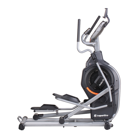
PRODUCT DESCRIPTION 1) Console 2) Main frame 3) Arm 4) Handlebar 5) Arm top 6) Air outlet 7) Pedal 8) Basic frame TECHNICAL SPECIFICATION Model No. Dimensions (unfolded) 1600x650x1770 mm Max. user weight 150 kg Speed ratio Inside magnet, two-way, ø450, 8 kg Flywheel Resistance level 1-24... -
Page 10: Hardware List
HARDWARE LIST Description Specification Qty. Allen cylinder head half-thread bolt M10x70x20 Ø8.5xØ20xt1.5 Flat washer Ø8.2xØ25xt2.0 Flat washer Ø10xØ22xt2.0 Flat washer Ø10.5xR100xt2.0 Curved washer Ø8.5xR25xt2.0 Curved washer Ø8 Spring washer Ø10 Spring washer Hex self-locking nut Philips CKS self-tapping screw ST4x16 Philips CKS full thread bolt M5x15 Allen pan-head full thread bolt... - Page 11 Allen pan-head full thread bolt M6x50x20 Allen pan-head full thread bolt M8x20 Allen pan-head full thread bolt M8x40x20 Allen pan-head full thread bolt M8x60x20 Ø9.4x23.5-M6/M6x12 Allen CKS hollow screw Allen cylinder head half-thread bolt M10x90x20 TOOLS: L Wrench 5x80x80S L Wrench 5x35x85S L Wrench 6x40x120...
-
Page 12: Assembly Instructions
ASSEMBLY INSTRUCTIONS STEP 1 • Place the main frame (2) on the basic frame (1), secure with two Allen cylinder head half- thread screws (95), two spring washers (52), two curved washers (49), four Allen cylinder head half-thread screws (26), four spring washers (52) and four flat washers (47). STEP 2 •... - Page 13 STEP 3 • Assemble the bottom swing arm (6) to the main body and secure with one Allen pan head full- thread bolt (68), one spring washer (51), one flat washer (45). • Assemble the top swing arm (4) onto the bottom swing arm (6) and secure with three Allen pan head full-thread bolts (69), three curved washers (50) and three hex self-locking nuts (57).
- Page 14 STEP 6 • Assemble one roll wheel position stopper on the left pedal connection leg (10) and secure with one Allen pan head full-thread bolt (70) and one hex self-locking nut (57). • Assemble the right side following steps above. STEP 7 •...
-
Page 15: Exercising Instructions
STEP 8 • Place the I-pad holder (100) onto the console assembly (39) and secure with four Philips CKS self-tapping screws (62). • WARNING! This step is needed if you want to buy an I-pad. Otherwise you can leave this step out. -
Page 16: Console Operation Instruction
CONSOLE OPERATION INSTRUCTION LCD DISPLAY SCREEN FUNCTION DESCRIPTION 1. Manual: adjustable manual mode 2. Program: 12 profiles (P1~P12) for automatic load level adjusting 3. WATT: Displaying the power consumption during training. 4. HRC (heart rate): Set 55%/ 75%/ 90%. It adjusts the load level base of the heartbeat automatically. -
Page 17: Main Function Description
MAIN FUNCTION DESCRIPTION FUNCTION DISPLAY SETTING MEMORIZE RETURN DESCRIPTION RANGE RANGE ZERO STATE • Counting up without TIME 0:00~99:59 0~99 min. circulation preset target. (+/- 1 min.) time will count up from 0:00. • Count down – with preset target value, time will counted down from... - Page 18 a) Count up – no preset DISTANCE 0.0~99.99 0.0~99.90 (ml) (+/-0.1) target. The distance will count up from 0.0. b) Count down – with preset target distance will count down from the preset value to 0 and then it stops. The indicator light of the DISTANCE flashes system...
- Page 19 RECOVERY F1~F6 It cannot be display PULSE preset. input value. MANUAL 1~24 levels Press key preset the level. adjust resistance base LEVEL preset value. PROGRAM (P1~P12) (P1~P12) Pres preset PROGRAM. When you select the indicator light flashes. Press MODE confirm your selection. adjusts resistance base...
- Page 20 HEIGHT 100~200 cm 100~200 (+/- a) Set the height of the 1 cm), 40~80 user as the calculation (+/-1) inch parameter exercise. The preset value is 160 cm (60 inch). b) When you select the indicator light of the WT flashes. WEIGHT 20~150 kg 20-150...
-
Page 21: Operation Description
OPERATION DESCRIPTION POWER ON 1. When plug in adapter (or when step RPM>15, self-power generation), buzzer sounds for 1 second and LED will full display for 2 seconds (Pic. 1). Then it displays KM or ML in center of screen. 2. - Page 22 Pic. 1 Pic. 2 Pic. 3 Pic. 4 Pic. 5 Pic. 6 Pic. 7 Pic. 8 Function circulation: MANUAL – PROGRAM – USER – WATT...
- Page 23 Pic. 9 Pic. 10 Pic. 11 Pic. 12 Pic. 13 MANUAL MODE (PRESS START/STOP KEY) A. Select MANUAL mode to adjust the setting value. Use MODE key to select. Press UP/DOWN to select the value. TIME (Pic. 14), DISTANCE (Pic. 15), CALORIES (Pic. 16), PULSE (Pic. 17).
- Page 24 Pic. 14 Pic. 15 Pic. 16 Pic. 17 PROGRAM MODE A. Select PROGRAM mode, push UP/DOWN to select P1~P2 (Pic. 18 – 29). B. Enter time window, push UP/DOWN key to adjust it (Pic. 30). C. Press START/STOP key to start exercising. Press UP or DOWN key to adjust resistance during exercising.
- Page 25 Pic. 20 Pic. 21 Pic. 22 Pic. 23 Pic. 24 Pic. 25 Pic. 26 Pic. 27...
- Page 26 Pic. 28 Pic. 29 Pic. 30 Pic. 31 Pic. 32 Pic. 33 USER MODE A. Select USER mode. Push UP/DOWN key to set the USER PROGRAM (Pic. 34). Push MODE key 2 seconds to skip this setting (keep previous record or keep as LOAD 1 if no setting before).
- Page 27 Pic. 34 Pic. 35 HRC MODE A. Enter HRC mode and press UP/DOWN key to select 55% (107), 75% (146), 90% (175) TAG (100) (Pic. 36-39). B. Enter the time window and press UP/DOWN key to adjust it (Pic. 40). C.
- Page 28 Pic. 40 Pic. 41 WATT MODE A. Enter the WATT mode. Press UP/DOWN key to adjust the value. Default value is 120 W (as shown below). B. Enter the TIME window, press UP/DOWN key to adjust it (as shown below). C.
- Page 29 MODE KEY 1. Select function (TIME, DIST, CAL, PULSE) etc. 2. After selecting or putting a preset value, press this key to go to the next step. RESET KEY 1. RESET: Press RESET key when the system is under the STOP state. Enter the main function window to select (WATT, HRC, USER, PROGRAM, MANUAL function) and clear previous record of TIME, DISTANCE, CALORIES, PULSE, WATT).
- Page 30 don’t hold the handlebars closely. If the window displays E-4 (Pic. 49), the body fat ratio is over the setting range (5~50%). 3. After testing, the FAT% and the BMI will be displayed in the window (Pic. 50, 51, 52). 4.
-
Page 31: Terms And Conditions Of Warranty, Warranty Claims
TERMS AND CONDITIONS OF WARRANTY, WARRANTY CLAIMS General Conditions of Warranty and Definition of Terms All Warranty Conditions stated hereunder determine Warranty Coverage and Warranty Claim Procedure. Conditions of Warranty and Warranty Claims are governed by Act No. 40/1964 Coll. Civil Code, Act No. - Page 32 VAT ID: CZ26847264 Phone: +420 556 300 970 E-mail: eshop@insportline.cz reklamace@insportline.cz servis@insportline.cz Web: www.insportline.cz INSPORTLINE s.r.o. Headquarters, Warranty & Service centre: Elektricna 6471, 911 01 Trencin, Slovakia CRN: 36311723 VAT ID: SK2020177082 Phone: +421(0)326 526 701 E-mail: objednavky@insportline.sk reklamacie@insportline.sk servis@insportline.sk Web: www.insportline.sk...
Need help?
Do you have a question about the Avalor ET and is the answer not in the manual?
Questions and answers