Table of Contents
Advertisement
Advertisement
Table of Contents

Related Manuals for SEPTENTRIO Altus NR2


Summary of Contents for SEPTENTRIO Altus NR2
- Page 1 Altus NR2 User Manual...
- Page 2 Mention of third-party products in this document is for informational purposes only and does not constitute an endorsement or a recommendation. Septentrio NV assumes no responsibility with regard to the performance or use of the Altus NR2 due to GNSS characteristics, USA Department of Defense operations control, atmospheric effects, multipath and RF interference.
-
Page 3: Table Of Contents
NTERFACE 5 Con guration of the Altus NR2 for RTK ..............24 ASIC CONFIGURATION . - Page 4 Connecting via ‘Ethernet over USB’ ..........40 10 Con guration of the Altus NR2 as a Base 10.1 S...
- Page 5 LIST OF CONTENTS 15 Appendix 15.1 S ..........77 TATUS CONS ON THE NTERFACE...
-
Page 6: Introduction
760 grams with a diameter of only 167 mm. Work all day The batteries of the Altus NR2 are hot swappable so with two batteries in the device and two spare, you’ll have more than enough power to see you through the working day and beyond. -
Page 7: Altus Nr2 Technical Characteristics
SBAS (WAAS, EGNOS, MSAS) 0.6 m 0.8 m DGPS (RTCM1,3 / 9,3) 0.5 m 0.9 m RTK (Fixed) 0.6 cm + 0.5 ppm 1 cm + 1 ppm The Altus NR2 can be mounted on a standard survey rod with a 5/8” thread. -
Page 8: User Notices
1.4 Warranty Septentrio provides a two-year warranty for the Altus NR2 receiver, free from defects in materials and workmanship, from the date of sale on the invoice of the original buyer. A ninety-day warranty is provided for the cables and other accessories. Firmware upgrades are free for life. -
Page 9: Support
1.5. SUPPORT 1.5 Support For rst-line support please contact your Septentrio dealer. For further information, please consult the Septentrio support website for documentation and rmware upgrades or the Septentrio Technical Support group: http://www.septentrio.com support@septentrio.com septentrio_support Europe Septentrio NV Phone: +32 16 300 800... -
Page 10: Ce Notice
1.6. CE NOTICE 1.6 CE Notice Receivers of the Altus NR2 family carry the CE mark and as such are compliant with the 2004/108/EC-EMC Directive and amendments, 2006/95/EC-Low Voltage Directive, both amended by the CE marking directive 93/68/EC. With regards to EMC, these devices are declared as class B, suitable for residential or business environment. -
Page 11: Fcc Regulations
1.8. FCC REGULATIONS 1.8 FCC Regulations This device complies with part 15 of the FCC Rules. Operation is subject to the following two conditions: (1) This device may not cause harmful interference, and (2) this device must accept any interference received, including interference that may cause undesired operation. Changes or modi cations not expressly approved by the party responsible for compliance could void the user’s authority to operate the equipment. -
Page 12: Ic Regulations
1.9. IC REGULATIONS 1.9 IC Regulations RSS-Gen 7.1.3 This device complies with Industry Canada license-exempt RSS standard(s). Operation is subject to the following two conditions: (1) this device may not cause interference, and (2) this device must accept any interference, including interference that may cause undesired operation of the device. -
Page 13: Safety Information
Use the statement number provided at the beginning of each warning to locate its translation in the translated safety warnings that accompanied this device. Statement 2/WARNING: The power supply provided by Septentrio should not be replaced by another. Statement 3/WARNING: Ultimate disposal of this product should be handled according to all national laws and regulations. -
Page 14: Shipping Case Contents
The power cables of the battery charger and wall charger are interchangeable. When shipped outside of continental Europe, two power cables matching the requirements of the country of destination are added. Figure 2-1: Standard items included with Altus NR2 delivery... -
Page 15: Altus Nr2 Overview
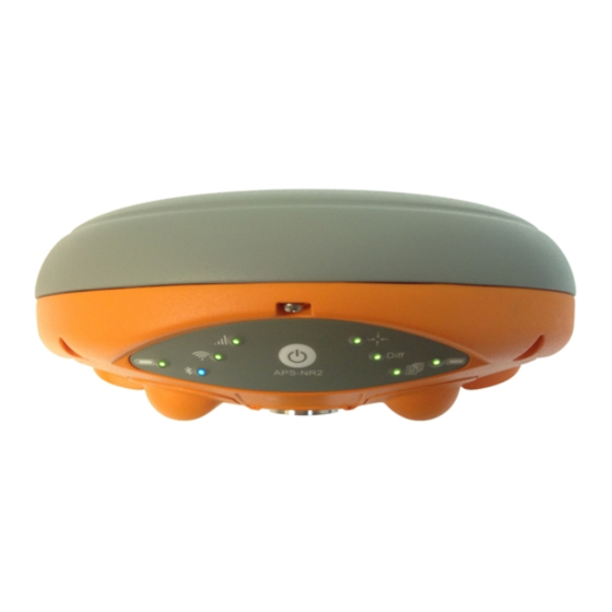
3 Altus NR2 Overview This section will guide you through the main parts of the Altus NR2. Detailed steps on how to con gure the Altus NR2 will be elaborated upon in later sections. 3.1 Front Panel The Altus NR2 has an intuitive front panel with status LEDs and a central power button. -
Page 16: Power Button Functions
3.1. FRONT PANEL 3.1.1 Power Button Functions As well as turning the Altus NR2 off and on, the front-panel power button can also be used to toggle Wi-Fi and internal logging as described in Table 3.1-2. Table 3.1-2: Altus NR2 power button funtions... -
Page 17: Location Of Batteries And Sim Card
3.2. LOCATION OF BATTERIES AND SIM CARD 3.2 Location of Batteries and SIM card The Altus NR2 contains two battery bays. The positive contact for the batteries is that nearest to the front label. The SIM card slot is located under the left battery bay and has a watertight cover. -
Page 18: Altus Nr2 Connector
3.4. ALTUS NR2 CONNECTOR 3.4 Altus NR2 Connector The Altus NR2 has one 9-Pin Lemo connection socket on its underside as shown in Figure 3- 4. When connected to the wall charger, this will power the device and charge any batteries that are inside. -
Page 19: The Web Interface
The Altus NR2 can be fully con gured and monitored using the Web Interface. The following sections will detail how to connect to the Altus NR2 via the Web Interface and use it to make con gurations. Figure 3-5 shows an example of the Overview page of the Web Interface when connected to an Altus NR2 in RTK x mode that is receiving differential corrections via... -
Page 20: Initial Set Up
A Wi-Fi or USB connection to a phone, tablet or computer A Wi-Fi enabled device can be used to con gure the Altus NR2 using the Web Interface. Any device with a USB port can also be used to connect via the Web Interface and con gure the Altus NR2. -
Page 21: Insert The Micro Sim Card
3. Open the SIM card compartment 4. Put the micro SIM card down in the SIM card compartment. 5. Slide the micro SIM card gently towards the front panel of the Altus NR2 until a click sounds. 6. Gently close the SIM card compartment. -
Page 22: Make Sure The Wi-Fi Radio Is Switched On
4.6 Make sure the Wi-Fi radio is switched on The default way of con guring the Altus NR2 is using the Web Interface over Wi-Fi. 1. If the Wi-Fi radio is already switched on, the Wi-Fi LED will be lit (green) 2. -
Page 23: Connect To The Web Interface
Any device with Wi-Fi can connect to the Altus NR2 and use the Web Interface. The Altus NR2 identi es itself as wireless network or an access point by default. Before starting the procedure below, it is advised to get acquainted with the procedure of your device (phone, tablet, computer) for connecting to a Wi-Fi network. -
Page 24: Con Guration Of The Altus Nr2 For Rtk
5 Con guration of the Altus NR2 for RTK 5.1 Basic con guration After successfully executing the steps in ‘Initial set up’, your Altus NR2 is ready to be con gured to receive corrections and output position data. After each change made to the Altus NR2’s con guration while executing the steps in the following sections the pop up will appear in the bottom right of the browser window. -
Page 25: Set Up The Cellular Modem
5.2. SET UP THE CELLULAR MODEM 5.2 Set up the cellular modem 1. Click the Communications/Cellular tab on the Web Interface to show the status of the Cell Modem. 2. Enter a Cellular PIN, APN, Username and Password from this tab. 3. - Page 26 5.2. SET UP THE CELLULAR MODEM Figure 5-4: Cellular Status: Connected...
-
Page 27: Configure As Ntrip Client
5.3 Con gure as NTRIP client 1. Make sure you have a cellular connection as described in the previous section. 2. Select the Corrections/NTRIP tab on the Altus NR2’s Web Interface. Figure 5-5: NTRIP tab of the Web Interface 3. Select ’Client’ in the Mode drop down box. - Page 28 5.3. CONFIGURE AS NTRIP CLIENT Figure 5-7: Receiving differential corrections via NTRIP If the Mode Field is set to ‘Client’, the Altus NR2 will auto-connect to the NTRIP Caster each time it is powered. If the Mode Field is set to ‘Off’, no corrections will be received and the Altus NR2 will...
-
Page 29: Altus Nr2 Configured For
5.4. ALTUS NR2 CONFIGURED FOR RTK 5.4 Altus NR2 Con gured for RTK After nishing the steps in the Sections 5.1 to 5.3, the Altus NR2 is receiving corrections and is able to calculate an RTK position. Figure 5-8: Overview tab after RTK Con guration... -
Page 30: Con Guring The Output
5. Using your preferred GIS or Survey application on the device make sure you connect to the Bluetooth port created by the Bluetooth manager of your device. Unless there are speci c reasons to make the Altus NR2 undiscoverable, it is advised to leave the Discoverable option switched on. -
Page 31: Configure The Nmea For Bluetooth Output
6.2 Con gure the NMEA for Bluetooth output The NMEA tab allows the user to view paired Bluetooth devices and start/stop NMEA. 1. Click the NMEA tab on the Altus NR2’s Web Interface 2. Select the required NMEA messages and the required Interval 3. -
Page 32: A Ctivate L Ogging
6.3 Activate Logging 6.3.1 Basic logging con guration The Logging functionality allows data to be stored on the Altus NR2’s internal 8GB disk. The user may select SBF blocks (Septentrio Binary Format) and/or NMEA messages (National Marine Electronics Association) to be logged. -
Page 33: Advanced Settings For Logging
Typically the Advanced Settings for Logging are not recon gured by the user. This section may therefore be skipped during the initial con guration. The Advanced settings for logging are elaborated in Altus NR2 Firmware Command Line Interface Reference Guide. -
Page 34: Set The Antenna Height
The antenna height is the offset between the measured point and the Antenna Reference Point. Practically this is the height of the survey rod. The Altus NR2 automatically compensates for the Antenna Phase Centre using the approved calibration of the product in order to provide the most accurate position out of the box. -
Page 35: Finalizing The Con Guration
8 Finalizing the con guration 8.1 Make the settings persistent If the user has consistently pressed Save when the pop up shown below has appeared on the screen, all settings will be persistent and will be applied again when the device powered Figure 8-1: Save to Boot pop up If the user is not sure all settings have been stored, the procedure below is to be executed. -
Page 36: Switch Off Wi
8.2. SWITCH OFF WI-FI 4. Click the OK button shown in Figure 8-4 Figure 8-4: OK to execute the copy 8.2 Switch off Wi-Fi The nominal battery lifetime of a full working day can be improved if Wi-Fi is switched off during operation (and only on during con guration). -
Page 37: Retrieving The Collected Data From The Receiver
9 Retrieving the collected data from the receiver As described in Section 6.3, the collected data can be stored on the internal disk. The data can be retrieved over Wi-Fi using the Web Interface or via the USB data cable. 9.1 Using the Web Interface 1. -
Page 38: Using The Usb Connection
9.2.1 Connecting the USB data cable for the time The USB drivers for the Altus NR2 can be installed by following the steps below: Make sure the computer is connected to the internet. Connect the Altus NR2 to a USB port of your computer using the USB cable. -
Page 39: Retrieving Data Via The Usb Connection
2. Connect the Altus NR2 to a USB port of your computer using the USB communication cable. 3. On a Windows computer the Altus NR2 will appear as an extra drive in the le explorer after a few seconds. 4. The Altus NR2 appears as a drive named ‘ A ltus NR2’. -
Page 40: Connecting Via 'Ethernet Over Usb
9.2. USING THE USB CONNECTION 9.2.3 Connecting via ‘Ethernet over USB’ The web Interface of the Altus NR2 can be accessed over an ‘Ethernet over USB’ connection. If the Altus NR2 has not been connected to the computer being used before then rst execute the steps described in the Section 9.2.1. -
Page 41: Con Guration Of The Altus Nr2 As A Base Nr2
10 Con guration of the Altus NR2 as a Base Before you start ... The Altus NR2 offers the possibility of being setup as a Base station receiver. This makes a great companion to any Altus NR2 Rover unit thanks to its point-to-point connectivity features. -
Page 42: Setting The Altus Nr2 Base Station Position
Figure 10-1: Setting the Altus NR2 base station position to static Set the correct position The next step is to set the antenna position of the Altus NR2. The default setting of ‘auto’ can be used for demonstration or for relative positioning however, for most other purposes, a properly surveyed position is advisable. -
Page 43: Altus Nr2 Rtk Rover-To-Base Con Guration (Point To Point)
Base receiver in order to receive corrections. Figure 11-1: Overview of the Base-Rover con guration for differential correction transfer over a cellular connection Step 1: Setting the Altus NR2 base station position Set the Altus NR2 base station position as described in Section 10.1... - Page 44 It is important to remember that with most mobile network providers the assigned IP address of the cellular in the Altus NR2 will be changed every time that a new connection is made. As such the Rover units will need to be aware of the new IP address (some mobile network providers allow you to use Fixed IP addresses with an extra cost).
- Page 45 11.1. ALTUS NR2 RTK BASE-ROVER CELLULAR CONNECTION Figure 11-4: Output RTCMv3 diff corr on the con gured TCP/IP server port of the base station receiver...
- Page 46 Step 3: Con gure Rover input of differential corrections Con gure your cellular connection • Make sure that the Cell modem of the Altus NR2 is connected. Section 5.2. Con gure the IPR connection Setup an IPR (Receive) connection so the unit can accept the diff corr via the Cellular internet connection.
- Page 47 11.1. ALTUS NR2 RTK BASE-ROVER CELLULAR CONNECTION Figure 11-6: Confgure the rover receiver to listen for the diff corr ouptut from the Base station Monitor the incoming stream In the Rover unit the widget in the ‘Corrections/Corrections input’ menu should show the IPR connection accepting corrections.
-
Page 48: Altu Nr2 Rtk Base-Rover Wi-Fi Connection
Base station is con gured as a Wi-Fi access point while the rover is con gured as a client Figure 11-7: Base-Rover con guration using Wi-Fi Step 1: Setting the Altus NR2 base station position Set the Altus NR2 base station position as described in Section 10.1 Step 2: Con gure the base station output of differential corrections... - Page 49 11.2. ALTUS NR2 RTK BASE-ROVER WI-FI CONNECTION NR2 to your PC using the USB cable connected to the ‘Port 1’ socket indicated in Figure 3-4. You can now open an internet browser and connect to web interface using the IP address 192.168.3.1 as shown in Figure 11-8...
- Page 50 11.2. ALTUS NR2 RTK BASE-ROVER WI-FI CONNECTION Con gure the correction stream On the ‘Corrections Output’ tab, you can select the format and individual differential correction messages that you want to send to the rover receiver. Make sure to select the same IPS connection you con gured in the previous step.
- Page 51 For this reason, the rover should be con gured using the USB connection. The steps below describe how to connect via USB to the Altus NR2 and con gure it in Wi-Fi client mode.
- Page 52 11.2. ALTUS NR2 RTK BASE-ROVER WI-FI CONNECTION Figure 11-14: Select the base station device from the list of reachable networks • Close the screen and click the ‘OK’ button to apply the settings. Con gure the input of differential corrections On the ‘Corrections Input’...
- Page 53 11.2. ALTUS NR2 RTK BASE-ROVER WI-FI CONNECTION Con gure the IPR connection Setup an IPR (Receive) connection for reception of differential corrections. On the ‘Communication/IP Settings’ menu, con gure and IPR connection with the same port number con gured for the Base station and the IP address 192.168.20.1 as shown in Figure 11-16.
-
Page 54: Pinpoint-Gis
PinPoint-GIS App. PinPoint-GIS Web PinPoint-GIS Web is an extension of Septentrio’s web interface with a direct link to ArcGIS Online. It offers a unique solution with the power to run GIS collection inside Septentrio GNSS receivers. No extra applications are needed, simply use your preferred web browser for full GIS work ow - from accurate data collection in the eld directly to the ArcGIS Online Cloud. - Page 55 12.1. INTRODUCTION The PinPoint-GIS App can work alongside any other Android app to provide an interface between the receiver and the mobile device. To give an idea of the difference between the Web and App versions of PinPoint-GIS, Table 12.1-1 summarises their various functionalities when working in conjunction with Esri’s well-know ArcGIS Online tools.
-
Page 56: Creating A Map 12.3 C
12.2. CREATING A MAP 12.2 Creating a map To be able to use PinPoint-GIS Web or App you will need an ArcGIS Online account. ArcGIS accounts are either public (free) or commercial (payable). Public accounts allow you to create your own maps using feature layers which are publicly available on the internet.They are useful for demonstrating PinPoint-GIS functionality and for simple collections. - Page 57 12.2. CREATING A MAP 3-Prepare your map You can add different layers to your map Layers can be either collectable or non-collectable (e.g. a tra c layer is not collectable while a manhole inspection layer will have some collection possibilities) Add Layers by clicking on ‘...
-
Page 58: C Onnecting To The Internet
Altus NR2 (using the URL: http://192.168.20.1). Make sure the GSM of the Altus NR2 is on and connected to the internet. You can con gure the cellular modem on the Communication/ cellular tab on the web interface. -
Page 59: Using Pinp
GIS and accurate data collection. The following steps will guide you through the main functionalities of PinPoint-GIS Web in combination with the Altus NR2 receiver. The PinPoint-GIS view is located in the GNSS/PinPoint-GIS menu of the web interface as shown in Figure 12-2. Within this view you have full access to your ArcGIS Online user maps. - Page 60 12.4. USING PINPOINT-GIS WEB Figure 12-3: Functions within PinPoint-GIS Web Access your maps from the Altus NR2 Connect to your Altus NR2 receiver Go to the GNSS/PinPoint-GIS Web tab where you should see a basic map Your browser should be connected to the internet (See Section 12.3).
-
Page 61: Optional: Auto Lling Of Gnss Attributes 1
SBF blocks can be found at the Reference guide of the Altus NR2. It is also possible within the web interface to check the Message inspector located in the Expert Console menu so that you can visualize the elds which could be lled. - Page 62 12.4. USING PINPOINT-GIS WEB Table 12.4-4: Type conversion for auto lled GNSS attributes To be able to add extra attributes to a GIS database will need to use either ArcGIS Online or ArcGIS PRO Desktop SW. The step below explain how to prepare a map for auto lling of GNSS data using ArcGIS Online.
- Page 63 5. Once you have added the eld, please make sure you save your map. 6. Once saved, when you add a collection in ArcGIS Online you will see the form eld automatically lled by the Altus NR2 Figure 12-6: Auto- lled values in PinPoint-GIS Web...
-
Page 64: Using The Pin
• Basic GNSS control: WiFi, GSM With the PinPoint-GIS App, you can choose to use either the internal cellular connection of the Altus NR2, or the connection of your mobile device. The diagrams above show schematically the connection options. The PinPoint-GIS App is an application which can be used along with any other Android applications. - Page 65 The application is freely available in the Android Play store and can be used with the Altus NR2, Altus GeoPod or the APS-3 receiver. The following steps will guide you through using PinPoint-GIS App with the Altus NR2 receiver using Collector for ArcGIS as an example.
- Page 66 The current location will be shown (if location overriding is enabled then the GPS accuracy will be the one from the Altus NR2) Select the ‘+’ sign to add a collection element A map prepared for collection will have a feature layer attached to the map and ready for collection (enough permissions).
-
Page 67: Hot Swapping The Batteries And Charging
Both the Web Interface and front panel LEDs give information about the battery status. Table 13.1-1: Battery not in use Table 13.1-2: Battery in use When both batteries are below 5% then the Altus NR2 will make use of both batteries. The user may replace either battery without interrupting operation. -
Page 68: B Attery C Harging
3400 mAh a charging time of 3 to 4 hours can be expected. 13.2.2 Using the A/C adapter The batteries of the Altus NR2 can be charged in the device while it it connected to an external power supply. If the Altus NR2 is switched off during charging then there is no visual indication of the charging: all front-panel LEDs remain off. -
Page 69: System Administration Using The Web Interface
14.1 Con guration 14.1.1 What is a con guration? A collection of all settings and values that determine the behavior of the Altus NR2 are called a con guration. The con guration that is actually being used is the Current con guration. -
Page 70: C Onfiguration
14.1. CONFIGURATION the Altus NR2 allows storing two user pro les or user con gurations, User 1 and User2. The user can store a con guration into a user pro le by simply copying the Boot or the Current con guration to User1 or User2. -
Page 71: Managing Con Gurations
Intermediate saving of the Con guration After each change made to the Altus NR2’s con guration while executing the steps in the following sections a pop up will appear in the bottom right of the browser window. - Page 72 14.1. CONFIGURATION Figure 14-2: Save to Boot pop-up...
-
Page 73: Reset
The RxDefault con guration is copied into the receiver’s Boot and Current Con g con gurations. The User1 and User2 con gurations remain unchanged. Bluetooth All information about previously paired devices is cleared. Table 14.1-4: Altus NR2 Reset- Memory Erase Options... -
Page 74: Firmware Upgrade
5. Click the Browse button and navigate to the folder where you stored the .suf les. Select the ( rst) .suf le to be loaded into the Altus NR2. After selecting the .suf le its name will appear next to the Browse button. -
Page 75: Expert Console
The drop down box showing ‘Mainboard (APS NR2)’ in Figure 14-5 allows selecting the Altus NR2’s sub system the commands will be directed to. The sub systems of the Altus NR2 are the Mainboard (APS NR2), GNSS Receiver and the Cell modem. Responses will be shown the window below the label Expert Console. -
Page 76: About
14.1. CONFIGURATION 14.1.6 About The Altus NR2’s speci c hardware and software components can be inspected in the About menu. The Receiver Identi cation will show this information. Also, the user may select to obtain a Diagnostic Report. Figure 14-6: Web Interface Admin-About... -
Page 77: Status Icons On The 15.2 Front Panel Led S
15 Appendix 15.1 Status Icons on the Web Interface The icons on the right hand side of the top banner quickly show the user the status of the Altus NR2. Table 15.1-1: Web Interface Status Icons... - Page 78 15.2. FRONT PANEL LEDS 15.2 Front Panel LEDs Figure 15-1: Front-panel LED behaviour...
-
Page 79: The Batteries
• Flexible chargers that can charge batteries of different technologies (e.g. Li-Ion and NiMH) typically will not optimally charge the batteries. The Altus NR2’s batteries can also be charged while they are in the device using the supplied wall charger. -
Page 80: And Pin Point -Gis Terms
15.5. GLOSSARY OF ARCGIS AND PINPOINT-GIS TERMS 15.5 Glossary of ArcGIS and PinPoint-GIS terms A geographic information system (GIS) describes any information system that can integrate, store, edit, analyse, share, and display geographic information. applications allow users to analyse spatial information, edit data in maps and present the results of these operations ArcGIS Online Web system which allows custom map creation... -
Page 81: Elated Acronyms
15.6. LIST OF TYPICAL GNSS RELATED ACRONYMS 15.6 List of Typical GNSS Related Acronyms APME A Posteriori Multipath Estimation Antenna Reference Point ASCII American Standard Code for Information Interchange Compact Measurement Record Central Processing Unit Carriage Return Clear to Send DGPS Differential Global Positioning System Dilution of Precision...
Need help?
Do you have a question about the Altus NR2 and is the answer not in the manual?
Questions and answers