Table of Contents
Advertisement
Advertisement
Table of Contents

Related Manuals for SEPTENTRIO AsteRx-U


Summary of Contents for SEPTENTRIO AsteRx-U
- Page 1 AsteRx-U User Manual...
- Page 2 July 27, 2017 Thank you for choosing the AsteRx-U! This user manual provides detailed instructions on how to use AsteRx-U and we recommend that you read it carefully before you start using the device. Please note that this manual provides descriptions of all functionalities of the AsteRx-U product family however, the particular AsteRx-U you purchased may not support functions speci c to certain variants.
-
Page 3: Table Of Contents
RTK ......... . . 32 OW TO CONFIGURE THE 4.1.1 How to con gure the AsteRx-U in RTK rover mode using the UHF radio . . 32 4.1.2 How to con gure the AsteRx-U in RTK rover mode using the cellular modem and NTRIP . - Page 4 CONTENTS -U......42 SING BAND CORRECTION DATA WITH THE OW TO CONFIGURE THE ................. . . 48 TTITUDE .
-
Page 5: Introduction
1 Introduction 1.1 User Notices 1.1.1 CE Notice AsteRx-U receivers carry the CE mark and are as such compliant with the 2004/108/EC - EMC Directive and amendments, 2006/95/EC - Low Voltage Directive, both amended by the CE-marking directive 93/68/EC. With regards to EMC, these devices are declared as class B, suitable for residential or business environment. -
Page 6: Support
1.1. USER NOTICES 1.1.4 Support For rst-line support please contact your AsteRx-U dealer. Further information can be found on our website or by contacting Septentrio Technical Support. http://www.septentrio.com support@septentrio.com Europe Septentrio NV Phone: +32 16 300 800 Greenhill Campus Fax: +32 16 221 640 Interleuvenlaan 15i, sales@septentrio.com... -
Page 7: Asterx-U Overview
GNSS Heading, L-Band positioning and wireless communications within a rugged IP67 housing for the broadest range of applications. Use any smartphone, tablet or computer to operate the AsteRx-U without any special con guration software via the built-in webserver accessible via WiFi, Ethernet or USB connection. - Page 8 • Integrated Bluetooth (2.1 + EDR/4.0) • Integrated Quadband Cellular Modem (EDGE, 2G, 3G, 3.5G) • Integrated WiFi (802.11 b/g/n) • Integrated UHF (406-470 MHz) (AsteRx-U UHF and MARINE variants only) • Connector for separate L-Band antenna (AsteRx-U MARINE variant only)
-
Page 9: Physical And Environmental
MIL-STD-810G, Method 510.5, Procedure I Shock MIL-STD-810G, Method 516.6, Procedure I/II Vibration MIL-STD-810G, Method 514.6, Procedure I 2.2 AsteRx-U variants The AsteRx-U is available in three variants: Variant Main features (Part number) • Integrated cellular modem AsteRx-U • Integrated WiFi modem (410121) •... -
Page 10: Asterx-U Design
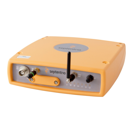
2.3. ASTERX-U DESIGN 2.3 AsteRx-U design 2.3.1 Front panel The front-panel layout of the AsteRx-U with attached Bluetooth/WiFi and Cellular antennas is shown in Figure 2-1. Figure 2-1: AsteRx-U front-panel layout... -
Page 11: Led Description
2.3. ASTERX-U DESIGN 2.3.2 LED description Icon Behaviour Off: Bluetooth disabled On: Bluetooth connected blue Blinking slowly: Not connected but discoverable Off: WiFi disabled On: Access-point mode or client mode Blinking slowly: Establishing a connection in client mode green Blinking quickly: Error, not connected Off: Not logging... -
Page 12: Rear Panel
Figure 2-2: AsteRx-U rear-panel layout 2.3.4 SIM card slot The SIM card can be inserted into the slot in the front panel of the AsteRx-U as shown in Figure 2-3. Important: Only insert or remove the SIM card while the unit is powered down. -
Page 13: Mounting Brackets
Figure 2-4: Mounting brackets tted to AsteRx-U 2.3.6 Internal memory The AsteRx-U has an 8 GB Memory for internal data logging. Data can be logged in SBF or NMEA format and may be retrieved via the logging tab of the web interface. -
Page 14: Shipping Case Contents
2.4. SHIPPING CASE CONTENTS 2.4 Shipping case contents 2.4.1 Supplied as standard The following items with their part numbers are supplied as standard with the AsteRx-U. -
Page 15: Optional Items
2.4. SHIPPING CASE CONTENTS 2.4.2 Optional items The following items with their part numbers can be optionally purchased for use with the AsteRx-U. -
Page 16: Quick Start
There is a power button on the front panel as shown in Figure 3-2 which you may also have to press. If the AsteRx-U loses power while the power button is on, then it will automatically boot up when power is restored. -
Page 17: Connecting An Antenna
3.2. CONNECTING AN ANTENNA 3.2 Connecting an antenna The rear panel of the AsteRx-U has two TNC connectors for GNSS antennas: one for the main antenna and one for an auxiliary antenna for heading applications. The AsteRx-U MARINE has an additional TNC connector for a dedicated L-Band antenna. To get started, connect an antenna via an antenna cable to the main antenna connector of the AsteRx-U indicated in Figure 3-3. - Page 18 The USB connection on the AsteRx-U functions as network adapter and the DHCP server running on the receiver will always assign the AsteRx-U the IP address 192.168.3.1. To connect to the AsteRx-U, you can then simply open a web browser using the IP address 192.168.3.1 as shown in Figure 3-6.
-
Page 19: Using The Ethernet Cable
By default, the AsteRx-U has a DHCP address ‘http://Asterx-U-xxxxxxx’, where xxxxxxx are the 7 digits of the AsteRx-U serial number. The serial number can be found on a sticker on the corner of the outer casing of the receiver. Figure 3-8 shows a screenshot of an Ethernet connection to a receiver with serial number 3011881 using ‘http://asterx-u-3011881’. -
Page 20: Over Wifi
WiFi signals: the AsteRx-U identi es itself as a wireless access point named ’ A steRx-U-serial number’. The serial number of the AsteRx-U can be found on an identi cation sticker on the receiver housing. Select and connect to the AsteRx-U as shown in Figure 3-9. -
Page 21: How To Configure Sbf And Nmea Output
Step 1: Con gure the serial COM port The COM port of the AsteRx-U should be con gured with the same baud rate and ow control setting of the coupled device. These settings can be con gured via the ‘Communication’ tab as shown in Figure 3-11. - Page 22 3.4. HOW TO CONFIGURE SBF AND NMEA OUTPUT Step 2: Con gure data output NMEA In the ‘NMEA/SBF Out’ tab, clicking on ‘New NMEA Stream’ will guide you through the steps needed to con gure NMEA output as shown in Figures 3-12 and 3-13. Figure 3-12: Selecting to output NMEA data on COM3 Figure 3-13: Selecting to output the GGA NMEA message every second...
- Page 23 3.4. HOW TO CONFIGURE SBF AND NMEA OUTPUT By clicking ‘New SBF stream’, a second output stream can be con gured. In the example shown in Figures 3-14 and 3-15 the PVTCartesian SBF data block will be output over COM1 once per second.
- Page 24 3.4. HOW TO CONFIGURE SBF AND NMEA OUTPUT Step 3: Verifying the con guration Having con gured data output and clicked on ‘Ok’ the ‘NMEA/SBF Out’ page will now display a summary of all data output as shown in Figure 3-16. Figure 3-16: Summary of all con gured data output streams Figure 3-17 shows the actual data output.
-
Page 25: Output Over Ethernet
3.4. HOW TO CONFIGURE SBF AND NMEA OUTPUT 3.4.2 Output over Ethernet SBF and NMEA data can be sent over an Ethernet connection to the AsteRx-U. Step 1: Con gure an IP connection on the AsteRx-U The Ethernet port settings can be con gured by selecting ‘IP Ports’ from the Communication menu. - Page 26 3.4. HOW TO CONFIGURE SBF AND NMEA OUTPUT Step 2: Con gure output of NMEA messages In the NMEA/SBF Out window, click on ‘New NMEA stream’ and follow the sequence of windows to con gure the data you want to output. In the example shown in Figure 3-19, the NMEA GGA message will be output every second.
- Page 27 3.4. HOW TO CONFIGURE SBF AND NMEA OUTPUT Step 3: Con gure Data Link to listen for NMEA output The screenshots in Figure 3-20 show how the Septentrio GUI tool Data Link can be con gured to listen for the AsteRx-U GGA output.
-
Page 28: Output Over Bluetooth
Both SBF and NMEA data formats can be sent over bluetooth. This example shows how to forward NMEA data to an App called MachineryGuide on a Getac Android device. Step 1: Con gure the Bluetooth connection on the AsteRx-U On the Overview tab of the Web Interface, you can make sure that Bluetooth has been enabled. - Page 29 3.4. HOW TO CONFIGURE SBF AND NMEA OUTPUT Step 2: Con gure NMEA messages to output In the NMEA/SBF Out window, click on New NMEA Stream as in Figure 3-24. This will guide you through the various steps to con gure NMEA output. Select Bluetooth as the connection type as shown.
- Page 30 Figures 3-25 and 3-26 show how the MachineryGuide App can be con gured to use NMEA data from the AsteRs-U over bluetooth. Figure 3-25: Select bluetooth for GPS positioning information Figure 3-26: Find and pair the device to the AsteRx-U...
- Page 31 3.4. HOW TO CONFIGURE SBF AND NMEA OUTPUT Step 4: Verifying the con guration When the AsteRx-U has been paired with a device and is sending data, the NMEA/SBF Out page will show a graphic similar to that shown in Figure 3-27.
-
Page 32: Rover Operation
4 Rover operation 4.1 How to con gure the AsteRx-U for RTK The AsteRx-U can use correction data to calculate a cm-level RTK position. The AsteRx-U can get this correction data in several ways: using the build-in UHF radio, over GSM/GPRS or Ethernet. -
Page 33: How To Configure The Asterx-U For Rtk
Clicking on ‘Save’ will cause the AsteRx-U to boot with the new con guration after a power cycle. - Page 34 4.1. HOW TO CONFIGURE THE ASTERX-U FOR RTK Step 3: Verifying the con guration If the UHF radio of the AsteRx-U has been correctly con gured then you should see in the UHF/DiffCorr eld, the greyed-out connection line now replaced by a ‘live’ green line as in Figure 4-3.
-
Page 35: How To Con Gure The Asterx-U In Rtk Rover Mode Using The Cellular
4.1. HOW TO CONFIGURE THE ASTERX-U FOR RTK 4.1.2 How to con gure the AsteRx-U in RTK rover mode using the cellular modem and NTRIP Step 1: Enable RTK mode Ensure that RTK is be enabled as a positioning mode. This can be done in the GNSS, Position tab by checking the ‘RTK’... - Page 36 4.1. HOW TO CONFIGURE THE ASTERX-U FOR RTK Step 2: Con gure the cellular modem Insert a SIM card into the front-panel slot of the AsteRx-U as shown in Figure 2-3 while the unit is powered down. The on-board cellular modem of the AsteRx-U can be con gured in the Communication, Cellular window as shown in Figure 4-5.
- Page 37 Using a cellular connection you can get RTK correction data from an NTRIP service. Figure 4-7 shows the settings required to retrieve correction data from the Septentrio NTRIP Caster. Select ‘Client’ from the drop-down Mode menu. The Caster, Port, User Name and Password should be provided by the NTRIP service.
- Page 38 4.1. HOW TO CONFIGURE THE ASTERX-U FOR RTK Step 4: Verifying the con guration When both the cellular modem and NTRIP connection have been correctly con gured, the Ntrip gure in Corrections NTRIP window will indicate differential correction reception as shown in Figure 4-9 with the positioning mode icon indicating RTK xed.
-
Page 39: How To Con Gure The Asterx-U In Rtk Rover Mode Using Tcp/Ip In A
Step 1: Con gure the Base station receiver Set the Base station position as static Section 5.1 describes how to con gure the AsteRx-U as an RTK base station. Con gure the Ethernet connection and diff corr output from the Base... - Page 40 4.1. HOW TO CONFIGURE THE ASTERX-U FOR RTK Step 2: Con gure the Rover receiver Enable RTK positioning mode on the rover receiver Ensure that RTK is enabled as a positioning mode. This can be done in the GNSS Position tab by checking the ‘RTK’...
- Page 41 4.1. HOW TO CONFIGURE THE ASTERX-U FOR RTK Step 3: Verifying the con guration If the Base station and rover receivers have been con gured correctly then graphics in the Communication Ethernet windows should appear similar to those shown in Figures 4-13 and 4-14.
-
Page 42: Using L- Band Ppp Correction Data With The Aste Rx
Step 1: Check you have PPP permissions on your AsteRx-U The use of PPP services is permission- le controlled on the AsteRx-U. You can make sure that you have PPP permissions enabled on the About page selected from the Admin menu. Click on Permitted Capabilities and scroll down the list of permissions: PPP and Augmented Data Svc should appear as permitted as shown in Figure 4-15. - Page 43 You can nd out more about VERIPOS services via the link: www.veripos.com/services.html. To activate the VERIPOS service, you will be asked to provide the Augmentation User ID of the AsteRx-U which can be found in the Admin, About window and is shown highlighted in Figure 4-17.
- Page 44 Step 3: Connect an L-Band antenna Ensure that you have an L-band capable antenna connected to the main antenna rear-panel connector. The AsteRx-U MARINE variant offers an additional connector for a dedicated L-band antenna as shown in Figure 4-18. Figure 4-18: Rear panel antenna connectors...
- Page 45 PPP correction type as shown. Figure 4-20: Select L-Band beam and APEX/ULTRA correction type (only applicable for VERIPOS service) Without a TerraStar or VERIPOS subscription, the AsteRx-U will still be able track visible L-Band signals. Figure 4-21 shows the L-Band Tracker Status eld when the AsteRx-U is locked onto signals from the AORE satellite which transmits at 1539.9825 Mz.
- Page 46 4.2. USING L-BAND PPP CORRECTION DATA WITH THE ASTERX-U Step 6: Verifying the con guration With a valid TERRRASTAR or VERIPOS subscription, the AsteRx-U will be able to decode PPP correction data. The Access line in the L-band decoder Information eld should show Access Enabled as in Figure 4-22.
- Page 47 4.2. USING L-BAND PPP CORRECTION DATA WITH THE ASTERX-U Step 6: Additional optional settings: RTK seeding The AsteRx-U can use an RTK or DGPS position to reduce the PPP convergence time: a process known as seeding. The con guration elds for seeding can be found in the GNSS, Position window as shown in Figure 4-23.
-
Page 48: How To Configure The Asterx-U For
Attitude With two antennas connected to the AsteRx-U, the receiver can calculate Heading and either Pitch or Roll. This section details how to con gure the AsteRx-U in a two-antenna setup. Step 1: Connect a second antenna Connect a second antenna to the rear-panel connector labelled AUX ANT and indicated in Figure 4-24. - Page 49 4.3. HOW TO CONFIGURE THE ASTERX-U FOR ATTITUDE Step 2: Con gure attitude settings The attitude settings of the AsteRx-U can be con gured in the GNSS, Attitude window as shown in Figure 4-25. Figure 4-25: GNSS Attitude window when two antennas are connected...
- Page 50 SBF output via the NMEA/SBF Out window as Figure 4-26 shows. Figure 4-26: SBF blocks containing attitude information NMEA You can output the attitude information from the AsteRx-U in NMEA format by selecting the standard NMEA HDT sentence or the Septentrio proprietary HRP sentence as shown in Figure 4-27.
-
Page 51: How To Output Apps Signal
4.4. HOW TO OUTPUT A PPS SIGNAL 4.4 How to output a PPS signal The AsteRx-U can output a PPS (Pulse-per-Second) signal that can be used for example, to synchronise a secondary device to UTC time. Step 1: Connect the PPS cable Connect the PPS_OUT cable to the rear-panel connector labelled ‘PPS GPO’... -
Page 52: Time Synchronisation Using The Pps Signal
The PPS signal is an electronic pulse synchronised with GPS time clock ticks, it doesn’t itself specify time. To synchronise a device with GPS time, the AsteRx-U can be con gured to output both a PPS signal and an NMEA ZDA sentence which contains the time. The PPS signal arrives rst followed by the ZDA whose reported time corresponds to the leading edge of the PPS signal. -
Page 53: Base Station Operation
Set the position as static To work as a base station, the position of the AsteRx-U should be set to static. If not, the AsteRx-U will still work as a base station however the position of the rover may show more variation. - Page 54 5.1. HOW TO CONFIGURE THE ASTERX-U AS AN RTK BASE STATION USING THE UHF RADIO Select the Datum of the antenna position In the Datum eld, you can select the datum to which the antenna coordinates refer. The selected value is stored in the Datum eld of position-related SBF blocks (e.g.
- Page 55 5.1. HOW TO CONFIGURE THE ASTERX-U AS AN RTK BASE STATION USING THE UHF RADIO Step 3: Con guring the UHF radio The UHF radio can be con gured in the ‘UHF’ window. In the example show in Figure 5-4, the radio will transmit at a frequency of 410 MHz, channel spacing of 12.5 kHz and at a power of...
- Page 56 5.1. HOW TO CONFIGURE THE ASTERX-U AS AN RTK BASE STATION USING THE UHF RADIO Step 4: Verifying the con guration If the UHF radio has been correctly con gured, the transmission line in the top-panel should change to green as shown in Figure 5-5. The format of the corrections stream should also be correctly identi ed along with the data rate.
-
Page 57: Configuring The Asterx-U Ntrip Caster
10 NTRIP clients (or rovers) over the internet. The caster supports up to three mount points and can also broadcast correction data from a remote NTRIP server. All settings relating to the AsteRx-U NTRIP Caster can be con gured on the NTRIP Caster window from the Communication menu. - Page 58 Client authentication for the mount point: none - any client can connect without logging in or, basic - clients have to login with a username and password. To select a correction stream from the NTRIP server of the AsteRx-U, select ‘No’ in the ‘ A llow external server’ eld Click on the ‘Local Server ...’...
- Page 59 5.2. CONFIGURING THE ASTERX-U NTRIP CASTER Figure 5-8: Connecting as a client to the AsteRx-U NTRIP Caster On the NTRIP Client side Rover receivers can connect to the NTRIP Caster by entering its IP address and Port as shown in Figure 5-9. After clicking ‘Ok’, the mount point source table will be lled and a mount point can be selected.
-
Page 60: Receiver Monitoring
6.1 Basic operational monitoring The ‘Overview’ page of the web interface in Figure 6-1 shows at a glance a summary of the AsteRx-U’s operational status. Figure 6-1: Overview page of the web interface The main information bar at the top of the window gives some basic receiver information: receiver type, serial number and position. - Page 61 6.1. BASIC OPERATIONAL MONITORING The icons to the right of the information bar show that, in this example, the position of the receiver is xed, the overall perfomance (signal quality and CPU) is Excellent (5 out of 5 bars) and the receiver is logging to the internal disk. The Corrections icon indicates that differential corrections are being sent out to a rover receiver.
-
Page 62: Aim+: Using The Spectrum Analyser To Detect And Mitigate Interference
6.2 AIM+: Using the spectrum analyser to detect and mitigate interference The AsteRx-U is equipped with a sophisticated RF interference monitoring and mitigation system (AIM+). To mitigate the effects of narrow-band interference, 3 notch lters can be con gured either in auto or manual mode. These notch lters effectively remove a narrow part of the RF spectrum around the interfering signal. -
Page 63: Narrowband Interference Mitigation
6.2. AIM+: USING THE SPECTRUM ANALYSER TO DETECT AND MITIGATE INTERFERENCE 6.2.1 Narrowband interference mitigation Con guring the notch lters In the default auto mode of the notch lters, the receiver performs automatic interference mitigation of the region of the spectrum affected by interference. In manual mode as shown con gured for Notch1 in Figure 6-3, the region of the affected spectrum is speci ed by a centre frequency and a bandwidth which is effectively blanked by the notch lter. -
Page 64: Wideband Interference Mitigation
There are also intentional sources of interference from devices such as chirp jammers. The wideband interference mitigation system (WBI) of the AsteRx-U can reduce the effect of both types of interference on GNSS signals. Con guring WBI mitigation The wideband interference mitigation system (WBI) can be enabled by selecting ‘on’... - Page 65 6.2. AIM+: USING THE SPECTRUM ANALYSER TO DETECT AND MITIGATE INTERFERENCE When WBI mitigation is enabled, the effect of the interference is dramatically reduced to the extent that, the small signal bump at the GPS L1 central frequency of 1575 MHz is clearly visible as Figure 6-7 shows.
-
Page 66: How To Log Data For Problem Diagnosis
6.3. HOW TO LOG DATA FOR PROBLEM DIAGNOSIS 6.3 How to log data for problem diagnosis If the AsteRx-U does not behave as expected and you need to contact Septentrio Support Department, it is often useful to send a short SBF data le that captures the anomalous behaviour. - Page 67 Figure 6-9: The Logging window showing an active logging session Step 2: Downloading the logged SBF le To download a data le logged on the AsteRx-U, click the download icon next to the lename on the Disk Contents tab as shown in Figure 6-10...
-
Page 68: Activity Logging
6.4. ACTIVITY LOGGING 6.4 Activity logging The AsteRx-U reports various events in the Receiver Messages window of the Admin menu that can be used to check receiver operations. The example in Figure 6-11 shows that four, 15 minute SBF les have been successfully FTP pushed to a remote location. -
Page 69: Receiver Administration Operations
The IP settings of the AsteRx-U can be con gured on the Ethernet window of the Web Interface. By default, the AsteRx-U is con gured to use DHCP to obtain an IP address but, a static IP address can also be con gured as shown in Figure 7-1. -
Page 70: How To Configure Dynamic Dns
IP address is currently assigned to it. To make use of this feature on the AsteRx-U, you should rst create an account with a Dynamic DNS provider (dyndns.org or no-ip.org) to register a hostname for your receiver. -
Page 71: How To Control Access Using The Asterx-U Firewall
7.3 How to control access using the AsteRx-U Firewall You can control access to the AsteRx-U using the receiver’s rewall in the Firewall window. By default, all Ethernet and WiFi ports are open as are the cellular IPS ports (i.e. those de ned on the IP Ports menu). -
Page 72: How To Upgrade The Firmware Or Upload A New Permission File
.suf (Septentrio Upgrade Format) and can be uploaded to the AsteRx-U as shown in the steps below. Firmware upgrades can be downloaded from the Septentrio website and are free for the lifetime of the receiver. Permission les enable additional features on the AsteRx-U and can be purchased via our sales department. - Page 73 Step 2: Verifying the upgrade If there were no problems with the upgrade the message ‘Upgrade successful’ will appear. You can then check on the Admin About tab that the AsteRx-U rmware or permission le has correct, new version as indicated in Figure 7-7.
-
Page 74: How To Set The Asterx-U To Its Default Configuration
Admin Reset tab as shown in Figure 7-9, different functionalities can be individually reset. A ‘Soft’ level reset will cause the AsteRx-U to boot up with its current con guration while a ‘hard’ reset will use the con guration stored in the boot le. -
Page 75: How To Copy The Configuration From One Receiver To Another
7.7 How to copy the con guration from one receiver to another In the Admin Con gurations tab, the con guration of an AsteRx-U can be easily saved to a PC as a text le. A saved con guration can also be uploaded to an AsteRx-U. - Page 76 7.7. HOW TO COPY THE CONFIGURATION FROM ONE RECEIVER TO ANOTHER Select the con guration le to be uploaded then click on OK on the status pop-up as shown in Figure 7-12. Figure 7-12: Select the con guration le to upload...
-
Page 77: Security
8 Security 8.1 Default access to the AsteRx-U You can manage the access that users have to the AsteRx-U in the ‘User Administration’ window of the ‘Admin’ menu. By default, all communications are assigned User-level access as shown in Figure 8-1. ‘User’... -
Page 78: User Access: An Example
After de ning the Users/Viewers and their access levels, they can login on the web interface by clicking on Log in on the upper-right corner as shown in Figure 8-4. Figure 8-4: Logging in to the AsteRx-U web interface... -
Page 79: Using Ssh Key Authentication
By default, anonymous users have full access over FTP, SFTP and rsync to the les logged on the AsteRx-U. FTP, SFTP and rsync access can be limited by con guring user access, as described in Section 8.1. For added security, user authentication for SFTP and rsync access can be con gured using an SSH public key. -
Page 80: Appendix
9 Appendix 9.1 Rear-panel port descriptions 9.1.1 PWR Figure 9-1: 4-pin female socket pin-numbering guide as viewed end on. Start counting at pin indicated by bold semi-circle and follow the line in an anti-clockwise direction. This socket can be paired with a LEMO multipole male connector of type PIN # Name Comment... -
Page 81: Event/Gp1
9.1. REAR-PANEL PORT DESCRIPTIONS 9.1.3 Event/GP1 Figure 9-3: 7-pin female socket pin-numbering guide as viewed end on. Start counting at pin indicated by bold semi-circle and follow the line in an anti-clockwise direction. This socket can be paired with a LEMO multipole male connector of type PIN # Name Comment... -
Page 82: Com1/Com3/Host Usb
9.1. REAR-PANEL PORT DESCRIPTIONS 9.1.5 COM1/COM3/Host USB Figure 9-5: 14-pin female socket pin-numbering guide as viewed end on. Start counting at pin indicated by bold semi-circle and follow the line in an anti-clockwise direction. This socket can be paired with a LEMO multipole male connector of type The USB Host feature will only become fully functional in later rmware versions. -
Page 83: Ethernet/Usb
9.1. REAR-PANEL PORT DESCRIPTIONS 9.1.6 Ethernet/USB Figure 9-6: 16-pin female socket pin-numbering guide as viewed end on. Start counting at pin indicated by bold semi-circle and follow the line in an anti-clockwise direction. This socket can be paired with a LEMO multipole male connector of type PIN # Name Comment... -
Page 84: Uhf Radio Baud Rates
9.2. UHF RADIO BAUD RATES 9.2 UHF radio baud rates The receiver automatically adapts the baud rate according to the UHF channel bandwidth (12.5 or 25 kHz). The parameters associated with the different protocols are given in the table below. When sending correction data for multiple constellations and frequencies at rates of 1 Hz and greater, the lowest baud rate con gurations (9600 and 4800 baud) may not be su cient and you should select a protocol/bandwidth combination for 19200 baud.
Need help?
Do you have a question about the AsteRx-U and is the answer not in the manual?
Questions and answers