Table of Contents
Advertisement
Quick Links
Advertisement
Table of Contents

Related Manuals for SEPTENTRIO AsteRx SBi3


Summary of Contents for SEPTENTRIO AsteRx SBi3
- Page 1 AsteRx SBi3 User Manual...
- Page 2 May 06, 2021 Thank you for choosing the AsteRx SBi3! This user manual provides detailed instructions on how to use AsteRx SBi3 and we recommend that you read it carefully before you start using the device. Please note that this manual provides descriptions of all functionalities of the AsteRx SBi3 product family however, the particular AsteRx SBi3 you purchased may not support functions specific to certain variants.
-
Page 3: Table Of Contents
Top case ................3 Configuring the AsteRx SBi3 3 . -
Page 4: Introduction
1 Introduction 1.1 User Notices 1.1.1 CE Notice AsteRx SBi3 receivers carry the CE mark and are as such compliant with the 2014/53/EU âĂŞ Radio Equipment Directive (RED), 2011/65/EU âĂŞ Restriction of Hazardous Substances (RoHS) Directive and 93/68/EC - CE-marking Directive. -
Page 5: Safety Information
Statement 1: The power supply provided by Septentrio (if any) should not be replaced by another. If the receiver is used with a different power supply than provided by Septentrio, it must have a double isolated construction and must match the specifications of the provided power supply. -
Page 6: Support
Guide and the latest officially supported Firmware version are readily available for download. In case the AsteRx SBi3 does not behave as expected and you need to contact Septentrio’s Technical Support department, you should attach a short SBF log file containing the support blocks and a Diagnostic Report of the receiver. -
Page 7: Asterx Sbi3 Overview
It can also be used as a single antenna receiver for systems with no slip motion. Use of the AsteRx SBi3 as a single antenna INS solution should be limited to use cases where the heading of the vehicle matches the direction of motion. -
Page 8: Powering The Receiver
CHAPTER 2. ASTERX SBI3 OVERVIEW The power consumption of the AsteRx SBi3 depends on its configuration. The following settings directly influence the amount of power consumed: • The number of enabled GNSS frequency bands. For example, a receiver configured to track signals only in the L1 and L2 bands will consume less than a receiver configured to track in the L1, L2 and L5 bands. -
Page 9: Asterx Sbi3 Design
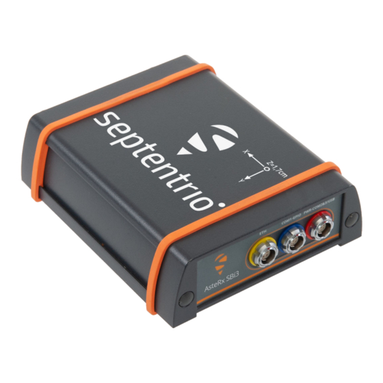
Figure 2-2: The rear panel of the AsteRx SBi3 2.4.3 Top case The AsteRx SBi3’s top of the case shows the Septentrio logo as well as the engraving of the IMU reference point, to be used for defining the antenna lever arm (see section 3.2). There is an offset of 17 mm on the Z axis (as indicated in the engraving) to be accounted for during... - Page 10 CHAPTER 2. ASTERX SBI3 OVERVIEW Figure 2-3: The top of the AsteRx SBi3...
-
Page 11: Configuring The Asterx Sbi3
7 digits of the serial number of the receiver board inside the AsteRx SBi3. This hostname can be used on a local area network to connect to the AsteRx SBi3 if the IP address assigned by the DHCP server is unknown. The hostname can be found on a sticker on the bottom of the receiver housing. -
Page 12: Connecting Via Com
Once connected, open RxControl on the computer to which the receiver is connected and follow the sequence of steps described in Figure 3-4 to open a connection to the AsteRx SBi3. Note that RxControl is part of the RxTools software suite which can be freely downloaded from the Septentrio website. -
Page 13: How To Measure And Compensate For The Antenna Lever Arm
CHAPTER 3. CONFIGURING THE ASTERX SBI3 3.2 How to measure and compensate for the Antenna Lever Arm The antenna lever-arm is the relative position between the IMU reference point and the GNSS Antenna Reference Point (ARP). The IMU reference point is clearly marked on the top panel of the receiver. -
Page 14: How To Compensate For Deviations In The Antenna Orientation
CHAPTER 3. CONFIGURING THE ASTERX SBI3 Figure 3-6: Setting the lever arm offsets. The External Setup page in the receiver web interface provides a visualization tool that allows users to get an idea of the relative positioning of the ARP and POI in the vehicle reference frame with given lever-arm settings. - Page 15 CHAPTER 3. CONFIGURING THE ASTERX SBI3 Figure 3-7: Setting the attitude offset. In many cases the antenna baseline will not align perfectly with the vehicle’s longitudinal axis or its perpendicular and in these circumstances the provided attitude offset value can also be used to compensate for small angular deviations.
- Page 16 CHAPTER 3. CONFIGURING THE ASTERX SBI3 Figure 3-8: Examples of a number of antenna setups and the corresponding heading offsets. a.) The default setup for which the angle between the antenna baseline and the longitudinal axis is 0 and no heading offset needs to be set. b.) a slight deviation (5Âř) from the longitudinal axis in the clockwise direction is reflected...
-
Page 17: How To Compensate Alternative Imu/Receiver Orientations
CHAPTER 3. CONFIGURING THE ASTERX SBI3 Figure 3-9: Visual representation of the effect of vertical offset between the two antennas on the Pitch offset. Assuming the default antenna configuration, the aux antenna being mounted higher will result in a positive value for the pitch. - Page 18 CHAPTER 3. CONFIGURING THE ASTERX SBI3 Figure 3-10: Setting the IMU orientation. Examples of typical receiver installations in a vehicle frame are given in Figure 3-11.
- Page 19 CHAPTER 3. CONFIGURING THE ASTERX SBI3 Figure 3-11: Examples illustrating the orientation of the IMU reference frame with the associated IMU orientation for the depicted installation.
-
Page 20: How To See If The Imu Is Outputting Data
External Sensor Setup page where the data stream connection is indicated and the raw sensor data can be visualized. When the IMU is communicating to the GNSS receiver, there should be a line visible between the AsteRx SBi3 and SPI as shown in Figure 3-12. - Page 21 CHAPTER 3. CONFIGURING THE ASTERX SBI3 Figure 3-13: Checking the IMU view in RxControl provides an unambiguous way of checking whether ot not the IMU is outputting data...
-
Page 22: Vehicle Velocity Input
CHAPTER 3. CONFIGURING THE ASTERX SBI3 3.6 Vehicle velocity input The AsteRx SBi3 can receive vehicle velocity information and use it as part of the integrated position. The use of the vehicle velocity it is not required for the function of the device. -
Page 23: Common Receiver Operations
SBF and NMEA can also be logged on the internal 16 GB disk of the AsteRx SBi3 Pro+. Section 4.2.1 and 4.3 detail how to log data on the receiver and how to download data logged on the receiver. - Page 24 CHAPTER 4. COMMON RECEIVER OPERATIONS Step 2: Configure data output NMEA In the NMEA/SBF Out tab, clicking on New NMEA Stream will guide you through the steps needed to configure NMEA output as shown in Figures 4-2 and 4-3. Figure 4-2: Selecting to output NMEA data on COM3 Figure 4-3: Selecting to output the GGA and ZDA NMEA message every second...
- Page 25 CHAPTER 4. COMMON RECEIVER OPERATIONS By clicking New SBF stream in the NMEA/SBF Out window, a second output stream can be configured. In the example shown in Figures 4-4 and 4-5 the PVTCartesian SBF data block will be output over COM1 once per second. Figure 4-4: Selecting to output SBF data on COM1 Figure 4-5: Selecting to output the PVTCartesian SBF block every second...
- Page 26 CHAPTER 4. COMMON RECEIVER OPERATIONS Step 3: Verifying the configuration Having configured the data output and clicked on Ok, the NMEA/SBF Out page will now display a summary of all data output as shown in Figure 4-6. Figure 4-6: Summary of all configured data output streams Figure 4-7 shows the actual data output.
-
Page 27: Output Over Ethernet
CHAPTER 4. COMMON RECEIVER OPERATIONS 4.1.2 Output over Ethernet SBF and NMEA data can be sent over an Ethernet connection from the AsteRx SBi3. Step 1: Configure an IP connection on the AsteRx SBi3 The Ethernet port settings can be configured by selecting IP Ports from the Communication menu. - Page 28 CHAPTER 4. COMMON RECEIVER OPERATIONS Step 2: Configure output of NMEA messages In the NMEA/SBF Out window, click on New NMEA stream and follow the sequence of windows to configure the data you want to output. In the example shown in Figure 4-9, the NMEA GGA message will be output every second.
- Page 29 CHAPTER 4. COMMON RECEIVER OPERATIONS Step 3: Configure Data Link to listen for NMEA output The screenshots in Figure 4-10 show how the Septentrio GUI tool Data Link can be configured to listen for the AsteRx SBi3 GGA output. Click on the TCP/IP Client button to configure the connection. In the highlighted fields insert the IP address or hostname of the receiver and the port number configured in Step 1.
- Page 30 CHAPTER 4. COMMON RECEIVER OPERATIONS Figure 4-11: The Show data window of Data Link showing the NMEA GGA message coming from the AsteRx SBi...
-
Page 31: How To Log Data
CHAPTER 4. COMMON RECEIVER OPERATIONS 4.2 How to log data The AsteRx SBi3 Pro+ has 16 GB of memory for internal data logging. 4.2.1 Internal logging Step 1: Defining the Disk Full action When setting up a logging session for the first time, it is a good idea to define what you would like to happen when the internal memory is full. - Page 32 CHAPTER 4. COMMON RECEIVER OPERATIONS Step 2: Configuring a logging session To define a new logging session, press New NMEA Stream or New SBF Stream as shown in Figure 4-13. Figure 4-13: Defining a new logging session You can then follow the sequence of steps shown in Figure 4-14, selecting the various configuration settings for the logging session.
- Page 33 CHAPTER 4. COMMON RECEIVER OPERATIONS Figure 4-14: Follow the sequence of windows to fully configure the logging session Step 3: Verifying the configuration When you have finished configuring the logging session, the Log Sessions window will show a summary of the defined logging sessions as in Figure 4-15. An estimate of the daily size of data generated with the current logging configuration is also given.
-
Page 34: Downloading Logged Data From The Receiver
Data files logged by the AsteRx SBi3 Pro+ can be downloaded using the web interface using the Disk Contents tab on the main page of the Logging menu. Individual files can be downloaded by clicking on the green download arrow next to the file name as shown... -
Page 35: Appendix A Rear-Panel Port Descriptions
APPENDIX A. REAR-PANEL PORT DESCRIPTIONS A Rear-panel port descriptions A.1 PWR-COM2&3/USB Figure A-1: Solder view of the 7-pin female PWR-COM2&3/USB socket on the rear panel of the AsteRx SBi3 The 7-pin connector type is an ODU MINI-SNAP F Circular Connector Series S40F1C-P07MCD0-500S. PIN #... -
Page 36: Com1-Gpio
APPENDIX A. REAR-PANEL PORT DESCRIPTIONS A.2 COM1-GPIO Figure A-2: Solder view of the 7-pin female COM1-GPIO socket on the rear panel of the AsteRx SBi3 The 7-pin connector type is an ODU MINI-SNAP F Circular Connector Series S40F1C-P07MCD0-500S. PIN #... -
Page 37: Eth
A.3 ETH Figure A-3: Solder view of the 4-pin female ETH socket on the rear panel of the AsteRx SBi3 The 4-pin connector type is an ODU MINI-SNAP F Circular Connector Series S40F1C-P04MFG0-50OO. PIN # Name Description Ethernet TX+ Ethernet TX-... - Page 38 APPENDIX A. REAR-PANEL PORT DESCRIPTIONS...
Need help?
Do you have a question about the AsteRx SBi3 and is the answer not in the manual?
Questions and answers