Table of Contents
Advertisement
Advertisement
Table of Contents

Related Manuals for SEPTENTRIO AsteRx-U3


Summary of Contents for SEPTENTRIO AsteRx-U3
- Page 1 AsteRx-U3 User Manual...
- Page 2 June 17, 2022 Thank you for choosing the AsteRx-U3! This user manual provides detailed instructions on how to use AsteRx-U3 and we recommend that you read it carefully before you start using the device. Please note that this manual provides descriptions of all functionalities of the AsteRx-U3 product family however, the particular AsteRx-U3 you purchased may not support functions specific to certain variants.
-
Page 3: Table Of Contents
RTK ......... . 34 OW TO CONFIGURE THE 4.1.1 How to configure the AsteRx-U3 in RTK rover mode using the UHF radio 34 4.1.2 How to configure the AsteRx-U3 in RTK rover mode using the cellular modem and NTRIP . - Page 4 CONTENTS ........46 OW TO CONFIGURE THE TTITUDE .
-
Page 5: Introduction
1 Introduction 1.1 User Notices 1.1.1 CE Notice AsteRx-U3 receivers carry the CE mark and are as such compliant with the 2014/53/EU - Radio Equipment Directive (RED), 2011/65/EU - Restriction of Hazardous Substances (RoHS) Directive and 93/68/EC - CE-marking Directive. -
Page 6: Support
The device should be installed in a restricted access area and used by skilled or instructed personnel. 1.1.4 Support For first-line support please contact your AsteRx-U3 dealer. Further information can be found on our website or by contacting Septentrio Technical Support. http://www.septentrio.com... -
Page 7: Asterx-U3 Overview
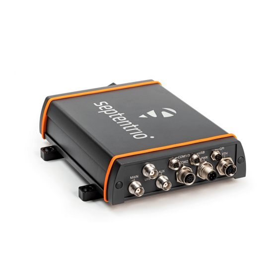
The AsteRx-U3 provides multi-frequency, multi-constellation GNSS positioning capability together with GNSS Heading and wireless communication options within a rugged IP68 housing for the broadest range of applications. AsteRx-U3 can be easily monitored and configured without any special software via the built-in web user interface accessible via WiFi, Ethernet or USB connection. -
Page 8: Physical And Environmental
2.1. ASTERX-U3 KEY FEATURES 2.1.2 Physical and Environmental Size: 157 x 200 x 50 mm (not including brackets and connectors) Size: 183 x 242 x 56 mm (including brackets and connectors) Weight: 1.1 kg Input voltage: 9-48 V DC Power consumption:... -
Page 9: Asterx-U3 Variants
2.2. ASTERX-U3 VARIANTS 2.2 AsteRx-U3 variants The AsteRx-U3 is available in multiple variants: Variant Main features (Part number) AsteRx-U3 • Dual antenna GNSS receiver ANNNNR AsteRx-U3 • Dual antenna GNSS receiver ANNUNR • Integrated UHF modem • Dual antenna GNSS receiver AsteRx-U3 •... -
Page 10: Asterx-U3 Design
2.3. ASTERX-U3 DESIGN 2.3 AsteRx-U3 design 2.3.1 Front panel The front-panel layout of the AsteRx-U3 integrating Bluetooth/Wi-Fi and Cellular antenna connectors is shown in Figure 2-1. Depending on the configuration, some connectors may be present or not on the device. -
Page 11: Led Description
2.3. ASTERX-U3 DESIGN 2.3.2 LED description Icon Behavior Off: Bluetooth disabled On: Bluetooth connected blue Blinking slowly: Not connected but discoverable Off: WiFi disabled On: Access-point mode or client mode Blinking slowly: Establishing a connection in client mode green Blinking quickly: Error, not connected Off: Not logging... -
Page 12: Rear Panel
Important: Only insert or remove the SIM card while the unit is powered down. AsteRx-U3 accepts a nano SIM (4FF), required for the operation of the integrated cellular modem. The SIM card can be inserted into the SIM connector in the front panel of the AsteRx-U3 as shown in Figure 2-3. -
Page 13: Mounting Brackets
Figure 2-3: SIM card slot on the AsteRx-U3 2.3.5 Mounting brackets The AsteRx-U3 is supplied with mounting brackets for fixing the unit using 4 bolts. The size of the fixing bolts can be M6 or smaller and the distance between the holes is shown in Figure 2-4. - Page 14 2.3. ASTERX-U3 DESIGN Figure 2-4: Mounting brackets fitted to the AsteRx-U3...
-
Page 15: Internal Memory
2.3. ASTERX-U3 DESIGN 2.3.6 Internal memory The AsteRx-U3 has 16 GB of internal memory for data logging. Data can be logged in SBF or NMEA format and may be retrieved via the logging tab of the web interface. -
Page 16: Shipping Box Contents
2.4. SHIPPING BOX CONTENTS 2.4 Shipping box contents 2.4.1 Supplied as standard The following items with their part numbers are supplied as standard with AsteRx-U3. 2.4.2 Optional items The following accessories can be ordered with AsteRx-U3. Figure 2-6: Power cable, M12 to DC jack 5.5mmx2.1mm, 1.3m (216203) - Page 17 2.4. SHIPPING BOX CONTENTS Figure 2-10: PPS Cable, M12 to 1 x BNC male, 1.5m (216206) Figure 2-11: COM1 Serial Cable, M8 to DB9 female, 1.8m (216208) Figure 2-12: COM1 and COM3 Serial Cable, M8 to 2x DB9 female, 1.8m (216209) Figure 2-13: CAN and Event Cable, M8 unterminated, 3m (216210) Figure 2-14: Power cable, M12 unterminated, 3m (216214)
-
Page 18: Quick Start
Using a power cable, the receiver can be powered by applying 9 to 48 V via the power-in wire. The power socket is indicated in Figure 3-1. Figure 3-1: Rear panel power socket AsteRx-U3 can also use Power over Ethernet, 802.3af mode A (37-57 VDC) by using the ETH socket. Figure 3-2: Rear panel ETH socket The AsteRx-U3 does not have a power button and the unit will power up automatically when power is applied. -
Page 19: Connecting An Antenna
The following sections describe each of the connection methods. 3.3.1 Using the USB cable Connect the USB cable to the connector labeled ’USB’ on the rear panel of the AsteRx-U3 and indicated in Figure 3-4. Figure 3-4: Rear panel USB socket The first time that the USB cable is connected to a device, you may be prompted to allow... - Page 20 The USB connection on the AsteRx-U3 functions as network adapter and the DHCP server running on the receiver will always assign the AsteRx-U3 the IP address 192.168.3.1. To connect to the AsteRx-U3, you can then simply open a web browser using the IP address 192.168.3.1 as shown in Figure 3-6.
-
Page 21: Using The Ethernet Cable
By default, the AsteRx-U3 has the hostname ‘http://AsteRx-U3-xxxxxxx’, where xxxxxxx are the last 7 digits of the AsteRx-U3 serial number. This hostname can be used on a local area network to connect to the AsteRx-U3 if the IP address assigned by the DHCP server is unknown. -
Page 22: How To Configure Sbf And Nmea Output
3.4.1 Output over a serial COM connection The AsteRx-U3 can be connected via a serial COM cable to an RS-232 compatible secondary device. Step 1: Configure the serial COM port The COM port of the AsteRx-U3 should be configured with the same baud rate and... - Page 23 3.4. HOW TO CONFIGURE SBF AND NMEA OUTPUT Step 2: Configure data output NMEA In the ‘NMEA/SBF Out’ tab, clicking on ‘New NMEA Stream’ will guide you through the steps needed to configure NMEA output as shown in Figures 3-10 and 3-11. Figure 3-10: Selecting to output NMEA data on COM3 Figure 3-11: Selecting to output the GGA NMEA message every second...
- Page 24 3.4. HOW TO CONFIGURE SBF AND NMEA OUTPUT By clicking ‘New SBF stream’, a second output stream can be configured. In the example shown in Figures 3-12 and 3-13 the PVTCartesian SBF data block will be output over COM1 once per second. Figure 3-12: Selecting to output SBF data on COM1...
- Page 25 3.4. HOW TO CONFIGURE SBF AND NMEA OUTPUT Figure 3-13: Selecting to output the PVTCartesian SBF block every second...
- Page 26 3.4. HOW TO CONFIGURE SBF AND NMEA OUTPUT Step 3: Verifying the configuration Having configured data output and clicked on ‘Ok’ the ‘NMEA/SBF Out’ page will now display a summary of all data output as shown in Figure 3-14. Figure 3-14: Summary of all configured data output streams Figure 3-15 shows the actual data output.
-
Page 27: Output Over Ethernet
3.4. HOW TO CONFIGURE SBF AND NMEA OUTPUT 3.4.2 Output over Ethernet SBF and NMEA data can be sent over an Ethernet connection to the AsteRx-U3. Step 1: Configure an IP connection on the AsteRx-U3 The Ethernet port settings can be configured by selecting ‘IP Ports’ from the Communication menu. - Page 28 3.4. HOW TO CONFIGURE SBF AND NMEA OUTPUT Step 2: Configure output of NMEA messages In the NMEA/SBF Out window, click on ‘New NMEA stream’ and follow the sequence of windows to configure the data you want to output. In the example shown in Figure 3-17, the NMEA GGA message will be output every second.
- Page 29 3.4. HOW TO CONFIGURE SBF AND NMEA OUTPUT Step 3: Configure Data Link to listen for NMEA output The screenshots in Figure 3-18 show how the Septentrio GUI tool Data Link can be configured to listen for the AsteRx-U3 GGA output.
- Page 30 3.4. HOW TO CONFIGURE SBF AND NMEA OUTPUT Figure 3-19: The ‘Show data’ window of Data Link showing GGA from the AsteRx-U3...
-
Page 31: How To Configure Can Output
3.5. HOW TO CONFIGURE CAN OUTPUT 3.5 How to configure CAN output The CAN implementation in the AsteRx-U3 allows the transmission of several messages, as specified below. To configure CAN using the web interface, go to the Communication menu and select CAN. -
Page 32: Supported Nmea2000 And J1939 Can Messages
Supported intervals are again 50ms, 100ms, 200ms, 500ms or 1s. Figure 3-23: J1939 PGN configuration 3.5.1 Supported NMEA2000 J1939 messages Septentrio receivers which support the CAN bus interface are able to output the NMEA2000 messages listed below: Description Max. update rate PGN129029 NMEA2000 GNSS Position... - Page 33 3.5. HOW TO CONFIGURE CAN OUTPUT Figure 3-24: Calculating position and altitude with high update rate Apart from the NMEA2000 messages listed earlier, the receiver also supports a number of proprietary messages. It should be noted that due to the restrictive nature of the NMEA2000 format, these messages follow the SAE J1939 standard.
-
Page 34: Rover Operation
UHF radio When GSM/GPRS network coverage is either sparse or unreliable, RTK correction data can be transmitted over UHF radio. The AsteRx-U3 has a built-in Satel radio modem that can be used to both receive and transmit data. - Page 35 4.1. HOW TO CONFIGURE THE ASTERX-U3 FOR RTK Step 2: Configure the UHF radio To configure the AsteRx-U3 to receive differential correction data from a remote base station, the internal UHF radio should first be powered on as shown in Figure 4-2.
- Page 36 4.1. HOW TO CONFIGURE THE ASTERX-U3 FOR RTK Step 3: Verifying the configuration If the UHF radio of the AsteRx-U3 has been correctly configured then you should see in the UHF/DiffCorr field, the grayed-out connection line is now replaced by a ‘live’ green line as shown in Figure 4-3.
-
Page 37: How To Configure The Asterx-U3 In Rtk Rover Mode Using The Cellular
4.1. HOW TO CONFIGURE THE ASTERX-U3 FOR RTK 4.1.2 How to configure the AsteRx-U3 in RTK rover mode using the cellular modem and NTRIP Step 1: Enable RTK mode Ensure that RTK is be enabled as a positioning mode. This can be done in the GNSS, Position tab by checking the ‘RTK’... - Page 38 4.1. HOW TO CONFIGURE THE ASTERX-U3 FOR RTK Step 2: Configure the cellular modem Insert a SIM card into the front-panel slot of the AsteRx-U3 as shown in Figure 2-3 while the unit is powered down. The on-board cellular modem of the AsteRx-U3 can be configured in the Communication, Cellular window as shown in Figure 4-5.
- Page 39 4.1. HOW TO CONFIGURE THE ASTERX-U3 FOR RTK Figure 4-6: Correctly configured cellular modem...
- Page 40 Using a cellular connection, you can get RTK correction data from an NTRIP service. Figure 4-7 shows the settings required to retrieve correction data from the Septentrio NTRIP Caster. Select ‘Client’ from the drop-down Mode menu. The Caster, Port, User Name and Password should be provided by the NTRIP service.
- Page 41 4.1. HOW TO CONFIGURE THE ASTERX-U3 FOR RTK Figure 4-8: Details of the selected mount Point Step 4: Verifying the configuration When both the cellular modem and NTRIP connection have been correctly configured, the Ntrip figure in Corrections NTRIP window will indicate differential correction reception as shown in Figure 4-9 with the positioning mode icon indicating RTK fixed.
-
Page 42: How To Configure The Asterx-U3 In Rtk Rover Mode Using Tcp/Ip In A
Step 1: Configure the Base station receiver Set the Base station position as static Section 5.1 describes how to configure the AsteRx-U3 as an RTK base station. Configure the Ethernet connection and diff corr output from the Base station receiver... - Page 43 4.1. HOW TO CONFIGURE THE ASTERX-U3 FOR RTK Figure 4-10: Click on New RTCM3 output to configure RTK diff corr output over an Ethernet connection...
- Page 44 4.1. HOW TO CONFIGURE THE ASTERX-U3 FOR RTK Step 2: Configure the Rover receiver Enable RTK positioning mode on the rover receiver Ensure that RTK is enabled as a positioning mode. This can be done in the GNSS Position tab by checking the ‘RTK’...
- Page 45 4.1. HOW TO CONFIGURE THE ASTERX-U3 FOR RTK Step 3: Verifying the configuration If the Base station and rover receivers have been configured correctly then connections in the Communication Ethernet windows should appear similar to those shown in Figures 4-13 and 4-14.
-
Page 46: How To Configure The Asterx-U3 For Attitude
4.2 How to configure the AsteRx-U3 for Attitude With two antennas connected to the AsteRx-U3, the receiver can calculate Heading and either Pitch or Roll. This section details how to configure the AsteRx-U3 in a two-antenna setup. Step 1: Connect a second antenna Connect a second antenna to the rear-panel connector labeled AUX and indicated in Figure 4-15. - Page 47 4.2. HOW TO CONFIGURE THE ASTERX-U3 FOR ATTITUDE Step 2: Configure attitude settings The attitude settings of the AsteRx-U3 can be configured in the GNSS, Attitude window as shown in Figure 4-16. Figure 4-16: GNSS Attitude window when two antennas are connected GNSS Attitude field...
- Page 48 SBF output via the NMEA/SBF Out window as Figure 4-17 shows. Figure 4-17: SBF blocks containing attitude information NMEA You can output the attitude information from the AsteRx-U3 in NMEA format by selecting the standard NMEA HDT sentence or the Septentrio proprietary HRP sentence as shown in Figure 4-18.
-
Page 49: How To Output Apps Signal
4.3. HOW TO OUTPUT A PPS SIGNAL 4.3 How to output a PPS signal The AsteRx-U3 can output a PPS (Pulse-per-Second) signal that can be used for example, to synchronize a secondary device to UTC time. Step 1: Connect the PPS cable Connect the PPS_OUT cable to the rear-panel connector labelled ‘PPS GPO’... -
Page 50: Time Synchronization Using The Pps Signal
The PPS signal is an electronic pulse synchronized with GPS time clock ticks, it doesn’t itself specify time. To synchronize a device with GPS time, the AsteRx-U3 can be configured to output both a PPS signal and an NMEA ZDA sentence which contains the time. The PPS signal arrives first followed by the ZDA whose reported time corresponds to the leading edge of the... -
Page 51: Base Station Operation
Set the position as static To work as a base station, the position of the AsteRx-U3 should be set to static. If not, the AsteRx-U3 will still work as a base station however the position of the rover may show more variation. - Page 52 5.1. HOW TO CONFIGURE THE ASTERX-U3 AS AN RTK BASE STATION USING THE UHF RADIO Select the Datum of the antenna position In the Datum field, you can select the datum to which the antenna coordinates refer. The selected value is stored in the Datum field of position-related SBF blocks (e.g.
- Page 53 5.1. HOW TO CONFIGURE THE ASTERX-U3 AS AN RTK BASE STATION USING THE UHF RADIO Step 3: Configuring the UHF radio The UHF radio can be configured in the ‘UHF’ window. In the example show in Figure 5-4, the radio will transmit at a frequency of 410 MHz, channel spacing of 12.5 kHz and at a power of 100 mW .
- Page 54 5.1. HOW TO CONFIGURE THE ASTERX-U3 AS AN RTK BASE STATION USING THE UHF RADIO Step 4: Verifying the configuration If the UHF radio has been correctly configured, the transmission line in the top-panel should change to green as shown in Figure 5-5. The format of the corrections stream should also be correctly identified along with the data rate.
-
Page 55: Configuring The Asterx-U3 Ntrip Caster
The AsteRx-U3 includes a built-in NTRIP Caster that makes correction data from the AsteRx-U3 available to up to 10 NTRIP clients (or rovers) over the internet. The caster supports up to three mount points and can also broadcast correction data from a remote NTRIP server. - Page 56 Client authentication for the mount point: none - any client can connect without logging in or, basic - clients have to login with a username and password. To select a correction stream from the NTRIP server of the AsteRx-U3, select ‘No’ in the ‘Allow external server’ field Click on the ‘Local Server ...’...
- Page 57 5.2. CONFIGURING THE ASTERX-U3 NTRIP CASTER Figure 5-8: Connecting as a client to the AsteRx-U3 NTRIP Caster On the NTRIP Client side Rover receivers can connect to the NTRIP Caster by going to ‘Corrections > NTRIP’ clicking New NTRIP client and entering its IP address and Port as shown in Figure 5-9. After clicking ‘Ok’, the mount point source table will be filled and a mount point can be selected.
-
Page 58: Receiver Monitoring
6.1 Basic operational monitoring The ‘Overview’ page of the web interface in Figure 6-1 shows at a glance a summary of the AsteRx-U3’s operational status. Figure 6-1: Overview page of the web interface The main information bar at the top of the window gives some basic receiver information: receiver type, serial number and position. - Page 59 6.1. BASIC OPERATIONAL MONITORING The icons to the right of the information bar show that, in this example, the position of the receiver is fixed, the overall performance (signal quality and CPU) is Excellent (5 out of 5 bars) and the receiver is logging to the internal disk. The Corrections icon indicates that differential corrections are being sent out to a rover receiver.
-
Page 60: Aim+: Using The Spectrum Analyzer To Detect And Mitigate Interference
6.2 AIM+: Using the spectrum analyzer to detect and mitigate interference The AsteRx-U3 is equipped with a sophisticated RF interference monitoring and mitigation system (AIM+). To mitigate the effects of narrow-band interference, 3 notch filters can be configured either in auto or manual mode. These notch filters effectively remove a narrow part of the RF spectrum around the interfering signal. -
Page 61: Narrowband Interference Mitigation
6.2. AIM+: USING THE SPECTRUM ANALYZER TO DETECT AND MITIGATE INTERFERENCE 6.2.1 Narrowband interference mitigation Configuring the notch filters When the notch filters are set to their default auto mode, the receiver performs automatic interference mitigation of the region of the spectrum affected by interference. In manual mode, as shown configured for Notch1 in Figure 6-3, the region of the affected spectrum is specified by a center frequency and a bandwidth which is effectively blanked by the notch filter. -
Page 62: Wideband Interference Mitigation
There are also intentional sources of interference from devices such as chirp jammers. The wideband interference mitigation system (WBI) of the AsteRx-U3 can reduce the effect of both types of interference on GNSS signals. Configuring WBI mitigation The wideband interference mitigation system (WBI) can be enabled by selecting ‘on’... - Page 63 6.2. AIM+: USING THE SPECTRUM ANALYZER TO DETECT AND MITIGATE INTERFERENCE When WBI mitigation is enabled, the effect of the interference is dramatically reduced to the extent that, the small signal bump at the GPS L1 central frequency of 1575 MHz is clearly visible as Figure 6-7 shows.
-
Page 64: How To Log Data For Problem Diagnosis
6.3. HOW TO LOG DATA FOR PROBLEM DIAGNOSIS 6.3 How to log data for problem diagnosis If the AsteRx-U3 does not behave as expected and you need to contact Septentrio’s Support Department, it is often useful to send a short SBF data file that captures the anomalous behavior. - Page 65 Figure 6-9: The Logging window showing an active logging session Step 2: Downloading the logged SBF file To download a data file logged on the AsteRx-U3, click the download icon next to the filename on the Disk Contents tab as shown in Figure 6-10 Figure 6-10: Click the icon next to the file you want to download...
-
Page 66: Activity Logging
6.5. ACTIVITY LOGGING 6.5 Activity logging The AsteRx-U3 reports various events in the Receiver Messages window of the Admin menu that can be used to check receiver operations. The example in Figure 6-11 shows that four, 15 minute SBF files have been successfully FTP pushed to a remote location. -
Page 67: Receiver Administration Operations
AsteRx-U3 The IP settings of the AsteRx-U3 can be configured on the Ethernet window of the Web Interface. By default, the AsteRx-U is configured to use DHCP to obtain an IP address but, a static IP address can also be configured as shown in Figure 7-1. -
Page 68: How To Configure Dynamic Dns
IP address is currently assigned to it. To make use of this feature on the AsteRx-U3, you should first create an account with a Dynamic DNS provider (dyndns.org or no-ip.org) to register a hostname for your receiver. -
Page 69: How To Control Access Using The Asterx-U3 Firewall
7.3 How to control access using the AsteRx-U3 Firewall You can control access to the AsteRx-U3 using the receiver’s firewall in the Firewall window. By default, all Ethernet and WiFi ports are open as are the cellular IPS ports (i.e. those defined on the IP Ports menu). -
Page 70: How To Upgrade The Firmware Or Upload A New Permission File
The AsteRx-U3 firmware and permission files both have the extension .suf (Septentrio Upgrade Format) and can be uploaded to the AsteRx-U3 as shown in the steps below. Firmware upgrades can be downloaded from the Septentrio website and are free for the lifetime of the receiver. - Page 71 Step 2: Verifying the upgrade If there were no problems with the upgrade the message ‘Upgrade successful’ will appear. You can then check on the Admin About tab that the AsteRx-U3 firmware or permission file has correct, new version as indicated in Figure 7-7.
-
Page 72: How To Set The Asterx-U3 To Its Default Configuration
Admin > Reset tab as shown in Figure 7-9, different functionalities can be individually reset. A ‘Soft’ level reset will cause the AsteRx-U3 to boot up with its current configuration while a ‘hard’ reset will use the configuration stored in the boot file. -
Page 73: How To Copy The Configuration From One Receiver To Another
7.7 How to copy the configuration from one receiver to another In the Admin Configurations tab, the configuration of an AsteRx-U3 can be easily saved to a PC as a text file. A saved configuration can also be uploaded to an AsteRx-U3. - Page 74 7.7. HOW TO COPY THE CONFIGURATION FROM ONE RECEIVER TO ANOTHER Select the configuration file to be uploaded then click on OK on the status pop-up as shown in Figure 7-12. Figure 7-12: Select the configuration file to upload...
-
Page 75: Security
8 Security 8.1 Default access to the AsteRx-U3 You can manage the access that users have to the AsteRx-U3 in the ‘User Administration’ window of the ‘Admin’ menu. By default, all communications are assigned User-level access as shown in Figure 8-1. ‘User’... -
Page 76: User Access: An Example
8.3. USER ACCESS: AN EXAMPLE Figure 8-2: Click on ‘New user’ and fill in the user details and the default access when not logged in 8.3 User access: an example Figure 8-3: An example with two defined users In the example shown in Figure 8-3: Web Interface: Anonymous users (without password) can connect to the receiver via the web interface as Viewers. -
Page 77: Using Ssh Key Authentication
By default, anonymous users have full access over FTP, SFTP and rsync to the files logged on the AsteRx-U3. FTP, SFTP and rsync access can be limited by configuring user access, as described in Section 8.1. For added security, user authentication for SFTP and rsync access can be configured using an SSH public key. -
Page 78: Http/Https
The generated public key is the highlighted text that can be pasted directly into the SSH Key field of the AsteRx-U3 Web Interface as shown in Figure 8-6. Figure 8-6: Using an SSH Key 521-bit ECSDA keys offer the best security however, ECSDA 256 and 384-bit keys can also be used. - Page 79 8.4. HTTP/HTTPS Figure 8-7: Uploading a certificate to the receiver...
-
Page 80: Appendix
9 Appendix 9.1 Rear-panel port descriptions 9.1.1 Power (PWR) Figure 9-1: 4-pin male socket pin-numbering guide as viewed end on. PIN # Name Comment Power_IN Power input, 9 to 48 VDC Power_IN PINs 1 and 2 shorted together internally Ground Ground PINs 3 and 4 shorted together internally 9.1.2 Ethernet (ETH) -
Page 81: Usb
9.1. REAR-PANEL PORT DESCRIPTIONS 9.1.3 USB Figure 9-3: 4-pin female socket pin-numbering guide as viewed end on. PIN # Name Comment USB D+ USB 2.0 data signal positive D+ USB V USB Power. Cannot be used to power the receiver USB D- USB 2.0 data signal positive D- Ground... -
Page 82: Serial (Com1/3)
9.1. REAR-PANEL PORT DESCRIPTIONS 9.1.5 Serial (COM1/3) Figure 9-5: 6-pin female socket pin-numbering guide as viewed end on. PIN # RS232 mode RS422 mode Comment RX1- RX1+ TX1- TX1+ Reserved Reserved Ground Ground 9.1.6 Serial (COM2) Figure 9-6: 8-pin female socket pin-numbering guide as viewed end on. PIN # RS232 mode RS422 mode... -
Page 83: Uhf Radio Baud Rates
9.2. UHF RADIO BAUD RATES 9.2 UHF radio baud rates The receiver automatically adapts the baud rate according to the UHF channel bandwidth (12.5 or 25 kHz). The parameters associated with the different protocols are given in the table below. When sending correction data for multiple constellations and frequencies at rates of 1 Hz and greater, the lowest baud rate configurations (9600 and 4800 baud) may not be sufficient and you should select a protocol/bandwidth combination for 19200 baud.
Need help?
Do you have a question about the AsteRx-U3 and is the answer not in the manual?
Questions and answers