Table of Contents
Advertisement
Quick Links
Advertisement
Table of Contents

Related Manuals for SEPTENTRIO AsteRx-m2


Summary of Contents for SEPTENTRIO AsteRx-m2
- Page 1 AsteRx-m2 Product Group Hardware Manual Version 1.5.0...
- Page 2 AsteRx-m2 Product Group Hardware Manual Version 1.5.0 June 12, 2020 © Copyright 2000-2020 Septentrio nv/sa. All rights reserved. Septentrio Greenhill Campus, Interleuvenlaan 15i 3001 Leuven, Belgium http://www.septentrio.com Phone: +32 16 300 800 Fax: +32 16 221 640 @septentrio...
-
Page 3: Table Of Contents
1 Table of contents TABLE OF CONTENTS ....................3 ASTERX-M2 OEM ......................6 Mounting ........................7 Environmental ......................7 Power and Power Consumption ................7 RF Interface ......................8 2.4.1 Electrical Specifications ..................8 2.4.2 System Noise Figure and C/N0 ................9 I/O Connectors ....................... - Page 4 USB Dev ........................23 USB Host ......................... 23 3.10 REF IN ........................23 3.11 Buttons ........................23 3.12 SD Card Socket ....................... 24 APPENDIX A LED STATUS INDICATORS ................. 25 APPENDIX B EMC CONSIDERATIONS ................27...
- Page 5 ROHS/WEEE NOTICE Septentrio receivers are compliant with the latest WEEE, RoHS and REACH directives. For more info see www.septentrio.com/en/environmental-compliance. ESD PRECAUTIONS The OEM module is sensitive to electrostatic discharge (ESD). Although it has a limited protection, it should only be manipulated in an ESD-safe environment and using ESD-safe...
-
Page 6: Asterx-M2 Oem
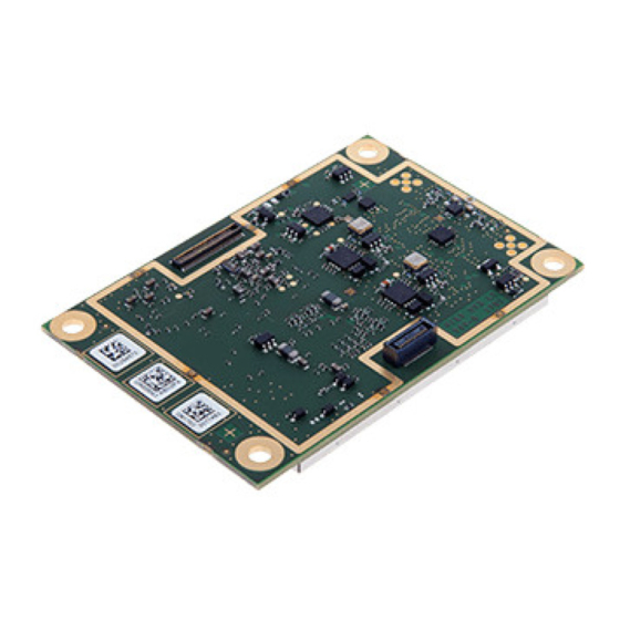
AsteRx-m2 OEM 2 AsteRx-m2 OEM All dimensions in millimeters. Weight = 28 g RF connectors (u.FL type) are mounted on top side of the PCB. The 30- and 60-pin Hirose I/O connectors are mounted on the bottom side. -
Page 7: Mounting
AsteRx-m2 OEM 2.1 Mounting The four mounting holes are compatible with M3 screws. Use M3 3.5mm spacers. An example of applicable SMD spacer is THF-1.6-3.5-M3 from MAC8. All mounting holes are grounded, and should preferably be connected to ground on the host PCB. -
Page 8: Rf Interface
Typically, the ANTA connector is to be used for internal antennas that are always connected to the AsteRx-m2, e.g. when the receiver and the antenna are integrated in the same system. The ANTB connector is to be used for external antennas that, if connected, replace the internal antenna. -
Page 9: System Noise Figure And C/N0
AsteRx-m2 OEM If pin#18 is not connected, there is no DC voltage to the antenna. ANTA DC series impedance < 2.2 Ohms ANTB DC series impedance < 4 Ohms ANTB antenna detection current 6 mA Guaranteed antenna current 200 mA... - Page 10 AsteRx-m2 OEM Note that, when connecting the receiver directly to a GNSS simulator, the applicable value for NFrx is that of a passive antenna (4.5dB), Tant=290K, NFant=0dB and Gpreamp=0dB.
-
Page 11: I/O Connectors
AsteRx-m2 OEM 2.5 I/O Connectors 60 pin 30 pin The main connector is the 30-pin connector. That connector must always be connected. The 60-pin connector provides additional signals (IO enable, serial CTS/RTS lines, GPIOs, Ethernet, 10-MHz reference input, etc). That connector can be ignored and left unconnected if these signals are not needed. -
Page 12: 30-Pin Connector
AsteRx-m2 OEM 2.5.1 30-pin Connector Connector type: Hirose 30 pins DF40HC (3.5)-30DS-0.4V(51) Mating connector: Hirose DF40C-30DP-0.4V(51) See the pin numbering convention in the above picture. Pin# Name Type Level Description Comment 3.3V Main power supply input Both Vin pins (pin#1 and pin#2) must +/-5% be tied together. -
Page 13: 60-Pin Connector
General purpose output. GP1 in setGPIOFunctionality command. See section 2.8 RTS2 LVTTL Serial COM2 RTS line. The AsteRx-m2 drives this pin low when ready to receive data. RTS3 LVTTL Serial COM3 RTS line. The AsteRx-m2 drives this pin low when ready to receive data. - Page 14 Reserved CTS2 I, K LVTTL Serial COM 2 CTS line. Must be driven low when ready to receive data from the AsteRx-m2. CTS3 I, K LVTTL Serial COM 3 CTS line. Must be driven low when ready to receive data from the AsteRx-m2.
-
Page 15: External Frequency Reference Input (Ref In)
2V and 5V, for example it can be an LVTTL clock signal. At start-up, the AsteRx-m2 checks the presence of the external frequency reference on pin#60. If a signal is present, the receiver uses that signal as primary frequency reference, instead of its internal TCXO. -
Page 16: Standby Mode
AsteRx-m2 OEM The GPx pins can drive a maximum current of 10mA. 2.9 Standby Mode In standby mode, all receiver functions are turned off and the power consumption is very low (see section 2.3). There are two ways to enter standby mode: 1. -
Page 17: Usb Interface
AsteRx-m2 OEM See instructions in the Reference Guide for details on how to configure SD card logging. The receiver is compatible with SD cards of up to 32GB. The file system is FAT32. Shortly driving the button pin (pin#25 of 30-pin connector) low toggles logging on and off. - Page 18 AsteRx-m2 OEM...
-
Page 19: Development Kit
USB Dev USB Host 3&4 REF IN The AsteRx-m2 Development Kit is specifically designed to simplify the development process for new integrations. 3.1 Header Types All headers have a pitch of 2.54mm, with the exception of J500 (PPS/EVENTS) and J501 (GP). -
Page 20: Antenna Connectors
Make sure that a jumper is placed on header J200, as shown below. Otherwise the DevKit will be powered, but not the OEM board. To measure the power consumption of the AsteRx-m2 OEM board (excluding the contribution from the DevKit and the antenna), remove the jumper on J200 and connect the two pins to the probes of a multimeter in current-sensing mode. -
Page 21: Leds And General Purpose Output Pins
The POWER LED lights when the DevKit is powered. The GPLED and LOGLED are connected to the homonymous pins of the 30-pin connector of the AsteRx-m2 board. See section 2.5.1 for the pinout, and Appendix A for a description of the LED behavior. -
Page 22: Pps Out And Event Inputs
EVENTB EVENTA The PPSout pin of header J500 is directly connected to the PPSOut pin of the AsteRx-m2 (see section 2.5.1). The PPS level is 3.3V. The EVENTA and EVENTB pins of J500 are connected to the EventA and EventB pins of the AsteRx-m2 through a buffer. -
Page 23: Ethernet
3.11 Buttons nRST LOGGING Pressing the nRST button drives the nRST pin of the AsteRx-m2 low, which resets the receiver. Pressing the LOGGING button drives the Button pin of the AsteRx-m2 low. This can be used to enabled and disable logging, as described in section 2.10. -
Page 24: Sd Card Socket
Development Kit 3.12 SD Card Socket The receiver can log files on the micro SD Card in this socket. See section 2.10 for a description of the SD Card logging. -
Page 25: Appendix Aled Status Indicators
LED Status Indicators Appendix A LED Status Indicators The LED pins can be used to monitor the receiver status. They can be used to drive external LEDs (max drive current 10mA). It is assumed that the LED lights when the electrical level of the corresponding pin is high. - Page 26 LED Status Indicators The LOGLED reports the SD card mount status and logging activity. LED Behaviour LOGLED LED is off when the SD card is not present or not mounted. LED is on when the SD card is present and mounted. Short blinks indicate logging activity.
-
Page 27: Appendix Bemc Considerations
This is where the RF spectrum monitor built in the AsteRx-m2 comes in handy. The spectrum monitor can be accessed in RxControl under the View / Spectrum View menu. The spectrum can also be monitored offline if the BBSamples SBF blocks are logged. - Page 28 EMC Considerations An example of interference is shown below. This particular interference at about 1598 MHz falls in the GLONASS L1 band and slightly degrades the L1 C/N0 of some GLONASS satellites. Try to keep personal computers and other equipment more than 2 meters away from the antenna while assessing electromagnetic compatibility of the integration.
- Page 29 (see the setNotchFiltering command). Intermittent wide-band cross-talk can often be eliminated with the wide band interference canceller (see the setWBIMitigation command). AsteRx-m2 has been designed to minimize radiation and can be used close to an antenna without additional shielding.
Need help?
Do you have a question about the AsteRx-m2 and is the answer not in the manual?
Questions and answers