Table of Contents
Advertisement
Quick Links
Advertisement
Table of Contents

Related Manuals for SEPTENTRIO AsteRx-m Series


Summary of Contents for SEPTENTRIO AsteRx-m Series
- Page 1 AsteRx-m Product Family Hardware Manual Version 3.3.0...
- Page 2 AsteRx-m Product Family Hardware Manual Version 3.3.0 December 21, 2016 © Copyright 2000-2016 Septentrio nv/sa. All rights reserved. Septentrio Greenhill Campus, Interleuvenlaan 15i 3001 Leuven, Belgium http://www.septentrio.com support@septentrio.com Phone: +32 16 300 800 Fax: +32 16 221 640 @septentrio...
-
Page 3: Table Of Contents
1 Table of contents TABLE OF CONTENTS ....................3 ASTERX-M OEM ......................7 Receiver Dimensions ....................8 Connector Types ...................... 8 Physical and Environmental .................. 9 Power Consumption ....................9 Antenna Selection ....................9 30-pin Connector ....................10 SD Memory Card Usage ..................11 Power Down ...................... - Page 4 ROHS/WEEE NOTICE Receivers of the AsteRx-m family comply with European Union (EU) Directive 2002/95/EC on the restriction of the use of certain hazardous substances in electrical and electronic equipment (RoHS Directive). Receivers of the AsteRx-m family comply with the European Union (EU) Directive 2002/96/EC on waste electrical and electronic equipment (WEEE).
- Page 5 Statement 0001/WARNING: The power supply provided by Septentrio (if any) should not be replaced by another. If you are using the receiver with your own power supply, it must have a double isolated construction and must match the specifications of the provided power supply.
- Page 6 Electronic components and assemblies, such as Septentrio OEM receivers, can be permanently damaged or destroyed when near or in contact with electro-statically charged objects. When you handle components or assemblies that are not in protective bags and you are not sure whether they are static-sensitive, assume that they are static-sensitive and handle them accordingly.
-
Page 7: Asterx-M Oem
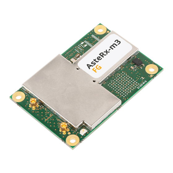
AsteRx-m OEM 2 AsteRx-m OEM Top View Internal External antenna antenna Bottom View... -
Page 8: Receiver Dimensions
AsteRx-m OEM 2.1 Receiver Dimensions All dimensions in millimeters. Mounting holes (marked A,B,C,D above): Diameter: 3.2mm Outer ring diameter: 5mm Weight: 26.7g 2.2 Connector Types RF connectors: U.FL Digital connector: 30-pin DF40C-30DS-0.4V(51). Pin 1 is indicated in the bottom view picture. -
Page 9: Physical And Environmental
AsteRx-m OEM 2.3 Physical and Environmental Input supply voltage 3.3V +/- 5% Antenna supply voltage 3-6V Maximal antenna current 200 mA per RF connector (built-in current limit) Antenna gain range External antenna input connector: 10-40dB Internal antenna input connector: 10-30dB Antenna input impedance 50 Ohms Operating Temperature Range... -
Page 10: 30-Pin Connector
AsteRx-m OEM 2.6 30-pin Connector The I/O connector is the Hirose 30 pins DF40HC(3.5)-30DS-0.4V(51) connector. The mating connector is Hirose DF40C-30DP-0.4V(51) which is available from Digikey (order number H11622CT-ND). Pin Description Pin Description 1 Vin: 3.3V +/- 5% 2 Vin: 3.3V +/- 5% 3 GND 4 GND 5 USB_D+... -
Page 11: Sd Memory Card Usage
AsteRx-m OEM LOGLED LVTTL Internal logging status indicator, see Appendix A. Leave unconnected if not used. Max output current: 8mA. Ground. All ground pins must be connected. Pin# Name Type Level Description Connection Tips 3.3V Main power supply input Both Vin pins (pin#1 and pin#2) must be tied +/-5% together. - Page 12 AsteRx-m OEM SPI1_MISO SPI1_SCK SPI1_MOSI SPI1_nCS0 The receiver is compatible with SD cards of up to 32GB. The file system is FAT32. Shortly driving the button pin (pin#25) low toggles SBF and NMEA logging on and off. Driving the button pin low for at least 5 seconds unmounts the SD card if it was mounted, or mounts it if it was unmounted.
-
Page 13: Power Down
AsteRx-m OEM 2.8 Power Down The nPDN pin (pin#20) is not functional on older board versions (versions GRB00231000AB03xx and GRB00231000AB04xx). The board version is printed on the board label. In case you need the nPDN functionality and it is not available in your particular version of the board, we recommend implementing the following circuit:... -
Page 14: Asterx-M Evaluation Board
AsteRx-m Evaluation Board 3 AsteRx-m Evaluation Board COM2 RS232 Tx Rx GND (LVTTL) GND RX3 TX3 NC GND nPDN GND evtA Reset button COM1 + PPSOut GPLED In a typical configuration, connect the USB connector to your PC using a standard USB cable, and connect your antenna to one of the antenna connectors of the AsteRx-m OEM board. - Page 15 AsteRx-m Evaluation Board The PPS Out signal (3.3V LVTTL) is available from pin#9 of the subD-9 connector. The DC voltage at the antenna connectors is set to 3.3V.
-
Page 16: Asterx-M Uas
AsteRx-m UAS 4 AsteRx-m UAS The AsteRx-m UAS consists of an AsteRx-m receiver board mounted on an interface card specifically designed for easy integration in UAS (Unmanned Aerial Systems) and mobile mapping applications. This chapter provides information on the interface card only. Refer to chapter 2 for the specifications of the AsteRx-m receiver board. -
Page 17: Connectors
AsteRx-m UAS 4.1 Connectors Type Description Usage Example 30-pin DF40C Connector to the AsteRx-m board Micro B USB USB interface to AsteRx-m Connect to laptop or PC to power the board and control the AsteRx-m. DF13-6P-1.25DSA COM1 TTL UART from AsteRx-m. Connect to the GPS-port of a Pixhawk Pin#1 is a 5V power input (compatible with standard Pixhawk cables) -
Page 18: Leds
AsteRx-m UAS 4.3 LEDs The PWR LED is lit if the interface card is powered and the supply voltage after the diode selector is above 4V. Refer to Appendix A for a description of the LOG and PVT LEDs. 4.4 Temperature Range The interface board operates in the same temperature range as the AsteRx-m receiver (-40 to 85°C). - Page 19 AsteRx-m UAS...
-
Page 20: Appendix Aled Status Indicators
LED Status Indicators Appendix A LED Status Indicators The LED pins report the status of key processes inside the receiver. They can be used to drive external LEDs (max drive current 8mA). It is assumed that the LED lights when the electrical level of the corresponding pin is high. - Page 21 LED Status Indicators The LOGLED reports the SD card mount status and logging activity. LED Behaviour LOGLED LED is off when the external SD card is not present or not mounted. LED is on when the SD card is present and mounted. Short blinks indicate logging activity.
Need help?
Do you have a question about the AsteRx-m Series and is the answer not in the manual?
Questions and answers