Table of Contents
Advertisement
Advertisement
Table of Contents

Related Manuals for SEPTENTRIO AsteRx SB3


Summary of Contents for SEPTENTRIO AsteRx SB3
- Page 1 AsteRx SB3 User Manual...
- Page 2 February 18, 2022 Thank you for choosing the AsteRx SB3 ! This user manual provides detailed instructions on how to use the AsteRx SB3 and we recommend that you read it carefully before you start using the device. Please note that this manual provides descriptions of all functionalities of the AsteRx SB3 product family however, the particular AsteRx SB3 you purchased may not support functions specific to certain variants.
-
Page 3: Table Of Contents
3.2.1 How to configure the AsteRx SB3 in RTK rover mode via Ethernet ..13 ........15... -
Page 4: Introduction
1 Introduction 1.1 User Notices 1.1.1 CE Notice AsteRx SB3 receivers carry the CE mark and are as such compliant with the 2014/53/EU - Radio Equipment Directive (RED), 2011/65/EU - Restriction of Hazardous Substances (RoHS) Directive and 93/68/EC - CE-marking Directive. -
Page 5: Safety Information
CHAPTER 1. INTRODUCTION 1.1.3 Safety information Statement 1: The power supply provided by Septentrio (if any) should not be replaced by another. If you are using the receiver with your own power supply, it must have a double isolated construction and must match the specifications of the provided power supply. -
Page 6: Support
Guide and the latest officially supported Firmware version are readily available for download. In case the AsteRx SB3 does not behave as expected and you need to contact Septentrio’s Technical Support department, you should attach a short SBF log file containing the support blocks and a Diagnostic Report of the receiver. -
Page 7: Asterx Sb3 Overview
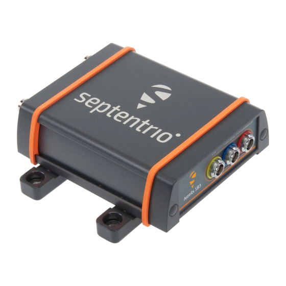
GNSS solution is ideal for rapid integration into machine control or safety applications. The AsteRx SB3 is designed to be used as a dual antenna GNSS receiver for a wide array of different systems but it can also be used as a single antenna receiver for systems which do not require heading. -
Page 8: Asterx Sb3 Design
CHAPTER 2. ASTERX SB3 OVERVIEW 2.2 AsteRx SB3 design 2.2.1 Front Panel The AsteRx SB3 ’s front panel features the two antenna TNC connectors for the Main and Aux antennas. Figure 2-1: The front panel of the AsteRx SB3 2.2.2 Rear Panel Figure 2-2 shows the layout of the rear-panel connectors of the AsteRx SB3 . -
Page 9: Configuring The Asterx Sb3
3.1.1 Powering the AsteRx SB3 The AsteRx SB3 can be powered in a number of different ways. The first method is to power the receiver by supplying 5 to 36 VDC via the open-ended power cable connected to PIN 1 of the rear-panel 7-pin female PWR-COM2&3/USB socket. -
Page 10: Connecting To The Web Interface Via Ethernet
7 digits of the serial number of the receiver board inside the AsteRx SB3 . This hostname can be used on a local area network to connect to the AsteRx SB3 if the IP address assigned by the DHCP server is unknown. The hostname can be found on a sticker on the bottom of the receiver housing. -
Page 11: Connecting To The Web Interface Via Usb
Step 2: Open a web browser and connect to the AsteRx SB3 Once connected via USB, the AsteRx SB3 can be reached using the default Ethernet-over-USB IP address 192.168.3.1 as shown in Figure 3-5. Note that this address cannot be changed. -
Page 12: Connecting Via Com
Once connected, open RxControl on the computer to which the receiver is connected and follow the sequence of steps described in Figure 3-7 to open a connection to the AsteRx SB3 . Note that RxControl is part of the RxTools software suite which can be freely downloaded from the Septentrio website. -
Page 13: How To Configure The Asterx Sb3 In Rtk Rover Mode Via Ethernet
3.2 How to configure the AsteRx SB3 for RTK The AsteRx SB3 can use correction data to calculate a cm-level RTK position. The AsteRx SB3 can obtain this correction data in several ways: over the internet via NTRIP, using a serial or USB connection or via Ethernet. - Page 14 CHAPTER 3. CONFIGURING THE ASTERX SB3 Figure 3-9: In the IP Ports window, click on New IP Receive Connection to configure the connection with the base station Step 3: Verifying the configuration If the Base station and rover receivers have been configured correctly then the Communication Ethernet window should appear similar to the window shown in 3-10.
- Page 15 3.3 How to configure the AsteRx SB3 for Attitude With two antennas connected to the AsteRx SB3 , the receiver can calculate Heading and either Pitch or Roll. This section details how to configure the AsteRx SB3 in a two-antenna setup. Step 1: Connect a second antenna Connect a second antenna to the front panel connector labelled AUX ANT as indicated in Figure 3-11.
- Page 16 CHAPTER 3. CONFIGURING THE ASTERX SB3 Figure 3-12: GNSS Attitude window when two antennas are connected GNSS Attitude field The recommended settings for a Heading setup are MultiAntenna mode with attitude calculated using Fixed ambiguities as shown. These settings are configured by default.
- Page 17 CHAPTER 3. CONFIGURING THE ASTERX SB3 Antenna Location and Antenna Offset The AsteRx SB3 assumes that the main and auxiliary antennas are placed along the longitudinal axis of the vehicle with the auxiliary in front of the main antenna. If the antennas cannot be placed in such a configuration, the reported heading and pitch may be biased.
- Page 18 CHAPTER 3. CONFIGURING THE ASTERX SB3 may not be exactly at the same height in the vehicle reference frame. Since pitch is defined as the right-handed rotation about the vehicle Y axis, a situation where the main antenna is mounted lower than the aux antenna (assuming the default antenna setup) will result in a positive pitch a shown in Figure 3-14.
- Page 19 SBF output via the NMEA/SBF Out window as Figure 3-15 shows. Figure 3-15: SBF blocks containing attitude information NMEA You can output the attitude information from the AsteRx SB3 in NMEA format by selecting the standard NMEA HDT sentence or the Septentrio proprietary HRP sentence as shown in Figure 3-16.
- Page 20 Set the Base station position as static To work as a Base station, the position of the AsteRx SB3 should be set to static. The Static position mode can be selected in the GNSS tab as shown in Figure 3-17.
- Page 21 CHAPTER 3. CONFIGURING THE ASTERX SB3 Click OK to apply the new settings Figure 3-18: Setting the static position to the pre-set ‘Geodetic1’ position...
- Page 22 CHAPTER 3. CONFIGURING THE ASTERX SB3 Set Marker/Station name A Marker name and Station code can also be defined through the GNSS/Name and Marker menu as shown in Figure 3-19. Figure 3-19: Setting the Station settings Step 2: Configure the internet connection An internet connection can be achieved by using the Ethernet connector or the USB connector of the AsteRx SB3 .
- Page 23 SB3 available to up to 10 NTRIP clients over the internet. The caster supports up to three mount points and can also broadcast correction data from a remote NTRIP server. All settings relating to the AsteRx SB3 NTRIP Caster can be configured on the NTRIP Caster window from the Communication menu.
- Page 24 CHAPTER 3. CONFIGURING THE ASTERX SB3 Click on the Configure Output ... button to enable the local NTRIP server of the AsteRx SB3 and to select the individual messages you want to broadcast. By default, RTK correction messages necessary for GPS, GLONASS, Galileo and BeiDou are pre-selected. Click Ok to apply the settings.
- Page 25 If the client receivers are configured to send a GGA message to the caster (as was the case in Figure 3-23), then their position will also be visible. Figure 3-22: Connecting as a client to the AsteRx SB3 NTRIP Caster On the NTRIP Client side Rover receivers can connect to the NTRIP Caster by entering its IP address and Port as shown in Figure 3-23.
- Page 26 CHAPTER 3. CONFIGURING THE ASTERX SB3 Step 3b: Configure the output of differential corrections using a TCP/IP in a closed network Configure the IPS connection Setup an IPS connection over which the differential corrections can be streamed. On the IP Ports page, click on New IP Server as shown in Figure 3-24, then insert the port number and mode of the connection.
- Page 27 CHAPTER 3. CONFIGURING THE ASTERX SB3 Configure the correction stream On the Corrections Output window, click on New RTCM3 output as shown in Figure 3-25. You can then select the IPS connection configured in the previous step. The messages necessary for RTK and DGNSS (for GPS, GLONASS, Galileo and BeiDou) are selected by default but you can select any combination of correction messages that you want to output.
- Page 28 Having configured the settings and clicked Ok to apply them, you can now connect to the configured Ethernet port of the AsteRx SB3 using a terminal emulator tool such as Data Link The Ethernet IP address is IP address shown under Ethernet Status on Communication >...
- Page 29 CHAPTER 3. CONFIGURING THE ASTERX SB3 Figure 3-27: The RTCMv3 differential correction stream output from the IPS1 Ethernet connection of the AsteRx SB3 When a connection to the configured Ethernet port has been established, in this example using Data Link, the Data Streams field on the Corrections Output window should now show the active blue connection shown in Figure 3-28 and the corrections output icon in the information panel should appear active.
-
Page 30: Common Receiver Operations
SBF and NMEA can also be logged on the internal 16 GB disk of the AsteRx SB3 . Section 4.2.1 and 4.3 detail how to log data on the receiver and how to download data logged on the receiver. - Page 31 CHAPTER 4. COMMON RECEIVER OPERATIONS Step 2: Configure data output NMEA In the NMEA/SBF Out tab, clicking on New NMEA Stream will guide you through the steps needed to configure NMEA output as shown in Figures 4-2 and 4-3. Figure 4-2: Selecting to output NMEA data on COM3 Figure 4-3: Selecting to output the GGA and ZDA NMEA message every second...
- Page 32 CHAPTER 4. COMMON RECEIVER OPERATIONS By clicking New SBF stream in the NMEA/SBF Out window, a second output stream can be configured. In the example shown in Figures 4-4 and 4-5 the PVTCartesian SBF data block will be output over COM1 once per second. Figure 4-4: Selecting to output SBF data on COM1 Figure 4-5: Selecting to output the PVTCartesian SBF block every second...
- Page 33 CHAPTER 4. COMMON RECEIVER OPERATIONS Step 3: Verifying the configuration Having configured the data output and clicked on Ok, the NMEA/SBF Out page will now display a summary of all data output as shown in Figure 4-6. Figure 4-6: Summary of all configured data output streams Figure 4-7 shows the actual data output.
-
Page 34: Output Over Ethernet
CHAPTER 4. COMMON RECEIVER OPERATIONS 4.1.2 Output over Ethernet SBF and NMEA data can be sent over an Ethernet connection from the AsteRx SB3 . Step 1: Configure an IP connection on the AsteRx SB3 The Ethernet port settings can be configured by selecting IP Ports from the Communication menu. - Page 35 CHAPTER 4. COMMON RECEIVER OPERATIONS Step 2: Configure output of NMEA messages In the NMEA/SBF Out window, click on New NMEA stream and follow the sequence of windows to configure the data you want to output. In the example shown in Figure 4-9, the NMEA GGA message will be output every second.
- Page 36 CHAPTER 4. COMMON RECEIVER OPERATIONS Step 3: Configure Data Link to listen for NMEA output The screenshots in Figure 4-10 show how the Septentrio GUI tool Data Link can be configured to listen for the AsteRx SB3 GGA output. Click on the TCP/IP Client button to configure the connection. In the highlighted fields insert the IP address or hostname of the receiver and the port number configured in Step 1.
- Page 37 CHAPTER 4. COMMON RECEIVER OPERATIONS Figure 4-11: The Show data window of Data Link showing the NMEA GGA message coming from the AsteRx SB3...
-
Page 38: How To Log Data
CHAPTER 4. COMMON RECEIVER OPERATIONS 4.2 How to log data The AsteRx SB3 has 16 GB of memory for internal data logging. 4.2.1 Internal logging Step 1: Defining the Disk Full action When setting up a logging session for the first time, it is a good idea to define what you would like to happen when the internal memory is full. - Page 39 CHAPTER 4. COMMON RECEIVER OPERATIONS Step 2: Configuring a logging session To define a new logging session, press New NMEA Stream or New SBF Stream as shown in Figure 4-13. Figure 4-13: Defining a new logging session You can then follow the sequence of steps shown in Figure 4-14, selecting the various configuration settings for the logging session.
- Page 40 CHAPTER 4. COMMON RECEIVER OPERATIONS Figure 4-14: Follow the sequence of windows to fully configure the logging session Step 3: Verifying the configuration When you have finished configuring the logging session, the Log Sessions window will show a summary of the defined logging sessions as in Figure 4-15. An estimate of the daily size of data generated with the current logging configuration is also given.
- Page 41 Data files logged by the AsteRx SB3 can be downloaded using the web interface using the Disk Contents tab on the main page of the Logging menu. Individual files can be downloaded by clicking on the green download arrow next to the file name as shown...
-
Page 42: Appendix A Rear-Panel Port Descriptions
A Rear-panel port descriptions A.1 PWR-COM2&3/USB Figure A-1: Solder view of the 7-pin female PWR-COM2&3/USB socket on the rear panel of the AsteRx SB3 The 7-pin connector type is an ODU MINI-SNAP F Circular Connector Series S40F1C-P07MCD0-500S. PIN # Colour... -
Page 43: Com1-Gpio
APPENDIX A. REAR-PANEL PORT DESCRIPTIONS A.2 COM1-GPIO Figure A-2: Solder view of the 7-pin female COM1-GPIO socket on the rear panel of the AsteRx SB3 The 7-pin connector type is an ODU MINI-SNAP F Circular Connector Series S40F1C-P07MCD0-500S. PIN #... -
Page 44: Eth
A.3 ETH Figure A-3: Solder view of the 4-pin female ETH socket on the rear panel of the AsteRx SB3 The 4-pin connector type is an ODU MINI-SNAP F Circular Connector Series S40F1C-P04MFG0-50OO. PIN # Name Description Ethernet TX+ Ethernet TX-... - Page 45 APPENDIX A. REAR-PANEL PORT DESCRIPTIONS...
Need help?
Do you have a question about the AsteRx SB3 and is the answer not in the manual?
Questions and answers