
Related Manuals for SEPTENTRIO PolaRx4 Series


Summary of Contents for SEPTENTRIO PolaRx4 Series
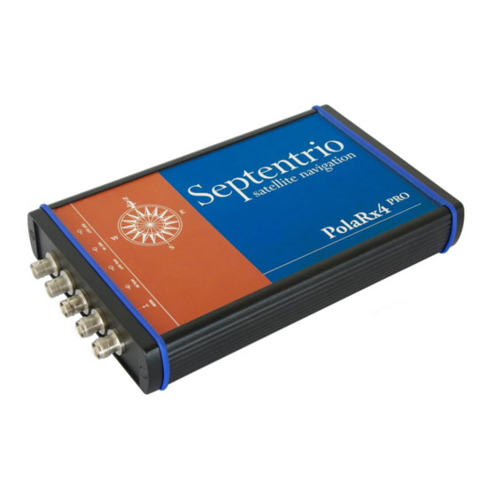
- Page 1 _______________________________________________________________________________ PolaRx4 Product Family Hardware Manual Version 2.0.0 PolaRx4 Product Family Hardware Manual v2.0.0...
- Page 2 _______________________________________________________________________________ PolaRx4 Product Family Hardware Manual Version 2.0.0 March 04, 2015 © Copyright 2000-2015 Septentrio nv/sa. All rights reserved. Septentrio Satellite Navigation Greenhill Campus, Interleuvenlaan 15G B-3001 Leuven, Belgium http://www.septentrio.com support@septentrio.com Phone: +32 16 300 800 Fax: +32 16 221 640...
-
Page 3: Table Of Contents
_______________________________________________________________________________ Table of contents TABLE OF CONTENTS ......................3 POLARX4_PRO AND POLARX4TR_PRO ..............6 Rear Panel Connectors......................6 1.1.1 MAIN (TNC) ........................6 1.1.2 PPS OUT (BNC) ......................... 7 1.1.3 REF IN (BNC) ........................7 1.1.4 REF OUT (BNC) ......................... 7 1.1.5 PPS IN (BNC) –... - Page 4 _______________________________________________________________________________ CE NOTICE PolaRx4 receivers carry the CE mark and are as such compliant with the 2004/108/EC - EMC Directive and amendments, 2006/95/EC - Low Voltage Directive, both amended by the CE-marking directive 93/68/EC. With regards to EMC, these devices are declared as class B, suitable for residential or business environment.
- Page 5 Statement 0001/WARNING: The power supply provided by Septentrio (if any) should not be replaced by another. If you are using the receiver with your own power supply, it must have a double isolated construction and must match the specifications of the provided power supply.
-
Page 6: Polarx4_Pro And Polarx4Tr_Pro
_____________________________________________________ 1 PolaRx4_PRO and PolaRx4TR_PRO 1 PolaRx4_PRO and PolaRx4TR_PRO Rear Panel Connectors The rear panel features the following connectors (PPS IN only available on PolaRx4TR_PRO). 1.1.1 MAIN (TNC) Connect an active GNSS antenna to this connector. The gain at the connector (antenna gain minus cable losses) must be in the range 15 to 50dB. -
Page 7: Pps Out (Bnc)
_____________________________________________________ 1 PolaRx4_PRO and PolaRx4TR_PRO Never inject a DC voltage into the MAIN connector as it may damage the receiver. When using a splitter to distribute the antenna signal to several receivers, make sure that no more than one output of the splitter passes DC. -
Page 8: Pps In (Bnc) - Polarx4Tr_Pro Only
_____________________________________________________ 1 PolaRx4_PRO and PolaRx4TR_PRO PolaRx4 REF OUT Allan standard deviation [seconds] It takes a few minutes after start up to lock the clock to GNSS time. The REFOUT_LOCKED bit of the RxState field in the ReceiverStatus SBF block indicates when lock is achieved. 1.1.5 PPS IN (BNC) –... - Page 9 _____________________________________________________ 1 PolaRx4_PRO and PolaRx4TR_PRO Delay from REF IN zero-crossing to PPS IN (from A to B in the drawing) [ns] A way to measure the delay between the PPS input pulse and the measurement latching is to use an oscilloscope (or a time interval counter) connected as shown below.
- Page 10 _____________________________________________________ 1 PolaRx4_PRO and PolaRx4TR_PRO When the PPS OUT signal is configured, the PPS-IN-to-measurement-latching delay is the delay between the leading edges of the pulses on the input 1 and input 2 ports of the oscilloscope. The oscilloscope trigger level should be set to 1V. To avoid possible 20-ns jumps when power-cycling the receiver, the transition zones (gray bars in the figure on the previous page) should be avoided.
-
Page 11: Front Panel Connectors
_____________________________________________________ 1 PolaRx4_PRO and PolaRx4TR_PRO Front Panel Connectors POWER LED LANLINK LED TRACK LED GP LED PVT LED LOG LED Log button Power button The front panel features 8 ODU connectors, which are described in the following sections. These connectors are all of type ODU MINI SNAP Series F. The pinout of the female connectors and the ODU part number of the corresponding male connectors is shown below. -
Page 12: Com2
_____________________________________________________ 1 PolaRx4_PRO and PolaRx4TR_PRO 1.2.2 COM2 This 7-pin connector provides access to the second serial port (COM2). Pin # Description +5V DC output Signal ground (GND) Clear To Send (CTS – input) Request To Send (RTS – output) Receive Data (RXD – input) Transmit Data (TXD –... -
Page 13: Ethernet
_____________________________________________________ 1 PolaRx4_PRO and PolaRx4TR_PRO 1.2.4 Ethernet Pin # Description TxD+ TxD- RxD+ RxD- 1.2.5 Pin # Description Reserved GP1 output, 3.3V. Use the command setGPIOFunctionality to set the level of this pin. GP2 output, 3.3V. Use the command setGPIOFunctionality to set the level of this pin. -
Page 14: Pwr
ON/OFF. When this pin is tied to pin#1, the receiver is always on, regardless of the state of the on/off button. If you are using a different power adaptor than the one provided by Septentrio, make sure that it can sustain a current of 1.5A. -
Page 15: Cables
_____________________________________________________ 1 PolaRx4_PRO and PolaRx4TR_PRO TRACKLED LED behaviour Number of satellites in tracking blinks fast and continuously (10 times per second) blinks once, then pauses 1, 2 blinks twice, then pauses 3, 4 blinks 3 times, then 5, 6 pauses blinks 4 times, then 7, 8 pauses... -
Page 16: Internal Logging On Sd Memory Card
Waking up from stand-by mode is done by sending characters to the COM1 serial port. For remotely-operated receivers, make sure that COM1 is remotely accessible before putting the receiver in stand-by mode. Applicable Software Package PolaRx4_PRO and PolaRx4TR_PRO are compatible with Septentrio’s SSRC4 Software Packages. PolaRx4 Product Family Hardware Manual v2.0.0... -
Page 17: Pseudorange Inter-Frequency Biases
_____________________________________________________ 1 PolaRx4_PRO and PolaRx4TR_PRO 1.10 Pseudorange Inter-Frequency Biases The figures below show the nominal receiver pseudorange inter-frequency biases (IFB) as a function of the carrier frequency. The bias at the L1/E1 carrier frequency (1575.42MHz) is taken as a reference and is therefore arbitrarily set to 0. -
Page 18: Hardware Specifications
_____________________________________________________ 1 PolaRx4_PRO and PolaRx4TR_PRO A positive value of the IFB at frequency F means that the pseudorange at that frequency will be larger than the pseudorange at L1/E1, even in the absence of any ionospheric divergence or satellite bias. For example, the second graph shows that the receiver introduces about 2.4m bias in the GPS L5 pseudoranges compared to the GPS L1 pseudoranges. -
Page 19: Power Failover
_______________________________________________________________________ 2 Power Failover 2 Power Failover The optional power failover is a power source switch which automatically switches over to a 12-V battery backup supply during outages of the main power supply. The typical setup is depicted below. Power adapter 12V Battery Battery charger In normal operation, the receiver is powered from the power supply connected to MAINS –... -
Page 20: Connectors
_______________________________________________________________________ 2 Power Failover Connectors The four connectors are all of type ODU MINI SNAP Series F, 3 pins. The ODU part number of the corresponding male connectors is S40F1C-P03MJG0-50CP. The pinout of the female connector is shown below: 2.1.1 MAINS –... -
Page 21: Cables
_______________________________________________________________________ 2 Power Failover Cables Cable Name: CBLe_PWR_OE Part #: 200422 Open-ended cable: Pin# Wire Color Blue and green (these two wires are both connected to Pin#1) Black and Purple (these two wires are both connected to Pin#3) Cable Name: CBLe_PWR_FOPX Part #: 213468 Failover to PolaRx4 cable.
Need help?
Do you have a question about the PolaRx4 Series and is the answer not in the manual?
Questions and answers