Table of Contents
Advertisement
Advertisement
Table of Contents

Related Manuals for ABB CDD


Summary of Contents for ABB CDD
- Page 1 ABB solar inverters Product manual CDD (concentrator data device)
- Page 2 THE INSTALLER MUST READ THIS DOCUMENT IN ITS ENTIRETY BEFORE INSTALLING OR COMMISSIONING THIS EQUIPMENT. This operating manual is a valid guide that will enable users to work safely, install the CDD (concentrator data device) and carry out the operations necessary for keeping the equipment in good working order.
- Page 3 CDD - concentrator data device 1 - Introduction and safety 2 - Plan the installation 3 - CDD display operations 4 - Connect and configure the CDD 5 - Acquire the MICRO inverters 6 - System monitoring 7 - Appendix CDD Product manual BCG.00613.1_AA, NA Rev 1.0...
-
Page 4: Table Of Contents
Main menu - Change settings ....................25 cquire the MICRO inverters ......................27 Acquisition process ..........................27 Acquire the MICRO inverters using the CDD display menu ............27 Acquire the MICRO inverters using a computer and the integrated web server ......28 - 4 -... - Page 5 .......................... 33 Remote monitoring on the Easy View web portal ................33 Self-registration procedure ....................33 Aurora vision plant viewer ....................35 Local monitoring using the CDD web server ..................36 HOME page ..........................36 VIEW menu ..........................37 CONFIG menu ........................38 EVENTS menu ........................40 UPGRADE menu .........................40...
- Page 6 - 6 -...
-
Page 7: Introduction And Safety
Equipment – General Requirements: Part 1 ntended use This equipment is a device designed to configure and control a network of ABB MICRO inverters, using radio communication and to supply data relating to the system, using a wireless connection or an Ethernet port, to an internet or local portal for monitoring. -
Page 8: Available Versions
The CDD described in this manual is available in a single version suitable for all countries of installation. It is required that the CDD be installed with any MICRO inverter in compliance with UL1741, for the purpose of indication and resetting of ground faults. -
Page 9: Lan The Installation
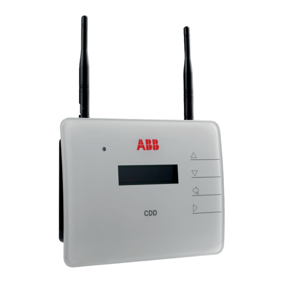
Plan the installation escription of the CDD The ABB MICRO Inverters associated with the CDD can be monitored using the CDD display, the CDD web server interface, or from the Aurora Vision monitoring portal. The CDD display allows simultaneous monitoring of all the associated inverters. The following information can be viewed by navigating in the display menu: •... -
Page 10: System Integration
These operations can be carried out using the CDD display or the Web Server integrated in the CDD. When configuring using the Web Server it is necessary to connect the CDD to a PC via Ethernet or Wireless (see configuration and connection details in part 4). -
Page 11: Select The Installation Location
Analyze the communication quality considering the possibility of having to extend the radio antenna externally (CDD Antenna Extension Cable). • Each CDD has a capacity to monitor up to 30 MICRO inverters; for more than 30 MICRO inverters, it is necessary to install more than one CDD. •... -
Page 12: Evaluate The Installation Position
The radio signal can be limited by obstacles and distance. In order to boost the signal strength, position the antenna of the CDD in a parallel line to the inverters. The antenna has a deadzone at the tip that should not be facing the inverters. - Page 13 Before permanently mounting the system it is important to consider the possible scenarios shown below and evaluate the right position for the CDD and MICRO inverters. The distances used in the examples are between the CDD and the closest MICRO inverter available. Evaluate the...
-
Page 14: Mount The Cdd
The depth of the holes must be around 30 mm. • Insert plugs in the holes and tighten the countersunk screws supplied. • Fasten the CDD by putting the head of the screws in the two holes on the back. - 14 -... -
Page 15: Onnect And Configure The Cdd
• Cabled - The CDD is equipped with an Ethernet port and can be directly connected to a PC or router. A direct connection to a computer should only be used during configuration of the system to access the local web server, not for regular monitoring. -
Page 16: Wireless Connection To The Internet
* Check compatibility list in the appendix and on the website; a standard access point may be utilized to bridge the CDD to an incompatible router. The process of detecting WiFi networks within range begins as soon as the green LED is diplayed on the CDD. •... -
Page 17: Secure Networks Without A Mac Address Filter
• Press ENTER to confirm the selection and ESC to return to the menu. If the last network that the CDD was configured for is not available, the CDD will not connect to any network. To configure the CDD for a new WLess network, disable the Autoconnection feature and reboot the CDD. -
Page 18: Dhcp Configuration
(or press any button from the GENERAL INFORMATION ..display). • Scroll to WebServer IP from the BASIC menu. The IP address that is displayed will be used in part 4, to access the CDD Web Server using a computer or tablet. - 18 -... -
Page 19: Ethernet Connection To The Internet
Once the wireless is disabled the CHANGE SETTINGS menu will be used to modify the Network settings. • Press and hold the UP and DOWN buttons on the CDD display at the same time until the Set Password screen is displayed. -
Page 20: Firmware Upgrade
(local web server) Ethernet cable If the computer is directly connected to the CDD without a router, and if the computer is set for an automatic IP address, it is necessary to change the Network settings on the computer fol- lowing the procedure below: •... -
Page 21: Dd Display Operations
The status of the inverter is indicated by the constant or intermittent lighting of the LED located on the front of the CDD above the two line display. The display also shows a message identifying the operation which is being carried out or the alarm/anomaly recorded. -
Page 22: Description Of The Display Menus
The CDD display consists of 2 lines with 16 characters per line. The operating status and statistical data of the inverter can be viewed along with service messages for the operator, warning and alarm messages. Inverter settings can also be modified using the display menus. - Page 23 Set Password screen is displayed on the CDD. • Use the UP and DOWN buttons on the CDD to enter the default password 0010, pressing ENTER after each entry. The three MAIN menus are used to:...
-
Page 24: General Information Cyclical Display
EXTRA: Y = number of inverters over limit of 30 Alarm status displays presence or absence of alarms, see section 7 for alarm codes Date and time set on the CDD, use CHANGE SETTINGS menu to modify values WLess strength of network connection, represented by 1 to 4... -
Page 25: Main Menu - View Information
CDD or MIC (inverter) serial number Change Settings modify CDD settings and acquire inverters Change Language > of the CDD, press ENTER and select language from the list Set Date/Time > of the CDD, press ENTER to change... - Page 26 4 - CDD display operations - 26 -...
-
Page 27: Cquire The Micro Inverters
Acquire the MICRO inverters cquisition process The acquisition of the MICRO Inverters by the CDD can be performed directly from the CDD display or with a PC or Tablet connected via a Wireless network or Ethernet cable using the CDD “web user interface”. -
Page 28: Acquire The Micro Inverters Using A Computer And The Integrated Web Server
MICRO inverters using a computer and the integrated web server On completing the connection and configuration phase in part 4, the CDD will be connected to a computer. A browser with active Javascript must be used to view the Local Web Portal pages properly. - Page 29 5 - Acquire the MICRO inverters Select MicroManager from the drop-down CONFIG menu on the Home page Authentication is required Enter the default access credentials Username: admin - Password: admin Press OK Click to view a drop down list of timezones Use the drop-down list to view grid/country standards Click confirm to...
- Page 30 5 - Acquire the MICRO inverters Click START ACQUISITION to begin scanning Inverters are identified by MAC address (MACRF) and/or serial number (SN) There is no timeout for the acquisition procedure. Click on STOP ACQUISITION to manually terminate the procdure once all the inverters are displayed.
- Page 31 Click here to complete the acquisition and register later • If the link to register the CDD has been selected (“CLICK HERE TO REGISTER..”), the registration welcome page will open. The registration procedure is described in part 6, System monitoring. •...
- Page 32 5 - Acquire the MICRO inverters - 32 -...
-
Page 33: Ystem Monitoring
To start the self-registration process go to https://register.auroravision.net/cdd?mac=AA: BB:CC:DD:EE:FF:GG:II (The page will automatically open at the end of the acquisistion process for the MICRO inverter when “CLICK HERE TO REGISTER YOUR CDD XX:XX:XX:XX:XX:XX:XX:XX”) is selected.) Read through the overview... - Page 34 Step 3 • Link and validate the CDD to the solar power site. • Make sure the CDD is connected to the internet. •...
-
Page 35: Aurora Vision Plant Viewer
In addition to monitoring, the portal offers automatic upgrade of the firmware installed in the MICRO inverters and the CDD. When new firmware is available, an e-mail is sent to the registered email address to alert the need for an upgrade. -
Page 36: Local Monitoring Using The Cdd Web Server
CDD web server In order to access the CDD local web server, a PC or tablet must be connected to the same local network, i.e. through the same Ethernet or Wireless router, or connected directly to the CDD using an Ethernet cable. Enter the IP address (page 24) and wait until the Home page is displayed. -
Page 37: View Menu
MICRO inverter * Each MICRO Inverter sends a package of data to the CDD once a minute. In order to accurately evaluate a CDD positioning, wait 15 minutes from the power-on of the device. -
Page 38: Config Menu
Config > Date/Time: used to adjust date and time. Config > CDD clone: allows configuration of a new CDD with the same settings as a previous CDD by using the last 4 pairs of digits of the old CDD’s MAC address. - Page 39 6 - System monitoring Config > CS param: modification of country standard Config > Ground/Fault/Energy: options to reset ground fault and/or reset energy history for statistical views Config > Change Pass: use to change the default password (admin) Enter default password enter and retype new password and click Confirm to change...
-
Page 40: Events Menu
6 - System monitoring VENTS menu A log of system events relating CDD and inverters is displayed in the Events menu. This includes errors (Exxx) and alarms (Wxxx)codes; see Appendix, Part 5, for a complete description of these events. PGRADE menu The Upgrade menu can be used to upgrade firmware of the CDD and MICRO inverter and load an updated country standard list. - Page 41 6 - System monitoring CDD Local Upgr.: The CDD firmware is available on the web site https://registration.ABBsolarinverters.com or by contacting customer service. Download the files and save them on a computer to perform a local updgrade. There will be two separate files for Ethernet and wireless firmwares.
-
Page 42: Registration Menu
6 - System monitoring uP MICROinv Fw: used to update the microproccesor firmware of the CDD. The firmware must first be downloaded and saved on a computer in order to browse and select the files for upload, see CDD Local upgrade above. -
Page 43: Ppendix
Appendix he MICRO inverter system This system is composed of a group of MICRO Inverters that convert direct electric current from a photovoltaic module into alternating electric current and feed it into the utility grid. Photovoltaic modules transform energy from the sun into direct current (DC) electrical energy (through a photovoltaic field, also called photovoltaic module). -
Page 44: Description Of The Cdd
CDD. larm messages and codes The MICRO Inverter is capable of communicating errors/warnings via radio to the associated CDD. The table below provides a description of the alarm messages and error codes displayed on the CDD. - Page 45 Verify the MICRO inverter tempera- tion conditions ture readings (see the Internal Web b) Internal inverter fault Server section in the CDD manual). If one of the temperatures remains at a value which is not compatible with the environmental conditions (e.g. -40°C internal temp.
- Page 46 Internal Error caused by the initialization of grid, and no actions are required to communication between the CDD solve the problem. and the MICRO inverters. b) If the error systematically persists, b) Systematic occurrence of this...
- Page 47 Firmware updates Comp condition may be generated if a are performed via the Internal Web MICRO inverter is replaced. Server (see the CDD manual), with the software package obtained from cus- tomer service. E052 The alarm is generated when the...
- Page 48 7 - Appendix Display code Cause Solution LED status Message W003 This alarm is generated when If the error is generated only on one of Blinking one or more grid parameters lie the installation MICRO inverters, this green outside the permitted range set may be due to an inverter fault.
-
Page 49: Making A Service Call
Error message or code outine maintenance The CDD has no user-serviceable part and needs no maintenance interventions. Do not attempt to dismantle the equipment or make any internal repairs!. Any attempt to open the equipment could comprise the integrity of the casing’s insulation and violate the integrity of the NEMA 1 rating and/or create a hazard. -
Page 50: Wireless Routers Compatible With Cdd
7 - Appendix ireless routers compatible with CDD Below is the list of wireless routers tested for compatibility with CDD firmware 2.1.3 or later. The CDD device is associated with the MICRO-0.25-0.3-0.3HV-I-OUTD-US-208/240.. Vendor Model FW Version 2Wire 2701HG-B 5.29.109.11 ActionTec GT704-WG 3.20.3.3.5.0.9.2.10... - Page 51 7 - Appendix Vendor Model FW Version NetGear WG103 WG103_V2.0.25 NetGear WGR614v9 V1.0.9_1.0.1NA NetGear WGT624 NetGear WGT624v2 V2.0.16_1.0.1NA NetGear WN2000RPT V1.0.0.2NA NetGear WN802T v2 WN802Tv2_2.0.2 NetGear WNDR3300 V1.0.14_1.0.14NA NetGear WNDR3700 V1.0.0.6 NetGear WNR1000v2 V1.0.0.5NA NetGear WNR1000v3 V1.0.2.18_2.1.5.1 NetGear WNR200v3 V1.0.1.26 NetGear WNR854T 1.4.34NA...
- Page 52 For more information on ABB products and services for solar applications, navigate to www.abb.com/solarinverters...
- Page 53 www.abb.com/solarinverters...
Need help?
Do you have a question about the CDD and is the answer not in the manual?
Questions and answers