Table of Contents
Advertisement
Advertisement
Table of Contents
Troubleshooting

Related Manuals for ABB VSN700


Summary of Contents for ABB VSN700
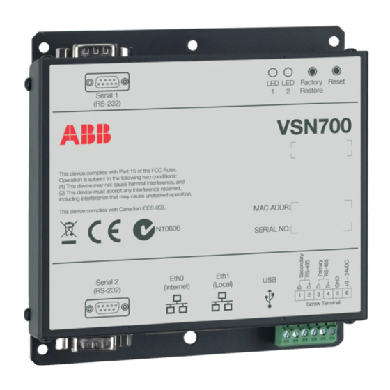
- Page 1 ABB solar monitoring Product manual VSN700 Data Logger...
-
Page 2: Important Safety Instructions
VSN700 Data Logger Product Manual Operators are required to read this manual and scrupulously follow the indications reported in it, since ABB cannot be held responsible for damages caused to people and/or things, or the equipment, if the warranty conditions are not observed. - Page 3 VSN700 Data Logger Product Manual Not included in the supply ABB accepts no liability for failure to comply with the instructions for correct installation and will not be held responsible for systems upstream or downstream the equipment it has supplied. It is absolutely forbidden to modify the equipment.
-
Page 4: Table Of Contents
Plant Viewer access for end users ....................15 Adding an ABB weather station .................... 18 Configuration for a weather station device ..................19 Interfacing VSN700-05 with SCADA systems ............... 21 Power-One SunSpec Adapter ......................21 Modbus TCP server ..........................21 Data logger configuration for SCADA or other monitoring systems .......... -
Page 5: System Overview
Internet connected device. The installer logs on to the Aurora Vision website to register the VSN700 series data logger and ensures that the logger is correctly passing information to the servers. The installer provides a URL to the end user for access to Aurora Vision Plant Viewer. -
Page 6: Vsn700 Data Logger Models
VSN700 Data Logger Product Manual Commercial and Utility Application with VSN700-05 The information in this document applies to all VSN700 Data Logger models. This guide provides instructions for installing the data logger hardware to work directly with ABB (or legacy Power-One) solar inverters and for setting up the Aurora Vision management system for remote data access. -
Page 7: Installation
Installation Qualified personnel with appropriate training and experience must perform installation of the VSN700. Follow standard safety precautions during all procedures. Appropriate personal protection equipment (PPE), such as safety gloves and safety glasses is recommended. During normal operation, dangerous voltages flow through many parts of the system, including: terminals, all I/O Modules (Inputs and Outputs) and their circuits. -
Page 8: Vsn700 Installation
3. Mount the data logger. The logger comes with flanges with pre-drilled holes for easy mounting. A DIN rail mounting kit comes with the VSN700-05-00 model and can be optionally ordered with other models. All data logger versions require a weather protected site. - Page 9 6. Connect the other end of the shielded twisted-pair wire to Secondary RS-485 terminals on the data logger. Use the table below and the figure on page the next page to make the proper connections. See the section on Adding an ABB Weather Station for information on connections for an attached weather station.
- Page 10 See the figure below. VSN700-05-00 models come with a DIN Rail kit for mounting directly on a DIN rail within an inverter. After DIN Rail mounting, connect the data logger directly to a 9V-24V (±10%) DC voltage source capable of supplying greater than 7.2VA.
-
Page 11: Inverter Address Configuration
Residential or Commercial model VSN700, they must be attached to the Secondary RS-485 port on the data logger. ABB inverters (PVS, PRO, TRIO) may only use, or are configured to use, Modbus RTU protocol and must be attached to the Primary RS-485 port on Commercial data loggers. -
Page 12: Commissioning
Ensure that the wireless connection is operational with a laptop before connecting it to the Eth0 port of the data logger. ABB does not provide Internet service or the cables required to connect the data logger to the Internet. -
Page 13: Configure The Data Logger
VSN700 Data Logger Product Manual Configure the data logger The installer must use a laptop with an Ethernet cable to communicate directly to the data logger’s web-based user interface for configuration. The data logger’s web server has many options and capabilities, but here we only describe those necessary to get your system up and running. -
Page 14: Configure For Devices
Secondary RS-485 port. Optional weather stations used with the Commercial version VSN700 are connected to the Primary RS-485 port. See Section 4 if you are adding a weather station. See Section 5 for configuration options if you are using a Max version VSN700. -
Page 15: Asset Registration
VSN700 Data Logger Product Manual 2. The data logger acts as a router. From your laptop connected to Eth1, verify internet connectivity by opening up an Internet browser window and connecting to www.auroravision.net. 3. The remaining steps for commissioning are performed via the Internet to check end-to-end communications. - Page 16 VSN700 Data Logger Product Manual 2. Select the Plant from the asset list in the screen area to the left. 3. Once the correct Plant is displayed, select Share from the Actions menu. - 16 -...
- Page 17 VSN700 Data Logger Product Manual 4. A page is displayed to configure the user’s Plant Viewer options. Scroll down to the Published View section. The URL to provide to the customer is in the Share URL field. For detailed information about plant sharing options see the Plant Portfolio Manager User Guide.
-
Page 18: Adding An Abb Weather Station
VSN700. Weather stations are not supported by the Residential version VSN700. Weather stations can be attached to any port configured for Modbus RTU on the Max version VSN700. 1. Connect shielded twisted-pair wire to the RS-485 terminals on the weather/environmental station. -
Page 19: Configuration For A Weather Station Device
VSN700 Data Logger Product Manual for the minimum required voltage and maximum allowed wire gauge. If unable to meet these specs because of voltage drop then a separate power supply closer to the weather station must be used. DO NOT USE CAT5/6 CABLE FOR THE POWER WIRES. - Page 20 VSN700 Data Logger Product Manual The port configuration for the Primary RS-485 port on the VSN700 Commercial must remain set to Modbus RTU (default value). Configuration of the Primary RS-485 port only needs to be completed when using an optional weather station.
-
Page 21: Interfacing Vsn700-05 With Scada Systems
VSN700 Data Logger Product Manual Interfacing VSN700-05 with SCADA systems This section describes how to interface external monitoring or SCADA systems with the VSN700- 05 data logger and is intended only for these Max version data loggers. This section does not apply to the Residential and Commercial versions. -
Page 22: Data Logger Configuration For Scada Or Other Monitoring Systems
VSN700 Data Logger Product Manual Data logger configuration for SCADA or other monitoring systems Set a Static IP Address for the data logger Connect a PC to the Eth1 port and browse to address to access the data http://172.17.17.1 logger’s web based configuration UI. In the Network tab configure a static IP address for the data logger’s Eth0 port that is either within the same subnet as the SCADA system or can be routed... -
Page 23: Communication With Devices By Scada Or Monitoring System
VSN700 Data Logger Product Manual Configure Global Settings menu. The following image shows an example where one interface is configured for Modbus RTU and the other interface for Power-One SunSpec Adapter. Save the changes by pressing the blue floppy disk icon. -
Page 24: Adding 3Rd Party Devices
VSN700 Data Logger Product Manual <Eth0_IP_address>:502:14. To communicate with a Modbus RTU device at Modbus slave ID (address) 26 connected to the Secondary RS-485 port which has been configured for Modbus RTU, the Modbus TCP command would be pointed to: <Eth0_IP_address>:503:26. -
Page 25: Modbus Tcp Client
VSN700 Data Logger Product Manual 8. Press the Apply icon at the top to commit the changes. 9. After making changes, you are returned to the Devices page with the status indicators, as shown below. Modbus TCP client In addition to acting as a Modbus TCP server, the data logger can act as a Modbus TCP client and be set up to poll data from supported Modbus TCP based devices through the Eth0 and/or Eth1 interfaces. -
Page 26: Troubleshooting
4. If all of the previous steps are correct restart the data logger by unplugging and then supplying power to the data logger. 5. If all of the previous steps do not help this issue, contact ABB Technical Support. Issue: I cannot connect directly to the web interface on the data logger. -
Page 27: Troubleshooting/Resetting A Data Logger
DC you have a short in the data wires. If the difference between the two measurements is greater than 3V DC then you may have an open circuit. 5. If all of the previous steps do not help this issue, contact ABB Technical Support. Troubleshooting/Resetting a data logger Consult this section if you suspect there is a problem with the data logger. -
Page 28: How To Contact Abb Technical Support
If you require an advance replacement to be shipped before the RMA unit has been received by ABB, you will need to submit a valid purchase order for the replacement unit, referencing the RMA number on the P.O. When we receive the faulty unit, we will credit the cost of the replacement, if it is covered by the warranty. -
Page 29: Data Logger Specifications
VSN700 Residential: Up to 5 ABB (or legacy Power-One) single-phase or small three-phase • (Trio 5.8/7.5/8.5) string inverters. VSN700 Commercial: Up to 10 ABB (or legacy Power-One) string inverters and one ABB • weather station. String inverters can be single-phase or three-phase. - Page 30 The logger uses this port for network time services (NTP). (preferred) Network Hosts The logger will connect to the following hosts. Some servers owned by ABB, and others are customer or ISP servers. Servers listed as owned by “Customer IT/ISP” must be configured in the logger using either DHCP or as static network information.
- Page 31 VSN700 Data Logger Product Manual Logger Network Configuration The logger requires a valid network configuration in order to operate. This information can either be provided by a DHCP server provided by the customers network (the default), or the logger can be configured with static network information.
- Page 32 VSN700 Data Logger Product Manual Contact us www.abb.com/solar YOUR ABB DISTRIBUTOR SOLIGENT 800-967-6917 www.soligent.net...
Need help?
Do you have a question about the VSN700 and is the answer not in the manual?
Questions and answers