
Related Manuals for ABB PQFM


Summary of Contents for ABB PQFM
- Page 1 — INST RUCTION MANUAL Power Quality Filter PQFM Installation, operation and maintenance instructions...
-
Page 2: Table Of Contents
6.7.3 Contactor type for different unit ratings ..................53 6.7.4 Optional surge arrester circuit (CE version only) ................ 53 6.8 Connection of the PQFM to the network ....................54 6.9 Selection of the current transformers ......................56 6.10 Current transformer installation ........................59 6.10.1 Basic rules for correct CT installation ..................... - Page 3 6.10.9 CT connections for the case that passive filters and active filters are installed in the same network ..............................68 6.11 Electrical interconnection of PQFM cubicles and IP00 plates ............69 6.11.1 Mechanical interconnection ....................... 70 6.11.2 Control board cable interconnection ....................71 6.11.3 Earth points interconnection ......................
- Page 4 8.6.2.4 Checking the correct connection of the CTs with a Fluke 41B ....... 172 8.7 Step 6: Before starting the filter......................... 172 8.8 Step 7: Start the filter ............................. 172 8.9 Step 8: Generate filter load .......................... 173 4 Table of contents ç Manual Power Quality Filter PQFM...
- Page 5 11.4.1 Verification of the PQF-Manager status and the system LEDs ..........209 11.4.2 Fault tracing ............................210 12 Technical specifications ......................... 223 12.1 What this chapter contains .......................... 223 12.2 Technical specifications ..........................223 Manual Power Quality Filter PQFM ç Table of contents 5...
-
Page 6: Introduction To This Manual
9) and Maintenance instructions (Cf. Chapter 10) of this manual. Compatibility The manual is compatible with all filters of the 3-wire PQFM-range with PQF-Manager software versions or higher. V1 : V26 r3001 V3 : V2 r0 V2 : V11 r23 V4 : V0.1 r8... -
Page 7: Related Publications
Power Quality Filter, Active Filtering Guide [English] PQ-Link Installation and user’s guide [English] PQF Modbus CD [English] ABB PQF Active Filters - Raising system reliability to unprecedented levels [English] ABB quick start Manual Power Quality Filter PQFM ç Introduction 7... -
Page 8: Safety Instructions
PQFM should be carried out by qualified electricians. Do not attempt to work on a powered PQFM. After switching off the supply to the PQFM, always wait at least 25 minutes before working on the unit in order to allow the discharge of DC capacitors through the discharge resistors. -
Page 9: Upon Reception
PQFM active filter. Delivery inspection Each PQFM is delivered in an enclosure designed to protect adequately the equipment during shipment. Upon reception of the equipment, make sure that the packing is in good condition. Verify the state of the shock and tilting indicators (if mounted on the enclosure). - Page 10 Table 1: Maximum allowed ambient conditions during transportation Transportation (in the protected package) Temperature -25 to 70°C (-13 to 158°F) Relative humidity Max. 95% Chemical class 3C3 Contamination levels (IEC 60721-3-3) Mechanical class 3S3 10 Upon Reception ç Manual Power Quality Filter PQFM...
-
Page 11: Identification Tag
ABB factory in Belgium). Packing for a longer storage period can be done on request. If your PQFM is not installed once unpacked, it should be stored in a clean indoor, dry, dust free and non-corrosive environment. The storage temperature must be between - 25°C (-13°F) and 70°C (158°F) with a maximum relative humidity of 95%, non-condensing. -
Page 12: Hardware Description
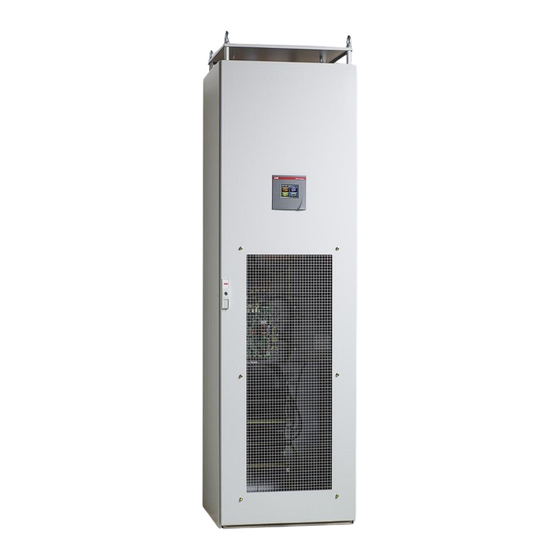
— 4 Hardware description What this chapter contains This chapter describes a typical PQFM-filter system and discusses its main components. Typical PQFM filter panel layout The PQFM active filter is basically composed of two parts (Figure A filter controller that determines the anti-harmonic current to be injected based on the line current measurements and the user’s requirements. - Page 13 For more information on cabling the user connections, please refer Chapter Figure 4 shows a typical PQFM master filter panel in CE version. Figure 5 shows a typical PQFM master filter panel in cULus version. Manual Power Quality Filter PQFM ç Hardware description 13...
- Page 14 Figure 4: Example of a typical PQFM master filter panel (CE version) 14 Hardware description ç Manual Power Quality Filter PQFM...
- Page 15 Figure 5: Example of a typical PQFM master filter panel (cULus version) The input/output connections and protection description is given in Table Table 4: Input/Output connections Item Input/output connections CT connection terminals Main power connection Auxiliary fuse protection Filter panel main fuse protection (option for CE version) PQF-Manager user interface with connection terminals for user I/O (e.g.
-
Page 16: The Pqf Current Generator Hardware
The current generator is physically organized in power units. Each filter cubicle contains one power unit. A PQFM filter can contain up to 8 power units. Power units can be combined in a master-slave arrangement or in a master-master arrangement, the latter giving full operational redundancy. -
Page 17: The Pqf Main Controller
Interface to the IGBT-inverters. Measurement of system voltages and currents for control, protection and presentation purposes. Figure 7 depicts the controller interface diagram of the PQFM active filter. Manual Power Quality Filter PQFM ç Hardware description 17... -
Page 18: The Pqf-Manager User Interface
All slave units have their own AC-connection and main contactor protection. A PQFM active filter system consists of up to 8 units. Additional units to the first master unit may be master or slave units. Slave units do not have a PQF-Manager. - Page 19 When the PQF-Manager closes one of its output relays, the corresponding symbol lights up. The digital outputs of the PQF-Manager are discussed later in this section. Filter selection Start stop acknowledgment fault Manual Power Quality Filter PQFM ç Hardware description 19...
- Page 20 The terminal explanation is given next: Digital input 1 and 2 The digital inputs can be used for three different functions: Implementation of remote control functionality; Implementation of local on/off buttons (not provided); 20 Hardware description ç Manual Power Quality Filter PQFM...
- Page 21 Filter starts on rising edge PQF-Manager setup for digital input: Edge (a) (b) Local ON/OFF buttons No effect Filter stops on rising edge PQF-Manager setup for digital input: Edge (a) (b) Manual Power Quality Filter PQFM ç Hardware description 21...
- Page 22 PQF-Manager. Table gives an overview of the possible PQF-Manager settings for a digital output and the effect on the corresponding digital output relay. 22 Hardware description ç Manual Power Quality Filter PQFM...
- Page 23 For full redundant functionality, it is recommended to monitor the digital outputs of all the units in the filter system. The default set-up for the digital contacts is given in Table Manual Power Quality Filter PQFM ç Hardware description 23...
- Page 24 Modbus RTU adapter interface (optional) connection The Modbus adapter interface is connected at this location. The output of the interface is an RS-485 socket. The interface is described in the Modbus RTU interface manual. 24 Hardware description ç Manual Power Quality Filter PQFM...
-
Page 25: Location Of The Main Pqfm Components
4.6 Location of the main PQFM components 4.6.1 Active filter components Figure 10 shows a picture of the PQFM in CE version. Figure 11 shows a picture of the PQFM in cULus version. Manual Power Quality Filter PQFM ç Hardware description 25... - Page 26 Figure 10: Example of typical PQFM master main components (CE version) 26 Hardware description ç Manual Power Quality Filter PQFM...
- Page 27 Circuit diagram designation Main contactor (MC) Fuse holder auxiliaries circuit Auxiliary voltage transformer DC voltage power supply 24V CT connection terminal Preload circuit resistors R7/R6 Preload circuit diode V1/V2 Main earth connection point Manual Power Quality Filter PQFM ç Hardware description 27...
- Page 28 CAN bus connectors for use in a multi-module filter arrangements. The main controller board is shown in Figure Figure 12: PQF main controller board The designation of the principal terminals is given in Table 28 Hardware description ç Manual Power Quality Filter PQFM...
- Page 29 LED 4: ON, OFF or blinking irregularly: DSP processor not running properly PQ-Link communication opto-isolated serial link connector Filter unit address selector (3 bottom DIP switches with ABB logo at bottom left) and CAN bus termination (top DIP switch): Symbols used: R: right – L: left...
-
Page 30: Active Filter Door Components And Protective Grid
Active filter door components and protective grid The active filter master panel door contains the PQF-Manager and a protective grid connected to the filter frame. At the bottom of the protective grid a cooling fan is mounted. 30 Hardware description ç Manual Power Quality Filter PQFM... -
Page 31: Mechanical Design And Installation
In case you have a problem, please notify it to our service support mail box: jumet.services@be.abb.com. Installation location requirements The PQFM is suitable for indoor installation, on firm foundations, in a well-ventilated area without dust and excessive aggressive gases where the ambient operating conditions do not exceed the following values:... -
Page 32: Airflow And Cooling Requirements
Airflow and cooling requirements The PQFM dissipates an amount of heat that has to be evacuated out of the room where the filter is located. Otherwise, excessive temperature rise may be experienced. Please note that life of the electrical equipment decreases drastically if the operating temperature exceeds the allowable limit (divided by 2 every 10°C/23°F). -
Page 33: Standard Cubicle Dimensions, Fixing Holes And Clearances
Standard cubicle dimensions, fixing holes and clearances Standard PQFM cubicles are of the Rittal TS8 type and have dimensions of 600 x 600 x 2150 mm (Width x Depth x Height). The cubicles have an elevated roof with lifting lugs. - Page 34 PQFM from the top or the bottom. Note that if the “top cable entry option” has not been installed, the customer has to make a cable pass through in the filter roof and protecting grid. In order to do this, remove the roof by unscrewing the lifting lugs.
-
Page 35: Instructions For Mounting Ip00 And The Pqf-Manager In Cubicles
PQFM 1 unit PQFM 2 units PQFM 3 units Figure 15: Standard dimensions for PQFM filters with up to 3 power units (base frame for multi- unit filters is optional) 5.5 Instructions for mounting IP00 and the PQF-Manager in cubicles PQFM filters can be obtained in plate execution (IP00-version). - Page 36 Figure 16: IP00 plate with indication of its physical size and its fixation holes The plate has to be fixed into the customer’s cubicle. The cubicle has to be in accordance with ABB’s requirements for cooling and airflow and must have the mechanical strength to support the PQF plate.
- Page 37 (example for Rittal cubicles). Figure 18: Bottom fixation of IP00 plate in a cubicle Figure 19 shows how a top fixation can be realized (example for Rittal cubicles). Manual Power Quality Filter PQFM ç Mechanical design and installation 37...
- Page 38 Next to mounting the plate into the cubicle, the PQF Manager user interface has to be mounted on to the door. This can be done by following the guidelines presented next (Figure 21). 38 Mechanical design and installation ç Manual Power Quality Filter PQFM...
-
Page 39: Mechanical Interconnection Of Pqfm Cubicles
Mechanical interconnection of PQFM cubicles This section explains how to mechanically interconnect PQFM units (master-master, master-slave or slave-slave). Figure 22 outlines the steps to undertake to mechanically interconnect two PQFM units. Manual Power Quality Filter PQFM ç Mechanical design and installation 39... -
Page 40: Mechanical Preparation Of A Common Cable Entry Cubicle
This cubicle contains a bus bar system to which the supply cables have to be connected and which distributes the power to the power units 40 Mechanical design and installation ç Manual Power Quality Filter PQFM... - Page 41 Figure 23 shows an example of a common cable entry cubicle.. Figure 23: Example of a common cable entry cubicle for a PQFM As can be seen in Figure 23 the cubicle has an elevated roof fixed by the lifting lugs and underneath it has a protecting grid.
-
Page 42: Electrical Design And Installation
It also gives electrical connection examples for popular filter options. WARNING: The PQFM is able to operate on networks where the supply voltage is up to 10% higher than the equipment’s rated voltage (inclusive of harmonics but not transients). -
Page 43: Instructions For Connecting The Pqf-Manager To An Ip00 Filter System
The CE version of active filter complies in its standard version with the following EMC guidelines: EN/IEC 61000-6-2: Immunity standard for industrial environments, Industrial level. EN/IEC 61000-6-4: Emission standard for industrial environments, Class A. Manual Power Quality Filter PQFM ç Electrical design and installation 43... - Page 44 They are therefore a very significant source of EMC emission. Due to that, strong recommendations apply to the cable type and way of handling the connections of the earth terminal in a drive application. 44 Electrical design and installation ç Manual Power Quality Filter PQFM...
-
Page 45: Earthing Guidelines
6.6). No special EMC measures are needed. Standard cables types are well suitable for connecting the active filter to the supply. Earthing guidelines Each PQFM-cubicle two marked earth points (PE). The main earth point is situated at the top right side of the filter plate (Figure 25... - Page 46 (PE) and not to the N-conductor. Further, the following rules should be respected: When the PQFM consists of only one cubicle, the cubicle’s main PE-point must be connected directly to the installation’s PE-point. When the PQFM consists of more than one cubicle, all cubicles’ main PE-points must be connected directly to the installation’s PE-point and additionally, all...
-
Page 47: Selection Of The Power Cable Size
(Cf Section 6.4). NOTE: For cULus versions of PQFM, the maximum size of cables that can be connected to the fuse base is 350 kcmil The following steps have to be followed to determine the section of the power cables feeding the filter: 1. - Page 48 Remark: The cable sizing process discussed in point 2 above only takes into account the skin effect. Any further derating due to local standards and/or installation conditions (e.g. distance between cables, number of cables connected in parallel …) 48 Electrical design and installation ç Manual Power Quality Filter PQFM...
- Page 49 0.843 600MCM 0.997 0.999 0.993 0.997 0.987 0.994 0.975 0.989 1-1/0 0.955 0.98 0.93 0.965 0.904 0.95 0.877 0.93 300MCM 0.844 0.908 350MCM 0.804 0.876 500MCM 0.768 0.843 600MCM Manual Power Quality Filter PQFM ç Electrical design and installation 49...
-
Page 50: Selection Of The Power Cable Protection/Filter Input Protection Scheme
CE version protection scheme Standard CE versions of active filter do not have an incorporated power circuit protection. This one can optionally be obtained. Alternatively, the customer can install 50 Electrical design and installation ç Manual Power Quality Filter PQFM... - Page 51 Voltage rating and short circuit current handling capability should be in accordance with the network characteristics. As an alternative to fuse protection, MCCB protection of appropriate sizing can also be used. When the customer protection is in place, the following PQFM input protection will result. Customer added protection...
-
Page 52: Culus Version Protection Scheme
Table 21: Optional power circuit fuse characteristics for PQFM filters (CE version) Filter rating [A] Rated Voltage (Vrms) Power circuit fuse Irms fuse fuse type (Arms) (kA) at rated voltage 70 – 100 NH Fuse gL or gG 130 – 150... -
Page 53: Contactor Type For Different Unit Ratings
Remark: fuse short circuit current capability 6.7.3 Contactor type for different unit ratings All PQFM units incorporate a main contactor. Depending on the filter rating, a different contactor type may be used. Table 25 details the contactor type. Table 25: Contactor type for different unit ratings... -
Page 54: Connection Of The Pqfm To The Network
Local regulations and requirements prevail in determining how the equipment has to be connected to the network. In accordance with good cabling practices, ABB strongly suggests that the feeding cables to the filter are protected by their own cable protection device. - Page 55 Figure 31: Filter connection main terminals (CE version) Figure 32: Filter connection main terminals (cULus version) Note for common cable entry PQFM: if the filter is fitted with an additional cubicle for common cable entry, the feeding power cables have to be connected to the busbar installed in the connection cubicle.
-
Page 56: Selection Of The Current Transformers
Each filter unit in a filter system has to monitor the line current in order to determine the harmonic load and function correctly. This is done by three current transformers (CTs). For proper operation of the PQFM standard accuracy CTs with the following minimum specifications have to be used: 5 A secondary current rating. - Page 57 CTs have to be used. All summing CTs must have the same ratio. More information on how to install the summing CTs is given in next section. Manual Power Quality Filter PQFM ç Electrical design and installation 57...
- Page 58 Figure 35: Flow chart for CT determination 58 Electrical design and installation ç Manual Power Quality Filter PQFM...
-
Page 59: Current Transformer Installation
This must be done through a daisy chain connection with return path configuration. By default, the PQFM active filter is provided with CT terminals that are not shorted. A set of shorting plugs is provided with the filter. They should always be kept with the filter and be accessible for service engineers. - Page 60 CT connection terminal X21 (1 = at top, 6 = at bottom) Figure 37: Location of the CT connection terminal X21 in the PQFM The terminal block X21 can handle control cable wiring with sections from 2.5 mm² to 10 mm².
- Page 61 Case 7: CT connections for the case that detuned capacitor banks are installed adjacent but downstream to the active filter CTs Case 8: CT connections for the case that passive filters and active filters are installed in the same network Manual Power Quality Filter PQFM ç Electrical design and installation 61...
-
Page 62: Ct Locations For The Case Of Global Compensation - One Feeding Transformer
Figure 40: CT connections for the case of individual compensation – one feeding transformer The connection method for the three CTs to the active filter is described in Section 6.10.1. 62 Electrical design and installation ç Manual Power Quality Filter PQFM... - Page 63 CT whose secondary is 5A (5+5/5A). The summation CT is then connected to the active filter in accordance with Section 6.10.1. A total of 3 summation CTs (one per phase) must be used. Manual Power Quality Filter PQFM ç Electrical design and installation 63...
-
Page 64: Ct Locations For The Case Of Two Independent Feeding Transformers
Figure 44: Case of two independent feeding transformers By connecting the CTs as described in Figure 45 it is possible to filter the harmonics and to correct the power factor under the aforementioned conditions. 64 Electrical design and installation ç Manual Power Quality Filter PQFM... - Page 65 If only T2 feeds the load, I1 will be zero. Please note that the above described connection must be done for each phase. The CT ratio to be programmed in the filter is: 2×X/5. Manual Power Quality Filter PQFM ç Electrical design and installation 65...
-
Page 66: Ct Locations For The Case Of Feeding Transformer And Backup Generator
P2, L S1, k P1, K S2, l P2, L Figure 47: CT connections for the case of a feeding transformer with backup generator (to be done for each phase) 66 Electrical design and installation ç Manual Power Quality Filter PQFM... -
Page 67: Ct Connections For The Case That Plain Capacitors Are Present In The Network
For these reasons ABB suggests to replace the plain capacitor by a detuned capacitor bank when harmonics are present in the network. -
Page 68: Ct Connections For The Case That Detuned Capacitor Banks Are Installed Adjacent But
Figure Feeding transformer Filter CTs PQFx Linear and non-linear loads Passive filter Figure 51: Recommended connection diagram for PQFM and passive filters 68 Electrical design and installation ç Manual Power Quality Filter PQFM... -
Page 69: Electrical Interconnection Of Pqfm Cubicles And Ip00 Plates
SDP function may stop filtering the affected harmonics temporarily resulting in a reduced overall filtering performance. 6.11 Electrical interconnection of PQFM cubicles and IP00 plates This section explains how to electrically interconnect different PQFM cubicles and IP00 plates. Figure 54 shows schematically which interconnections have to be made between two filter cubicles or IP00 plates. -
Page 70: Mechanical Interconnection
CT interconnection cable (not provided) Earth interconnection (not provided) Five steps have to be followed to electrically interconnect a new PQFM cubicle/plate with an existing filter/plate. They are outlined in the next five paragraphs. 6.11.1 Mechanical interconnection Ensure that the new cubicle is mechanically interconnected with the existing filter. For guidelines on how to mechanically interconnect add-on filter cubicles, please refer to Section 5.6. -
Page 71: Control Board Cable Interconnection
Interconnect the earth points of the different units (Cf. Figure 53 item 3) and earth the new unit individually. Refer to Section 6.5 for more information on this topic. Manual Power Quality Filter PQFM ç Electrical design and installation 71... -
Page 72: Ct Cable Interconnection
When the filter does not have an optional common cable entry cubicle, the same connection approach as used for the other filter units must be adopted. More information on how to connect a PQFM cubicle to the power supply can be found in Section 6.8. -
Page 73: Electrical Connections To The Pqf-Manager User Interface
The PQF-Manager is the user interface between the outside world and the filter controller. Depending on the user requirements, less or more electrical connections have to be made to it. Figure 57 shows the rear side layout of the PQF-Manager. Manual Power Quality Filter PQFM ç Electrical design and installation 73... - Page 74 The remainder of this section gives examples of how to cable different functions, i.e. Case 1: Cabling of remote control functionality. Case 2: Cabling of alarm functionality. Case 3: Cabling of warning functionality. 74 Electrical design and installation ç Manual Power Quality Filter PQFM...
-
Page 75: Cabling Of Remote Control Functionality
The power to the filter may then be restored. 6.12.1 Cabling of remote control functionality The PQFM has the possibility to be controlled by remote control. An example of this approach is a drive that is switched on at a location and which automatically gives a start command to the filter. - Page 76 PQF-Manager to the digital input setup menu and setting the digital input considered to ‘Disabled’. The remote control functionality can also be implemented on the Digital Input 2. 76 Electrical design and installation ç Manual Power Quality Filter PQFM...
-
Page 77: Cabling Of Alarm Functionality
Filter state Normally closed alarm contact state Normally open alarm contact state Open Closed Disconnected from the supply Closed Open Filter (auxiliaries) connected to the supply, no error present Manual Power Quality Filter PQFM ç Electrical design and installation 77... - Page 78 Figure 61: Cabling of the alarm status of a multi-unit filter consisting of masters only, using the NC alarm contact on each filter. In the Figure 61, the alarm bulb will be activated when both master units are in alarm. 78 Electrical design and installation ç Manual Power Quality Filter PQFM...
- Page 79 Figure 63: Cabling of the alarm status of a multi-unit filter consisting of masters only, using the NO alarm contact on each filter. In the Figure 63 above, the external input will be low if: Both master units are in alarm OR Manual Power Quality Filter PQFM ç Electrical design and installation 79...
-
Page 80: Digital Outputs
Note however that by default the digital outputs have been set up for monitoring other functions than alarms (cf. Table 10) Refer to Section 7.9.1.4 for guidelines on how to navigate to the digital output setup menu. 80 Electrical design and installation ç Manual Power Quality Filter PQFM... - Page 81 1 and 2 of the right hand terminal of the PQF-Manager (rear view, counting from top to bottom). This is clearly indicated in Figure 57 above. Manual Power Quality Filter PQFM ç Electrical design and installation 81...
-
Page 82: Cabling Of Warning Functionality
Otherwise, contact remains open. Table 32 gives a list of the warning conditions that can be assigned to a digital output. 82 Electrical design and installation ç Manual Power Quality Filter PQFM... -
Page 83: Cabling Of The Digital Output Contacts To Monitor Other Filter Operation Modes Than Warnings And Alarms
With the PQF-Manager a set up can be made to either use always the main or the auxiliary settings. In addition, the possibility exists to switch between main and auxiliary settings ‘automatically’ according to a signal applied to a digital input of the PQF-Manager (Cf. Manual Power Quality Filter PQFM ç Electrical design and installation 83... - Page 84 Auxiliary settings are Activ. Main Main settings are used used Activ. Aux. Main settings are used Auxiliary settings are used Remark: Vlow = 0 Vdc, Vhigh = 15-24 Vdc 84 Electrical design and installation ç Manual Power Quality Filter PQFM...
-
Page 85: Implementation Of Local Start/Stop Buttons
WARNING: If a function is assigned to a digital input, the same function must never be assigned to the other digital input. Otherwise the filter may behave erratically. The PQFM active filter is equipped with a start/stop function integrated in the PQF- Manager user interface. If the customer desires this however, he can add extra start/stop buttons (not provided) to the filter system. - Page 86 The electrical requirements of the digital inputs are as discussed in Section 4.5. Figure shows a cabling diagram for implementing a start function and a stop function on the first digital input. 86 Electrical design and installation ç Manual Power Quality Filter PQFM...
-
Page 87: Electrical Connections Of Filter Options And Accessories
The connection of the Ethernet cable used for Modbus TCP communication (optional) The connection of the RS485 Modbus RTU adapter (optional) The connections of the aforementioned accessories are discussed next. Manual Power Quality Filter PQFM ç Electrical design and installation 87... -
Page 88: External Communication With Pqf
Modbus RTU protocol is implemented or any other standard software (OPC server, SCADA …). Figure 68: Location at rear of PQF-Manager where the serial communication cable has to be inserted 88 Electrical design and installation ç Manual Power Quality Filter PQFM... -
Page 89: Connection Of The Modbus Adapter
Modbus RTU, Modbus TCP and PQ-Link protocols. 6.13.2 Connection of the Modbus adapter For the connection setup of the Modbus adapter, please refer to the document “2GCS212013A0050-RS-485 Installation and Start-up guide”. Manual Power Quality Filter PQFM ç Electrical design and installation 89... -
Page 90: The Pqf-Manager User Interface
— 7 The PQF-Manager user interface What this chapter contains This chapter presents the features and operating instructions for the PQF-Manager user interface (Figure 69). Use the contents of this chapter as background information for the next chapters, which explain how to commission, operate and troubleshoot the active filter and how to set up various communication interfaces based on RS485 or Ethernet. -
Page 91: Pqf-Manager Overview And Navigation
Figure 70 Main screen of the PQF-Manager PQF-Manager overview and navigation All user inter-action with the filter is channeled through the PQF-Manager. It provides for the following main functions (Cf. Figure 69): Filter starting, filter stopping and acknowledgement of faults Selection of power module for which the relevant data is displayed Measuring, analyzing, logging Setting up the filter... - Page 92 The module status indicator: there are 8 numbered icons present on the left bottom of the screen, each representing a power module. The active modules are displayed in blue color; the faulty ones in red and those modules which are not present are greyed. Table 37 Module status icons Icons Status...
- Page 93 activate any digital output relay 1-6 if selected activate global alarm NO/NC relay Tprobe alarm 1 to 8 can activate global alarm NO/NC relay. Warnings Programmed warning can activate any digital output relay 1-6 if selected. Tprobe warning 1 to 8 can activate global fan NO relay. Digital output contact icons are located at the bottom of the screen (Cf.
- Page 94 Within T limit The filter temperature limit has been reached and the filter is derating itself to run at a safe temperature T limit reached In standby The filter is in standby Activ. Main The main active filter settings are activated Activ.
- Page 95 Manufacturer set. About PQF Screen config. Touchscreen calibration Backlighting Communication Modbus Ethernet settings MAC address IP address Communication locking Start Stop Ack fault Figure 71: Principle menus of the PQF-Manager Manual Power Quality Filter PQFM ç The PQF-Manager user interface 95...
- Page 96 Sliding down (up) this bar displays the remaining (previous) items as shown below: Figure 74: Illustration of sliding bar on the PQF-Manager display 96 The PQF-Manager user interface ç Manual Power Quality Filter PQFM...
- Page 97 For example, is a help on the "Voltage" button is requested in the menu "System Values", following help will appear: Manual Power Quality Filter PQFM ç The PQF-Manager user interface 97...
-
Page 98: The Pqf-Manager Behavior During Filter Initialization
Once the communication channel has been initialized, the user interface is set up. During this process the PQF-Manager retrieves the data structure to be displayed from the PQF main controller. 98 The PQF-Manager user interface ç Manual Power Quality Filter PQFM... -
Page 99: The Pqf-Manager Locking Facilities
Case 2: If a system reset is done while the PQF-Manager is still powered (example the power to the main controller is reset), the initialization process takes place without the ABB logo appearing on the screen. During this process, following two messages appear one after another: “Initializing communication, please wait”... -
Page 100: The Pqf Start, Stop And Fault Acknowledgement Menu
‘The start, stop and fault acknowledgement’ menu is the default menu for starting, stopping and resetting the filter. As can be seen in Table 42 the ‘start, stop and fault acknowledgement’ menu behaves differently depending on the filter status. 100 The PQF-Manager user interface ç Manual Power Quality Filter PQFM... - Page 101 Monitoring]. For more information on the ‘PQF monitoring’ menu, refer to Section 7.10. If the filter is set up for remote control operation, the local start/stop command has no effect. Disable digital inputs override remote control [/Welcome/Settings/Customer set./Digital inputs]. Manual Power Quality Filter PQFM ç The PQF-Manager user interface 101...
-
Page 102: The 'Measurements' Menu
7.8.1 The ‘Overview’ menu The Overview menu summarizes the following characteristic parameters (Table 43). These parameters are expressed as numerical values in a list. 102 The PQF-Manager user interface ç Manual Power Quality Filter PQFM... - Page 103 < 0: load generating active power T Control °C/°F Main control board temperature of the selected module T Control max °C/°F Main control board temperature of the hottest module in the group Manual Power Quality Filter PQFM ç The PQF-Manager user interface 103...
-
Page 104: The 'System Values' Menu
The selected parameter relocates to the new place. 7.8.2 The ‘System values’ menu The ‘System values’ menu gives detailed information on the following parameters. 7.8.2.1 Voltages Refer to Table 43 for an explanation of the parameters. 104 The PQF-Manager user interface ç Manual Power Quality Filter PQFM... - Page 105 “ mark help changing the voltage level resolution (i.e. Y-axis value in the chart). Figure 79: Spectrum of the network voltage in chart format displayed by the PQF-Manager (4-W mode example) Manual Power Quality Filter PQFM ç The PQF-Manager user interface 105...
-
Page 106: Line Currents
The active filter DC bus voltage of the selected unit The active filter DC bus voltage (max.) 7.8.2.2 Line currents Refer to Table 43 for an explanation of the parameters. 106 The PQF-Manager user interface ç Manual Power Quality Filter PQFM... -
Page 107: Filter Currents
(Figure 80). 7.8.2.3 Filter currents Refer to Table 43 for an explanation of the parameters. PQF Irms in table format for the unit selected with the ‘Select Unit’ option. Manual Power Quality Filter PQFM ç The PQF-Manager user interface 107... -
Page 108: Total Filter Currents
(4-W mode) in chart format for the complete filter system. The chart layout is similar to the one of the voltages (Figure 79) but the values are expressed in absolute terms. 7.8.2.4.3Harmonic table 108 The PQF-Manager user interface ç Manual Power Quality Filter PQFM... -
Page 109: Powers
Refer to Table 43 for an explanation of the parameters. Temperatures may be expressed in °C and in °F. For changing the temperature unit, go to [/Welcome/Settings/Customer set. /Temp unit]. Manual Power Quality Filter PQFM ç The PQF-Manager user interface 109... -
Page 110: The 'Min-Max Logging' Menu
For the frequency, minimum values and duration below a threshold can also be recorded. The recorded information may be cleared by selecting and validating the ‘Reset’ item. 110 The PQF-Manager user interface ç Manual Power Quality Filter PQFM... -
Page 111: The 'Settings' Menu
At the commissioning level the possibility also exists to set up the user’s requirements for harmonic filtration and reactive power compensation. The commissioning level is accessed through [/Welcome/Settings/Commissioning]. Manual Power Quality Filter PQFM ç The PQF-Manager user interface 111... -
Page 112: The 'Customer Settings' Menu
All functions and measurements (e.g. digital I/O, temperature) which are “hardwired” to a PQF-Manager provide data/control only for that specific filter unit. 7.9.1 The ‘Customer settings’ menu 112 The PQF-Manager user interface ç Manual Power Quality Filter PQFM... -
Page 113: Settings Up Harmonics, Reactive Power And Filter Mode
Auxiliary window settings are always used Ext. input The filter switches between the main and the auxiliary settings according to a signal applied to the PQF-Manager’s digital input Remark: Manual Power Quality Filter PQFM ç The PQF-Manager user interface 113... - Page 114 In Mode 3, the filter will first ensure that the harmonic curve specification is fulfilled. If then there are still resources available, the filter will do reactive power compensation and load balancing if requested by the user. 114 The PQF-Manager user interface ç Manual Power Quality Filter PQFM...
- Page 115 The harmonics that can be selected are presented in a table such as presented in Table When the PQF is operating in 4-W mode, 15 harmonics can be selected. When the PQF is operating in 3-W mode, 20 harmonics can be selected. Manual Power Quality Filter PQFM ç The PQF-Manager user interface 115...
- Page 116 (in terms of Amp). Fractional values are not accepted and are rounded off to the nearest integer. Once all the harmonics are programmed, the harmonic selection table can be exit by pressing. The button at the top right corner. 116 The PQF-Manager user interface ç Manual Power Quality Filter PQFM...
- Page 117 The parameters (italic print) referred to in Table 47 can be accessed in the ‘Main PFC/Bal.’ and ‘Aux. PFC/Bal.’ windows of the PQF-Manager. Manual Power Quality Filter PQFM ç The PQF-Manager user interface 117...
- Page 118 0.92 inductive, then the filter will not make any correction. If the measured cos j is capacitive, the filter will correct the power factor to 1.0 118 The PQF-Manager user interface ç Manual Power Quality Filter PQFM...
-
Page 119: Temp Unit
“main” setting. Same applies if “Auxiliary” is selected here. If “Ext. Input” is selected, the filter changes its operation based on the “Digital Input” selection [/Welcome/Setting/Customer Setting/Digital Inputs] chosen by the user. Manual Power Quality Filter PQFM ç The PQF-Manager user interface 119... -
Page 120: Setting Up Alarms, Warnings And Digital Inputs And Outputs (D I/O)
This section discusses the PQF-Manager setup for controlling all the digital I/O and creating warnings and alarms. 7.9.1.4.1 Alarms and warnings Programmable alarms and warnings Temperature alarm and warnings levels 120 The PQF-Manager user interface ç Manual Power Quality Filter PQFM... - Page 121 For setting up the digital inputs go to [/Welcome/Settings/Customer set./Digital Inputs] Set up of the digital outputs of the PQF-Manager For setting up the digital output go to [/Welcome/Settings/Customer set./Digital outputs]. Manual Power Quality Filter PQFM ç The PQF-Manager user interface 121...
-
Page 122: The 'Commissioning' Menu
Section 7.6 for determining appropriate locking facilities for this menu. For an overview of the main items of the commissioning window, refer to Figure 75. These items are discussed next. 122 The PQF-Manager user interface ç Manual Power Quality Filter PQFM... -
Page 123: Setting Up The Network Characteristics And The Filter Synchro Mode
The nominal value of the network frequency: This value has to be set up according to the nominal value of the network frequency. Manual Power Quality Filter PQFM ç The PQF-Manager user interface 123... -
Page 124: Setting Up The Filter Characteristics
7.9.2.2 Setting up the filter characteristics Except for PQFS filter, other filters (PQFI and PQFM) are always connected in 3-ph, 3-wire mode i.e. no neutral connected is needed. The PQFS filter can be configured as a 3-Ph, 3- wire or 3-Ph, 4-wire device. - Page 125 (both phases and the neutral connected). Also the filter may consist of up to 4 parallel hardware units (8 for the PQFI and PQFM range) of the same rating. For PQFI & PQFM filters, unequal ratings are also allowed, please refer to the respective filter’s detailed manual.
-
Page 126: Setting Up The Current Transformer Ratios And Position
Two methods can be used to do this. Using the automatic CT detection feature Entering the CT ratios and positions manually These approaches are discussed next. 7.9.2.3.1 Automatic detection of the CT positions and ratio’s 126 The PQF-Manager user interface ç Manual Power Quality Filter PQFM... - Page 127 Check the voltage level of the DC capacitors, close the main contactor and start the IGBTs Inject a small current into the supply Record the current measured by the CTs and calculate the filter CT ratios and positions Manual Power Quality Filter PQFM ç The PQF-Manager user interface 127...
- Page 128 If any other key than is pressed, the automatic CT detection program will be quit. The CT parameters existing before the automatic CT detection program was started will be restored. 128 The PQF-Manager user interface ç Manual Power Quality Filter PQFM...
- Page 129 The CT identification did not end within an appropriate time frame. The CT identification required an abnormally high DC voltage. The most common causes for these messages are: · CTs not connected or shorted Manual Power Quality Filter PQFM ç The PQF-Manager user interface 129...
- Page 130 It is recommended that the results obtained with the automatic CT detection procedure be crosschecked with a visual inspection of the installation. 7.9.2.3.2Manual set up of the CT positions and ratio’s For detecting the CT-settings manually, go to 130 The PQF-Manager user interface ç Manual Power Quality Filter PQFM...
- Page 131 For multi-unit filters, the new values will be stored in the units for which the CT setting were already accepted, and will be restored to the initial values in the other units. Manual Power Quality Filter PQFM ç The PQF-Manager user interface 131...
-
Page 132: Setting Up The Filter Rating Parameter
E.g. a rating factor of 50% implies that the maximum RMS filter current is half the nominal filter current. 132 The PQF-Manager user interface ç Manual Power Quality Filter PQFM... -
Page 133: Setting Up The User's Requirements
The set-up ends by displaying the main commissioning menu. Remarks: Refer to Section 7.9.1.1 for more explanation on the main and auxiliary filter settings, the filter mode, the harmonics selection table and reactive power setup possibilities. Manual Power Quality Filter PQFM ç The PQF-Manager user interface 133... -
Page 134: Commissioning Of Temperature Probes
Master unit and commissioning of probes be redone on the new PQF-Manager for the probes to function properly. 134 The PQF-Manager user interface ç Manual Power Quality Filter PQFM... -
Page 135: The 'Installation Settings' Menu
For convenience, the installation settings menu also gives an overview of the installation settings. More specifically, the following settings can be read: Settings nominal voltage, frequency synchro mode ([/Welcome/Settings/Installation set./Network charact.]) Filter characteristics ([/Welcome/Settings/Installation set./Filter charact.]) Manual Power Quality Filter PQFM ç The PQF-Manager user interface 135... -
Page 136: Setting Up The 'Standby' Function
Note that the settings of the above-mentioned parameters can only be changed at the commissioning level (Cf. Section 7.9.2). 7.9.3.1 Setting up the ‘standby’ function 136 The PQF-Manager user interface ç Manual Power Quality Filter PQFM... - Page 137 ‘Stdby del off’: Defines the time during which the filter load level has to be smaller than the lower threshold level before the filter is put in standby. Manual Power Quality Filter PQFM ç The PQF-Manager user interface 137...
-
Page 138: Setting Up The 'Auto Restart' Function
For setting up the system clock, go to [/Welcome/Settings/Installation set./Clock] In multi-master units these functions need to be set up in each master-unit in order to obtain full redundancy. 138 The PQF-Manager user interface ç Manual Power Quality Filter PQFM... -
Page 139: Setting Password
The software lock can be disabled after checking the “Installation Unlocked” check box. This checkbox can be used only after entering the right password. Manual Power Quality Filter PQFM ç The PQF-Manager user interface 139... -
Page 140: Set Language
The PQF monitoring menu can also be used to check the status of individual units of a multi-filter system. If required, errors in individual units can be reset. The items of the ‘PQF Monitoring’ menu are discussed next. 140 The PQF-Manager user interface ç Manual Power Quality Filter PQFM... -
Page 141: The 'Status Of Module' Menu
7.10.2 The ‘Filter load’ menu The filter load menu shows bar graphs expressed in % indicating the filter load with respect to the nominal rating of the following parameters: Manual Power Quality Filter PQFM ç The PQF-Manager user interface 141... -
Page 142: The 'Event Logging' Menu
The smaller the number, the more recent the event Event type Table 52 gives an overview of the possible event types Date and time at which the event occurred 142 The PQF-Manager user interface ç Manual Power Quality Filter PQFM... - Page 143 DC over voltage (HW) The DC hardware over voltage protection has been triggered. DC Top over voltage The DC over voltage protection of the capacitors in the positive stack has been triggered. Manual Power Quality Filter PQFM ç The PQF-Manager user interface 143...
- Page 144 Communication problem between different units in a multi- unit filter arrangement Com. Problem (RS-232) Serial communication problem between the main controller board and an external PC Corrupted DSP code Internal system error 144 The PQF-Manager user interface ç Manual Power Quality Filter PQFM...
- Page 145 In general the occurrence of transient faults is no problem for the proper operation of the active filter. Only when an error becomes ‘critical’, a problem may exist. Manual Power Quality Filter PQFM ç The PQF-Manager user interface 145...
-
Page 146: The 'Active Warnings' Menu
Supply voltage imbalance higher than preset value PQF IGBT temperature higher than preset value IGBT temperature Ctrl over temperature PQF control board temperature higher than preset value 7.10.5 The ‘Number of errors’ menu 146 The PQF-Manager user interface ç Manual Power Quality Filter PQFM... -
Page 147: The 'Pqf Operation
Note: the reset of fan operation is protected by a password (default password is 1234). user changes password [/Welcome/Settings/Installation settings/Password], the “Reset Fan operation” password is changed as well. Manual Power Quality Filter PQFM ç The PQF-Manager user interface 147... -
Page 148: The 'User Interface Menu
This menu gives basic data on the filter. Basic manufacturer settings such as filter type, maximum voltage rating and filter serial number. These settings can be accessed in [/Welcome/User Interface/ /Manufacturer set.]. 7.11.2 About PQF 148 The PQF-Manager user interface ç Manual Power Quality Filter PQFM... -
Page 149: Screen Configuration
XY coordinates necessary to detect button activation. Warning: Touch screen calibration has to be done carefully with a pen or a stylus in order to accurately mark and detect the calibration points! Manual Power Quality Filter PQFM ç The PQF-Manager user interface 149... -
Page 150: Communication
Figure 85), the user can change parameter/setting of the filter using the PQF-Manager as well as a communication link (e.g. Modbus or TCP/IP based with help of PQ-Link software). 150 The PQF-Manager user interface ç Manual Power Quality Filter PQFM... -
Page 151: Modbus Rtu
The slave address is the one used by the Modbus master to address the PQF through Modbus. Baud rate, Parity, Stop bit shall match exactly the communication settings of the Modbus master which controls the RS485 / Modbus network. RS485 / Modbus Adapter Manual Power Quality Filter PQFM ç The PQF-Manager user interface 151... - Page 152 (5V power supply). That means: the new Modbus adapter is not compatible to the old PQF-Manager; and the old Modbus adapter cannot be connected to the new PQF-Manager (with touch screen). 152 The PQF-Manager user interface ç Manual Power Quality Filter PQFM...
-
Page 153: Mac Address
Depending on the DHCP status, the displayed data may be different. The below screens give the result for the above Example 1 and 2: Example 1: The below screen shows the actual IP address fixed with DHCP disabled. Manual Power Quality Filter PQFM ç The PQF-Manager user interface 153... - Page 154 Example 1: The below screen shows the default settings to connect directly to a PC (note that the PC need to be configured accordingly with a fixed IP address of 192.168.1.40, Subnet mask of 255.255.255.0, DHCP disabled) Figure 87: PQF TCP/IP protocol setting 154 The PQF-Manager user interface ç Manual Power Quality Filter PQFM...
- Page 155 The TCP port used by default is 4250. The connection to the PQF-Manager is an RJ45 Cat5e Ethernet cable. The PQF-Manager can be connected directly to a LAN or through Internet. Manual Power Quality Filter PQFM ç The PQF-Manager user interface 155...
- Page 156 The computer is connected through a USB-A male to USB-Mini B male. Caution: The USB connection to the PQF-Manager is not isolated. It is mandatory to connect the protective EARTH connection when using the USB. 156 The PQF-Manager user interface ç Manual Power Quality Filter PQFM...
-
Page 157: Ip Address
Figure 88 Ethernet settings If the DHCP client is enabled (see Figure 88), the customer's system automatically assigns an IP address to the PQF-Manager, which is visible in the window under menu Manual Power Quality Filter PQFM ç The PQF-Manager user interface 157... - Page 158 Menu still remains what the user has set or the factory default value, but has no influence in the communication as the PQF-Manager's IP address is dynamically controlled by customer's communication network. 158 The PQF-Manager user interface ç Manual Power Quality Filter PQFM...
-
Page 159: Commissioning Instructions
Start the filter Step 8 Generate filter load Step 9 Set up the user requirements Section 8.11 presents the commissioning report to be filled in when commissioning the filter. Manual Power Quality Filter PQFM ç The PQF-Manager user interface 159... -
Page 160: Step 1: Visual And Installation Check
In a multi-filter arrangement, the address of each unit has to be set to a unique value. Setting two filter units in the same system to the same address will lead to a conflict and will inhibit the filter from running. 160 The PQF-Manager user interface ç Manual Power Quality Filter PQFM... - Page 161 The filter identification DIP switch consists of 4 switches that can be put in right or left position (facing the board with the ABB logo at the left hand side). The three bottom DIP switches determine the filter unit address.
- Page 162 Table 57: Possible filter unit addresses and corresponding DIP switch settings (facing the board with ABB logo at the left hand side), counting bottom to top. Filter address DIP switch 3 setting (ID2) DIP switch 1 DIP switch 2 setting (ID0)
-
Page 163: Step 3: Voltage Rating Check/Adaptation And Phase Rotation Check
By default the tap setting of the auxiliary transformer is set at the highest voltage position at the filter production stage. WARNING: The PQFM is able to operate on networks where the supply voltage is up to 10% higher (inclusive of harmonics but not transients) or lower than the equipment rated voltage. -
Page 164: Step 4: Basic Commissioning Parameters Set Up (Using Pqf-Manager)
The parameters to enter are the nominal network voltage, network frequency and filter synchronisation mode. The filter synchronisation mode shall normally not be changed unless specifically instructed by the ABB service provider. 164 The PQF-Manager user interface ç Manual Power Quality Filter PQFM... - Page 165 If the CTs have been set up correctly at this stage, go to step 6 (Section 8.7). Otherwise, consult go to step 5 for background information on the automatic and manual CT detection procedure. Manual Power Quality Filter PQFM ç The PQF-Manager user interface 165...
-
Page 166: Step 5: Automatic And Manual Ct Detection Procedure
CT setup could not be detected automatically. For filters consisting of more than one unit, it is necessary to check the CT connections for each individual unit. 166 The PQF-Manager user interface ç Manual Power Quality Filter PQFM... -
Page 167: Pqf Connection Diagram
X21.4 and X21.5 are related to the CT located in phase L2 and terminal X21.7 and X21.8 are related to the CT located in phase L3. For multi-unit filters, the following diagram is applicable: Manual Power Quality Filter PQFM ç The PQF-Manager user interface 167... -
Page 168: Material Needed And Hypotheses For Correct Measurements
X21.1 and the arrow indicating positive direction of the current should point towards the PQF. Do not forget to remove the shorts on the CT secondary (if present) before making the measurement. 168 The PQF-Manager user interface ç Manual Power Quality Filter PQFM... - Page 169 95).The time DT between zero crossing of the rising (falling) edge of both traces must be measured and converted to a phase shift j by the following formula: where T1 is the fundamental period duration. ° Manual Power Quality Filter PQFM ç The PQF-Manager user interface 169...
- Page 170 Supply side Load side X21.1 X21.2 Positive direction X21.3 X21.4 X21.5 X21.6 X21.7 X21.8 X21.9 Figure 96: Connection of the scopemeter for checking CT in phase L2 170 The PQF-Manager user interface ç Manual Power Quality Filter PQFM...
- Page 171 Load side X21.1 X21.2 X21.3 X21.4 X21.5 X21.6 X21.7 X21.8 X21.9 Positive direction Figure 98: Connection of the scopemeter for checking the CT in phase L1 by comparing the currents Manual Power Quality Filter PQFM ç The PQF-Manager user interface 171...
-
Page 172: Checking The Correct Connection Of The Cts With A Fluke 41B
In multi-unit filters consisting of only masters, the master unit with the lowest address has to be used to control the complete filter system. Step 7: Start the filter The PQFM contains a main contactor that is controlled by the filter controller. 172 The PQF-Manager user interface ç Manual Power Quality Filter PQFM... -
Page 173: Step 8: Generate Filter Load
[/Welcome/Settings/Customer set./Auxiliary settings/Aux. Harmonics]. For more information on the main and auxiliary settings concept and on the setting up of harmonics, refer to Section 7.9.1.1. Manual Power Quality Filter PQFM ç The PQF-Manager user interface 173... -
Page 174: Step 9: Set Up The User Requirements
RMS current rating is not yet attained. This is because the filter has reached an operating limit other than the RMS current limit. Possible other limits are: 174 The PQF-Manager user interface ç Manual Power Quality Filter PQFM... - Page 175 While this is an ill-advised and a technically unsound situation, ABB has acknowledged that in this case also the active filter should aim to give an optimal performance. For this reason the control software of the filter incorporates a Stability Detection Program (SDP) that aims to increase the filter performance in this type of applications.
- Page 176 2, 3, 4 2, 3 14 % For other types of detuned bank please contact your ABB Service provider to evaluate the resonance frequency and the harmonics that are recommended to be deselected. When background distortion is present on the network and detuned capacitor banks are installed adjacent to the active filter but connected downstream of the filter CTs, filter resources will be lost.
-
Page 177: Commissioning Report
The commissioning report is designed to help the person in charge of the commissioning. Before installation and operation of the PQF, read the relevant sections of the Instruction Manual. Manual Power Quality Filter PQFM ç The PQF-Manager user interface 177... -
Page 178: Filter Identification
Read on identification tag located at the outside of each cubicle door. After the filter has been commissioned, navigate with the PQF-Manager to [/Welcome/User interface/About PQF]. Select whether this unit is a master (M) or a slave (S) unit. 178 The PQF-Manager user interface ç Manual Power Quality Filter PQFM... -
Page 179: Inspection On Site - Verification Of The Active Filter After Installation
For multi-unit filters, check that the CTs of all units are cabled in a daisy chain fashion with return – path Remove all jumpers of all current transformers (CTs and SCTs) – Manual Power Quality Filter PQFM ç Commissioning instructions 179... -
Page 180: Programming
For full redundancy, configure programmable warnings on all masters of a multi- – – master system(f) Configure programmable alarms if applicable – – For full redundancy, configure programmable alarms on all masters of a multi- – – master system(g) 180 The PQF-Manager user interface ç Manual Power Quality Filter PQFM... -
Page 181: Testing (With Load)
Refer to Section 8.9 of the manual for more information on this topic. Refer to Section 8.10 of the manual for more information on this topic. Manual Power Quality Filter PQFM ç Commissioning instructions 181... -
Page 182: Programmed Parameters
Target cos j Target cos j Balance load Balance load Disabled Disabled Harmonics Main settings (Main PFC/Bal.) Auxiliary settings (Aux. PFC/Bal.) Selected Selected H. Order Curve (A) H. Order Curve (A) 182 The PQF-Manager user interface ç Manual Power Quality Filter PQFM... - Page 183 Start-Stop set. Communication Stdby status Protocol Standby level Modbus Stdby del off Baud rate Standby hyst Parity Stdby del con Stop bit Auto start Slave Address Auto st. del. Modbus lock Manual Power Quality Filter PQFM ç Commissioning instructions 183...
-
Page 184: Comments
Project: LV Active Filters PQF Issued by: Commissioning report Date: Page 7 of 7 8.11.6 Comments Commissioning Engineer Customer’s representative Name Signature Date 184 The PQF-Manager user interface ç Manual Power Quality Filter PQFM... -
Page 185: Operating Instructions
Starting and stopping the filter The PQFM contains a main contactor that is controlled by the filter controller. Therefore the contactor shall not be operated manually when power is present. Manual Power Quality Filter PQFM ç Operating instructions 185... -
Page 186: Starting The Filter With The Pqf-Manager
If the filter when activating the start menu displays a message to indicate that it is remote control mode, the filter either has to be started by remote control or 186 Operating instructions ç Manual Power Quality Filter PQFM... - Page 187 The fan starts running and the DC capacitors charge as soon as the auxiliary circuit power is switched on. The start-up sequence consists of the DC capacitors voltage check, the closure of the filter main contactor and the starting of the IGBTs Manual Power Quality Filter PQFM ç Operating instructions 187...
-
Page 188: Stopping The Filter With The Pqf-Manager
If the ‘start/stop’ menu reads ‘ACK. FAULT’ (i.e. ‘acknowledge fault’), the filter has encountered a fault. Refer to Section 9.7 Chapter 11 for troubleshooting the problem. 188 Operating instructions ç Manual Power Quality Filter PQFM... - Page 189 Communication lock is available in the document “2GCS212013A0050- RS-485 Installation and Start-up guide”. The stop sequence conducted when a stop command is given can be derived from the following flow chart. Manual Power Quality Filter PQFM ç Operating instructions 189...
-
Page 190: Modifying The User Requirements
Advanced user requirements have to be set up in the ‘installation settings’ menu ([/Welcome/Settings/Installation set.]). These advanced functions include: The autorestart function (after power outage). The standby function to switch off the IGBTs when the load requirement is low. The system clock setup. 190 Operating instructions ç Manual Power Quality Filter PQFM... -
Page 191: Changing The System Temperature Unit And Pqf-Manager Backlighting
Firmware version numbers for the PQF-Manager, the mcontroller and the DSP controller. When communicating with your ABB representative on a specific filter, please provide always the data shown in the ‘About PQF’ menu. Filter behavior on fault – retrieving error information Under normal conditions the filter is either running or stopped and the PQF-item in the PQF-Manager ‘Welcome’... - Page 192 18, LEDs 2 and 3) will be OFF too. · Stop briefly without opening the contactor and continue filtering when the error has disappeared. This is essentially the same case as the one described 192 Operating instructions ç Manual Power Quality Filter PQFM...
- Page 193 (low signal). Alternatively, the remote control functionality can be disabled by disabling the corresponding digital input functionality. Then, the fault can be acknowledged locally. Refer to Chapter 11 for advanced troubleshooting of the filter. Manual Power Quality Filter PQFM ç Operating instructions 193...
-
Page 194: Maintenance Instructions
ABB. Depending on the operating and ambient conditions, the intervals of Table 59 may have to be reduced. Announced intervals assume that the equipment is operating under ABB approved operating conditions (Cf. Chapter 12). -
Page 195: Standard Maintenance Procedure
10.3.3 Step 3: Shut the filter down Switch the filter off and remove the power supply to the filter. Open the auxiliary circuit fuse box. Wait at least 25 minutes for the discharge of the DC capacitors. Manual Power Quality Filter PQFM ç Operating instructions 195... -
Page 196: Step 4: Inspect And Clean The Filter
PQF-Manager are activated. Restart the filter. If major servicing work has been done it is recommended to follow the commissioning instructions (cf. Chapter 8) for restarting the filter. Verify the filter performance. 196 Maintenance instructions ç Manual Power Quality Filter PQFM... -
Page 197: Fan Replacement
Fan failure is often preceded by increasing noise from the bearings and rise of the heatsink temperature despite cleaning. It is recommended to replace the fan once these symptoms appear. Contact your ABB service provider for replacement fans for your system. -
Page 198: Dc Capacitor Change
ABB approved conditions (Cf. Chapter 12). It is not possible to predict a capacitor failure. Contact your ABB service provider if capacitor failure is suspected. Replacement kits are available from ABB. Do not use other than ABB-specified spare parts. -
Page 199: Servicing Report
The filter is now ready for normal operation If the filter has been left more than 2 years without operation, please contact your ABB service provider. 10.7 Servicing report The Servicing report is designed to help the person in charge of servicing. -
Page 200: Filter Identification
Read on identification tag located at the outside of each cubicle door. After the filter has been commissioned, navigate with the PQF-Manager to to [[/Welcome/User interface/About PQF]. Select whether this unit is a master (M) or a slave (S) unit. 200 Maintenance instructions ç Manual Power Quality Filter PQFM... -
Page 201: Standard Maintenance Procedure
· Remove all dust deposits in and around the filter (fans, heatsinks, control board, …) · Remove fan obstructions. Fans running freely? (Y/N) If ‘N’, fans may have to be replaced. Manual Power Quality Filter PQFM ç Operating instructions 201... -
Page 202: Special Service Actions
· Describe in the ‘comments’ section of this report. DC capacitor reforming (CE versions only) · Filter storage time? · Reforming time? · Describe in the ‘comments’ section of this report. 202 Maintenance instructions ç Manual Power Quality Filter PQFM... -
Page 203: Comments
Project: LV Active Filters PQF Issued by: Servicing report Date: Page 4 of 4 10.7.4 Comments Servicing Engineer Customer’s representative Name Signature Date Manual Power Quality Filter PQFM ç Operating instructions 203... -
Page 204: Troubleshooting Guide
The only way to pick up this type of fault is to analyse the event log. Given the transient/random character of this type of fault, the filter performance will hardly deteriorate when it occurs. 204 Troubleshooting guide ç Manual Power Quality Filter PQFM... - Page 205 ‘ACK. FAULT’ and the filter will refuse to start. The ‘Armed’ indicator on the PQF-Manager will be OFF and both the green and red main controller LEDs will be OFF too. Manual Power Quality Filter PQFM ç Troubleshooting guide 205...
- Page 206 (low signal). Alternatively, the remote control functionality can be disabled by disabling the corresponding digital input functionality. Then, the fault can be acknowledged locally. Figure 105 shows the error treatment procedure in flowchart format. 206 Troubleshooting guide ç Manual Power Quality Filter PQFM...
- Page 207 Figure 105: PQF error treatment procedure in flowchart format Manual Power Quality Filter PQFM ç Troubleshooting guide 207...
-
Page 208: Spare Part List For Normal And Dedicated Filter Servicing
Surge arresters (cULus version only) 2GCA108606A0570 Fan kit 2GCA287011A0079 PQF-Manager filter controller 2GCA291950A0075 PQF control board for master unit 2GCA292284A0075 PQF control board for slave unit 2GCA292285A0075 Power supply 24V 50W 2GCA105352A0570 208 Troubleshooting guide ç Manual Power Quality Filter PQFM... -
Page 209: Troubleshooting Guide
Failure to adhere to this guideline may result in physical injury or death. Provide the data provided by the PQF-Manager and the LED status information to the ABB service provider when discussing a potential filter problem. Manual Power Quality Filter PQFM ç Troubleshooting guide 209... -
Page 210: Fault Tracing
- If 24 V power supply is OK, then communication. Please the main control board is wait… none of the LEDs of probably faulty. Change the the main controller board is main control board. functioning. 210 Troubleshooting guide ç Manual Power Quality Filter PQFM... - Page 211 LED (3) will solve the problem reported. Most switch on. likely the controller board has to be replaced. - After changing the main controller board, the filter has to be recommissioned. Manual Power Quality Filter PQFM ç Troubleshooting guide 211...
- Page 212 - Disable reactive power compensation and balancing options to see if the problem persists. - Deselect the high frequency components to free DC bus resources and to see if the problem persists. 212 Troubleshooting guide ç Manual Power Quality Filter PQFM...
- Page 213 - Check the cooling of the location where the filter is installed (air conditioning system etc.) - Ensure that the correct derating factor is applied noting the ambient temperature and altitude. Manual Power Quality Filter PQFM ç Troubleshooting guide 213...
- Page 214 (P6-1 to and P6-4) for loose connections and component damage. - Check the connections between the auxiliary fuses and the AC voltage measurement connectors (P6-1 to and P6-4). - Check the filter parameters (Cf. Chapter 214 Troubleshooting guide ç Manual Power Quality Filter PQFM...
- Page 215 (PQF- Manager or PQ-Link). - Ensure that the AC voltage is properly measured. Do the checks discussed for the ‘Loss of phase’ fault. - Check the earthing of the unit. Manual Power Quality Filter PQFM ç Troubleshooting guide 215...
- Page 216 - Inspect the DC-bus for traces of damage that may have caused a short circuit on the DC side of the IGBT module or on the DC voltage measurement board. 216 Troubleshooting guide ç Manual Power Quality Filter PQFM...
- Page 217 (P6-1 to and P6-4). Remark: If the problem persists, contact your ABB service provider. Provide him with all the relevant information, i.e. Filter serial number and type, status of the control LEDs, Error messages displayed and filter behavior.
- Page 218 DIP switch S5-4 in the “set” status. - Reset the filter by switching off and on the power. If the problem persists, contact your ABB representative. The controller card must probably be replaced. 218 Troubleshooting guide ç Manual Power Quality Filter PQFM...
- Page 219 (DSP or microcontroller) Remark: If the problem persists, contact your ABB service provider. Provide him with all the relevant information, i.e. Filter serial number and type, status of the control LEDs, Error messages displayed and filter behavior. Table 66: Other filter indications and behavior with corresponding troubleshooting tips...
- Page 220 (LV or MV). The filter is installed on a - Make sure that the filter is very weak network. operating in Mode 3. - If the problem persists, contact your ABB representative. 220 Troubleshooting guide ç Manual Power Quality Filter PQFM...
- Page 221 - Refer to the Table 53 Table 54 for more information on these errors and for guidelines on how to troubleshoot them. Manual Power Quality Filter PQFM ç Troubleshooting guide 221...
- Page 222 Remark: If the problems persist, contact your ABB service provider. Provide him with all the relevant information, i.e. filter serial number and type, status of the control LEDs, error messages displayed and filter behavior.
-
Page 223: Technical Specifications
This chapter contains the technical specifications of the active filter PQFM. 12.2 Technical specifications The PQFM is an active filter for three phase networks with or without neutral for filtering of non-zero sequence harmonics and reactive power compensation including balancing between phases. - Page 224 According to IEEE519-1992, dedicated systems category Notch depth: £ 50% Notch area: £ 76*U V*µs Connection requirement: (%) ³ S load load trafo trafo where: S Notch producing load power load 224 Technical specifications ç Manual Power Quality Filter PQFM...
- Page 225 2.11.ro or higher. One power unit per cubicle. Redundancy For full redundancy combine master units of same rating. If any unit in a master-master filter system fails, the other units can keep running. Manual Power Quality Filter PQFM ç Technical specifications 225...
- Page 226 Network voltage: 208 V £ Ue £ 480 V (Voltage group V1) 1.5 kW £ 2.3 kW Unit rating: 70 A 2 kW Network voltage: 208 V £ Ue £ 480 V £ 2.8 kW 226 Technical specifications ç Manual Power Quality Filter PQFM...
- Page 227 Vsupply: 208V £ Ue £ 480V Class CC, 6A, 600V, Isc 200kA Vsupply: 480V < Ue £ 600V size 0, 125A, gG/gL, with striker Surge arrester fuses (CE version only, optional) Main options Manual Power Quality Filter PQFM ç Technical specifications 227...
- Page 228 IP41 execution (filter derating of 10% has to be applied), IP23 Base frame (100 mm height) for single unit Modbus kit (RS-485 based) Reinforced output filter for networks beyond IEEE519-1992, dedicated systems category 228 Technical specifications ç Manual Power Quality Filter PQFM...
- Page 229 Avenue Centrale 10 notice. With regard to purchase orders, the agreed Z.I. Jumet particulars shall prevail. ABB does not accept any B-6040 Charleroi, Belgium responsibility whatsoever for potential errors or possible Phone: +32(0) 71 250 811 lack of information in this document.
Need help?
Do you have a question about the PQFM and is the answer not in the manual?
Questions and answers