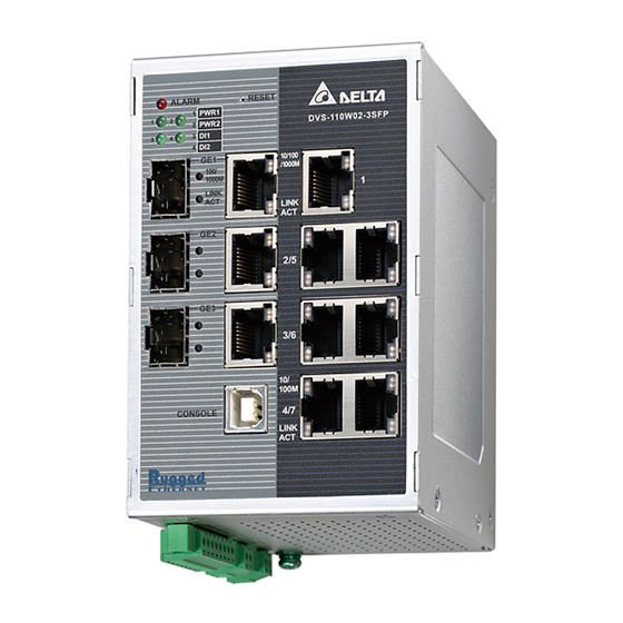
Delta DVS Series, DVS-108W02-2SFP, DVS-109W02-1GE, DVS-110W02-3SFP Manual
- User manual (40 pages) ,
- User manual (173 pages)
Advertisement
Safety information

- This instruction sheet only provides information on electrical specifications, general specifications, installation and wiring.
- The components and the IC on the circuit board can be easily damaged by static electricity; therefore DO NOT touch them before precautions against static electricity are done. To prevent the danger and damage from occurring, people who are not maintenance staff should not operate or accidentally hit the body of the DVS series switch. Besides, DO NOT touch any terminal when the power is switched on.
- This product is equipped with Class 1 LASER/LED components. DO NOT stare directly at the LASER/LED beam to avoid serious injury to your eyes.
- Please read this instruction sheet thoroughly, and follow the instructions to prevent the damage to the device or injury to the staff.
Introduction
The DVS series switches are equipped with the intelligent alarm, digital input function, and allow the wide range of operating temperature (-40 to 75oC). The DVS series switches are designed to support the application in any rugged environment and comply with UL, CE and FCC standards.
Functions
- 10/100Base-T(X) (RJ45), 10/100/1000Base-T (RJ45), 100/1000Base-SFP Fiber
- IEEE 802.3/802.3u/802.3ab/802.3x/802.3z
- Auto-negotiation speed
- Auto-MDI/MDI-X
Package Checklist
- One Delta DVS Managed Ethernet Switch
- Protective Caps for unused RJ45 ports
- Wall mounting Plate x1
- USB Type A to Type B console cable x1
- User manual and software CD
- Instruction Sheet
Installation
- DIN-Rail Mounting
| Mounting Step 1: Hook the upper end of the DIN clip of the DVS series switch on the DIN-Rail. Step 2: Lightly push the DVS series switch toward the DIN-Rail until they contact each other closely. | Removal Step 1: Insert the flat-blade screwdriver into the DIN clip and pull the DIN clip downward. Step 2: Pull the DVS series switch, and you can remove it from the DIN-Rail. |
 |  |
- ƒWall Mounting

- Insert the wall mounting bracket into the slot on the rear panel of the DVS series switch, and tighten the screw on it, as shown in the diagram below.
- Place the wall mounting bracket in an appropriate position, and tighten the two screws on the bracket and the DIN clip.

Wiring the Redundant Power Input
The DVS series switches are equipped with one to two sets of DC input (PWR1 / PWR2). Both sets of DC input can be connected to a wide range of power sources (12 to 48VDC). If one power source fails, the other live source can work as a backup to ensure that the machine operates normally.

- Insert the negative and positive DC wires into the terminal block, and make sure that the positive DC wire is connected to V1+ or V2+, and that the negative DC wire is connected to 0V.
- To prevent the loose DC wires, tighten the wire clamp screws on the terminal block connector with the flat-blade screwdriver.
NOTE: Please use copper wire 60/75oC, conductor 16 to 24 AWG; screw up at torque 2.2kgf-cm(1.91 in-lbs) Step 3: Insert the plastic terminal block connector into the terminal block receptor on the DVS series switch.

NOTE: Grounding the ground terminal on the DVS series switch can avoid the noise effect due to the electromagnetic interference (EMI).
 | Please use Class 2 power sources. |
| The devices are designed for operation with a LPS power supply of "12 to 48VDC, 1A power rating" in accordance with EN 60950-1 ed.2. The devices is intended to be operated under altitude up to 10,000ft(3048m), the DC power supply source comply with the requirement of 10,000ft(3048m) of clearance is multiplied by the altitude correction factor(1.15), specified in table A.2 of IEC 60664-1, 1992+A1:2000. |
Wiring the Alarm Contact
The DVS series switches are equipped with one to two sets of alarm (Alarm1 / Alarm2).The alarm contact is a dry relay. If one of the two power sources fails, one of digital input is triggered or the communication is interrupted, the contact will turns from an "OPEN" circuit to a "CLOSED" circuit. The relay can be connected to a 5A/24VDC power source.

Wiring the Digital Input
The DVS series switches are equipped with one to two sets of digital input (DI1 / DI2). If the power source between 0 to 5V, the state of DI is OFF. If the power source between 11 to 30V, the state of DI is ON. The maximum input current is 6mA.

 | The electrical circuit of DI1 and DI2 are independent, so you don't need to care about NPN type or PNP type of DI. If the electrodes positive and electrodes negative of DI has been reversed when you plug the cable, DI still can work properly. |
LED Indicators
- DVS-108W02-2SFP / 109W02-1GE / 110W02-3SFP
LED Color Status Description ALARM Red ON The communication is interrupted, there is a power failure, or alarm event which has been configured happened. OFF The communication is not interrupted, there is no power failure, or alarm event which has been configured doesn't happen. PWR1/ PWR2 Green ON The power is supplied normally. OFF The power is not supplied. DI1/DI2 Green ON The DI is triggered. OFF The DI is not triggered. 10/100M (RJ45) Orange ON The port is connected at a speed of 10 or 100 Mbps. OFF The port is disconnected. 10/100/1000M (RJ45) Green ON The port is connected at a speed of 1000 Mbps. Orange ON The port is connected at a speed of 10 or 100 Mbps. OFF The port is disconnected. 100/1000M (SFP Fiber) Green ON The port is connected at a speed of 1000 Mbps. Orange ON The port is connected at a speed of 100 Mbps. OFF The port is disconnected. LINK/ACT
Green
ON The Network communication connection has been established. Blinking The data is being transmitted. OFF The Network communication connection has not been established. R.M/CPLG.R
Yellow
ON As a master of ONE RING, or a forwarding path of Coupling Ring. Blinking Any node disconnection is occurred in ONE RING or Coupling Ring. OFF A slave of ONE RING, or ONE RING or Coupling Ring is not available. C.HD/C.TL
Green
ON As a head or a tail of ONE CHAIN. Blinking As a head or a tail of ONE CHAIN, any node disconnection is occurred. OFF ONE CHAIN is not available.
Ethernet Interface
- 10/100Base-T(X), 10/100/1000Base-T Connection
The 10/100Base-T(X) or 10/100/1000Base-T ports of the DVS series switches are used to connect to Ethernet. RJ45 ports support MDI (NIC–type) and MDI-X (HUB/Switch-type) modes, the pin definition of the Ethernet cable is as follows.
| 10/100Base-T(X) | 1000Base-T |  | ||
| PIN | MDI Mode | MDI-X Mode | MDI/MDI-X Mode | |
| 1 | Tx+ | Rx+ | TP0+ | |
| 2 | Tx- | Rx- | TP0- | |
| 3 | Rx+ | Tx+ | TP1+ | |
| 4 | n.c. | n.c. | TP2+ | |
| 5 | n.c. | n.c. | TP2- | |
| 6 | Rx- | Tx- | TP1- | |
| 7 | n.c. | n.c. | TP3+ | |
| 8 | n.c. | n.c. | TP3- | |
- 100/1000Base-SFP Fiber Connection
Each SFP module has TX and RX interface, make sure the fiber connect TX interface to RX interface between two SFP modules.


Mechanical Characteristics
| DVS-108W02-2SFP | DVS-109W02-1GE | DVS-110W02-3SFP | |
| Case | IP40 Aluminum metal case | ||
| Dimension(mm) | 145.3 (H) x 75(W) x 108.2(D) | ||
| Weight(g) | 520 | 500 | 564 |
For more information about the product, please visit http://www.deltaww.com
Documents / Resources
References
Download manual
Here you can download full pdf version of manual, it may contain additional safety instructions, warranty information, FCC rules, etc.
Download Delta DVS Series, DVS-108W02-2SFP, DVS-109W02-1GE, DVS-110W02-3SFP Manual
Advertisement


Need help?
Do you have a question about the DVS Series and is the answer not in the manual?
Questions and answers