Table of Contents
Advertisement
Quick Links
Instructions - Parts
InvisiPac
HM25 and HM50 Tank-Free
Hot Melt Delivery System
For delivering and dispensing hot melt adhesive pellets. For professional use only.
Not approved for use in explosive atmospheres or hazardous locations.
1200 psi (8.3 MPa, 83 bar) Maximum Working Pressure
400°F (204°C) Maximum Fluid Operating Temperature
100 psi (0.7 MPa,7 bar) Maximum Air Inlet Pressure
Important Safety Instructions
Read all warnings and instructions in this
manual and in the applicator and hose manu-
als. Save all instructions.
™
™
333347F
9902471
Certified to
CAN/CSA C22.2 No. 88
Conforms to
ANSI/UL 499
EN
Advertisement
Table of Contents
Troubleshooting

Related Manuals for Graco 24T918


Summary of Contents for Graco 24T918
- Page 1 Instructions - Parts ™ InvisiPac ™ HM25 and HM50 Tank-Free 333347F Hot Melt Delivery System For delivering and dispensing hot melt adhesive pellets. For professional use only. Not approved for use in explosive atmospheres or hazardous locations. 1200 psi (8.3 MPa, 83 bar) Maximum Working Pressure 400°F (204°C) Maximum Fluid Operating Temperature 100 psi (0.7 MPa,7 bar) Maximum Air Inlet Pressure Important Safety Instructions...
-
Page 2: Table Of Contents
Software Update Procedure ..... . 77 Graco Information ....... . 130... -
Page 3: Related Manuals
Related Manuals Related Manuals Manuals are available at www.graco.com. Component manuals in English: Part Description 3A2805 InvisiPac GS35 Hot Melt Applicator Instruc- tions - Parts 332072 InvisiPac Heated Hose Instructions - Parts 333348 HM50 Fuse Kit, Instructions-Parts 333349 InvisiPac 480V Transformer Upgrade Kit,... -
Page 4: Models
2 wire and PE • 3-Phase without Neutral • 200-240VAC 50/60 Hz 200-240 VAC Δ / PE 24T918 • 3 wire and PE • 3-Phase with Neutral • 350-415 VAC Line to Line 350-415 VAC Y 50/60 Hz / Neutral / PE •... -
Page 5: 200-240 Vac, 350-415 Vac Hm25 Models
Models 200-240 VAC, 350-415 VAC HM25 Models See 400 VAC Transformer models on page 6. See 480 VAC Transformer models on page 7. Model Channels Voltage Type Description Frequency Amps • 1-Phase • 200-240VAC 200-240 VAC 50/60 Hz / PE •... -
Page 6: 400 Vac Transformer Hm25 Models
Models 400 VAC Transformer HM25 Models Model Channels Voltage Type Description Frequency Amps • 3-Phase without Neutral • 335-400 VAC Line to Line 24V426 335-400 VAC 50/60 Hz / PE • 3 wire and PE • 3-Phase without Neutral • 335-400 VAC Line to Line 24V427 335-400 VAC... -
Page 7: 480 Vac Transformer Hm25 Models
Models 480 VAC Transformer HM25 Models Model Channels Voltage Type Description Frequency Amps • 3-Phase without Neutral • 400-480 VAC Line to Line 24V429 400-480 VAC 50/60 Hz / PE • 3 wire and PE • 3-Phase without Neutral • 400-480 VAC Line to Line 24V430 400-480 VAC... -
Page 8: Warnings
Warnings Warnings The following warnings are for the setup, use, grounding, maintenance, and repair of this equipment. The exclama- tion point symbol alerts you to a general warning and the hazard symbols refer to procedure-specific risks. When these symbols appear in the body of this manual or on warning labels, refer back to these Warnings. Product-specific hazard symbols and warnings not covered in this section may appear throughout the body of this manual where applicable. - Page 9 Warnings WARNING EQUIPMENT MISUSE HAZARD Misuse can cause death or serious injury. • Do not operate the unit when fatigued or under the influence of drugs or alcohol. • Do not exceed the maximum working pressure or temperature rating of the lowest rated system component.
- Page 10 Warnings WARNING PERSONAL PROTECTIVE EQUIPMENT Wear appropriate protective equipment when in the work area to help prevent serious injury, including eye injury, hearing loss, inhalation of toxic fumes, and burns. This protective equipment includes but is not limited to: • Protective eyewear, and hearing protection.
-
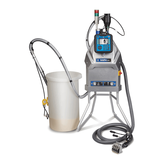
Page 11: Component Identification
Component Identification Component Identification Key: Advanced Display Module (ADM) Electrical Enclosure Pump Air Pressure Regulator Pump Air Pressure Gauge Vacuum Transfer Air Pressure Regulator Vacuum Transfer Air Pressure Gauge Shaker Tube G1 Shaker Head G2 Vacuum Transfer Tube G3 Vacuum Transfer Inlet Funnel G4 Vacuum Transfer 3/8 in. -
Page 12: Heated Fluid Manifold
Component Identification Heated Fluid Manifold NOTE: System shown with plastic and metal shrouds removed. Key: Electrical Enclosure Front Access Door Melter W1 Drain Port W2 Drain Tray Inlet Filter (Low Pressure - Before Pump) Outlet Filter (High Pressure - After Pump) Adhesive Pellets Level Sensor (not shown;... -
Page 13: Electrical Enclosure
Component Identification Electrical Enclosure Key: Multi-Zone Low Power Temperature Control Module (MZLP) AC Incoming Power Connection AF Chassis Ground AG Automatic Wiring Board (AWB) 333347F... -
Page 14: Advanced Display Module (Adm)
Component Identification Advanced Display Module (ADM) User Interface NOTICE To prevent damage to soft key buttons, do not press the buttons with sharp objects such as pens, plastic cards, or fingernails. NOTE: See Appendix A - ADM on page 114 for com- plete ADM operation details. - Page 15 Component Identification Screen Components Screens Order Current date and time Operating Mode Faults, Status Melter Heating Status Melter Actual Temperature Hose and Applicator Heating Status Hose Actual Temperature Applicator Actual Temperature . 6: Main Screen Components Operating Mode Description Component Status •...
- Page 16 Component Identification 333347F...
-
Page 17: Setup
Electric or static sparking can cause fumes to ignite or explode. If installing the system in place of a non-Graco hot melt Improper grounding can cause electric shock. Ground- system, purchase Adapter Plate, 24R083. See ing provides an escape wire for the electric current. - Page 18 To install the InvisiPac system in place of a • non-Graco hot melt system, purchase Adapter Plate, 24R083. See installation instructions on page 102. To raise the system to eye-level, purchase System •...
- Page 19 Setup NOTE: In the following steps, when routing the vacuum ties (G5). See F . 10. transfer hose, ensure there are no tight coils, turns, or 10. If desired, secure the 1.3 in. (33 mm) clear vacuum dips in the vacuum hose. These will inhibit optimal func- transfer tube (G2) and 3/8 in.
- Page 20 15. Install applicator(s), see F . 11: b. Use a 1/4 in. allen wrench to remove the drain NOTE: Use of a Graco applicator is not required with port plug (W1). See F . 11. this system. However, all applicators attached to the system must be rated for 1200 psi (8.3 MPa, 83 bar),...
- Page 21 17. Install the supplied air inlet bleeding ball valve and air filter kit (Graco Part No. 24R707) at the 1/4 NPT female system air inlet (J). See F . 12.
-
Page 22: Recommended Air Setup
80-100 psi 30 scfm capacity (5.5-6.8 bar, 0.55-6.8 MPa) 30 scfm capacity. Ensure funnel air is connected Air Filter/Ball Valve at System Air Inlet (Graco Kit 24R707, included) Vacuum Pump Vacuum: 40 - 80 psi (2.8-5.5 bar, Pump: 0.28-0.55 MPa);... -
Page 23: Connect Electrical Cord
Setup Connect Electrical Cord 5. Attach insulated ferrules to the end of each wire. NOTE: See Grounding section on page 17. Improper wiring may cause electric shock or other serious injury if work is not performed properly. Have a qualified electrician perform any electrical work. Be sure your installation complies with all National, State and Local safety and fire codes. -
Page 24: 208V Electrical Circuits
Setup 208V Electrical Circuits NOTE: An incorrect RTD setting will cause the system to be incapable of maintaining the temperature setting. For 208V electrical supply, a qualified electrician can NOTE: The supported RTD types are Ni, 100 ohm; Ni, install a 208V to 240V step-up transformer to improve 120 ohm;... - Page 25 Setup 6. On the Advanced 2 screen, set the temperature and 9. Press to switch from the Setup screens to the mass units. Operation screens. Use , and navigate between screens. 10. On the Targets screen, use , shown next to , to adjust system melter setting.
-
Page 26: Applicators
Setup NOTE: Alternatively, use the physical up and down 11. On the Targets screen, adjust heated hose and applicator temperature settings: arrow push-buttons on the ADM keypad until next to the temperature setting to change then use the NOTE: InvisiPac is a high powered tank-free system numeric keypad to enter the desired temperature. -
Page 27: Plc Connection
Setup PLC Connection NOTE: The InvisiPac system ships with two screw-ter- minal connectors that plug into MZLP connectors H1 and H2. Connectors are located in a bag on the inside of the electrical enclosure front access door. To replace the connectors, order kit 24P176. A PLC can control and monitor all items shown in the 1. - Page 28 Setup PLC Connection Block Diagrams The following block diagrams show how to connect customer inputs and outputs to the InvisiPac MZLP. For conve- nience, each InvisiPac ships with connector kit 24P176. If a connector is lost or damaged, order kit 24P176 for replacements.
-
Page 29: Operation
Operation Operation Initial Startup and Prime Heating and dispensing hot melt adhesive may create potentially harmful vapors. Read material manufac- turer’s warnings and material MSDS to know specific NOTE: All setup procedures must be completed prior to hazards and precautions. Ventilation of the work area initial startup. -
Page 30: Manual Refill
Operation 10. On new systems only: After the melter has reached 6. Use pump air pressure regulator (C) to adjust pump 250°F (121°C) and the funnel is filled with pellets, air pressure to 0. set the melter temperature back to the desired oper- ating temperature. -
Page 31: Automatic Refill
Operation It is recommended to maintain a minimum flow rate of 5. Refill the funnel as needed to maintain the required 1.5 lb/hour to prevent material from melting within the dispense rate. feed cap and funnel. If production rate is below 6. -
Page 32: Dispense
Operation 4. If not already set, use vacuum transfer air pressure e. Verify applicators are closed. regulator (E) to adjust vacuum transfer air pressure setting to 40-100 psi (280-690 kPa, 2.8-6.9 bar). 4. Press to enable the heaters and pump. Recommended setting is 60 psi (414 kPa, 4.1 bar). -
Page 33: Shutdown
Operation Shutdown Enable Schedule Function The Schedule function is automatically enabled when Press to disable the heaters and pump. The values are entered in the Schedule screen. To disable a screen will say “Inactive”. If using the Schedule function, scheduled event, navigate to the event and press the heaters and pump will be disabled automatically at The event will appear gray on the screen when it is dis- the set time. -
Page 34: Drain The System
Operation Drain the System 12. Wait until system stops draining or at most 10 min- utes. NOTE: There will be some residual adhesive in the sys- tem. NOTE: The system must be drained prior to flushing 13. When done performing the procedure that required and prior to some maintenance and repair procedures. - Page 35 Operation 5. On the System 3 screen (in the Setup screens), ver- 12. If heating system is disabled, press to enable ify the Refill Setting is set to “Manual”. the heaters and pump. 13. Wait for the melter temperature to reach the hot melt cleaning fluid manufacturer’s recommended temperature.
-
Page 36: Operation Tips To Minimize Charring
Operation Operation Tips to Minimize 25. Install fill cap onto melter rubber housing. Charring 26. Slide funnel assembly through air motor bracket then tighten clamp. Set the Pump Idle Time to System Inactive function 27. On the System 3 screen (in the Setup screens), set on the System 3 screen to lowest value that will not the Refill Setting to “Auto”. -
Page 37: Maintenance
Maintenance Maintenance 6. Insert allen wrench through the outlet filter cap to lift outlet filter (236) out of the system. 7. Discard outlet filter assembly. Replace Outlet Filter 8. Place o-rings (232, 237) provided with new outlet fil- The outlet filter is designed to prevent small contami- ter onto new outlet filter (236). -
Page 38: Replace Funnel Filter
Maintenance 4. When the melter temperature is the desired tem- 9. Slide new screen (213) into melter base perature, turn main power switch OFF. manifold (201). 5. Disconnect cable from ADM, push cable through 10. Install filter cap (215) then use a 1 in. socket to plastic shroud, then remove plastic shroud from sys- tighten. -
Page 39: Filter Maintenance Guidelines
To estab- lish a preventative maintenance cycle tailored to your environment, Graco recommends inspecting filters every 4 weeks after installation and replacing when necessary. Document replacement intervals and use this as your preven- tative maintenance schedule moving forward. -
Page 40: Troubleshooting
Troubleshooting Troubleshooting To avoid injury due to unexpected machine operation initiated by a remote controller, disconnect the cus- tomer I/O cable from the system prior to troubleshoot- ing. ADM Error Code Table When an error occurs, press to acknowledge the error. If a Maintenance error occurs, navigate to the Mainte- nance screen and press to clear the error. - Page 41 Troubleshooting Code Description Type Cause Solution A3MF High Fan Cur- Devia- Transformer fan is greater than Replace transformer fan. rent, Trans- tion 600mA. former A4D0 High Current Alarm Defective or shorted to ground on the Measure resistance to ground between heater Melter band heater or rod heater.
- Page 42 Troubleshooting Code Description Type Cause Solution CAC_ Comm Error Alarm System not responding to ADM. Dial not set correct on MZLP. Set to 1 on board 1=MZLP 1 Module with daughter board. Set to 2 on MZLP without 2=MZLP 2 the daughter board in center of electrical enclo- 3=MZLP 3 sure.
- Page 43 Troubleshooting Code Description Type Cause Solution L8FX Refill timeout Alarm Melter did not receive enough adhesive Storage bin out of adhesive. Refill adhesive. pellets for flow rate. Plugged inlet feed hose or funnel. Clear plugged hose or funnel. Low air pressure on feed regulator. Check regu- lator.
- Page 44 Troubleshooting Code Description Type Cause Solution T4D0 High Temp Alarm Melter continues to raise above the set- Check that RTD is seated in melter correctly. Melter point. Check that overtemperature switch is plugged in and check switch resistance. The switch resis- tance should be near 0 Below 400°F (204°C).
- Page 45 Troubleshooting Code Description Type Cause Solution T8D_ No Temp Rise in Alarm Temperature reading does not change. Check fuses F5 and F6 (channels 1, 3, 5) or F9 Hose (all zones) and F10 (channels 2, 4, 6) on the MZLP that con- trols the error channel.
-
Page 46: Mechanical And Electrical Troubleshooting
Troubleshooting Mechanical and Electrical Troubleshooting Problem Cause Solution Refill Timeout The system was unable Check hopper for adequate material and material blocking. Error to refill in less than 30 Verify the vacuum transfer system air pressure is 40-80 psi (60 psi rec- seconds. - Page 47 Troubleshooting Problem Cause Solution Level Sensor Failure of the level sen- Check sensor cable J14 to level sensor (20). Error sor (20) or sensor Enable Diagnostic screen on ADM then check sensor readings on the cable 16T108 (J14 to Diagnostic screen. Sensor readings should be about 4.3V if melter is level sensor (20)).
- Page 48 Troubleshooting Problem Cause Solution To prevent data loss, download system data. See Appendix B - USB USB Log Full The InvisiPac system Downloading, Uploading on page 120. will display this notifica- tion when the USB data logs reach 90% full. The InvisiPac This error generally This can occur if the melt rate for the system is exceeded, resulting in...
- Page 49 Troubleshooting Problem Cause Solution 1. If the cycle rate is below (11 cpm - HM25, 22 cpm - HM50) and the Unable to The InvisiPac system system is still running away increase the InvisiPac system achieve pub- monitors temperature temperature in small increments over the current set point, leave lished melt rate within aluminum mass hoses and applicators at desired set point.
- Page 50 Troubleshooting Problem Cause Solution Slow start-up Wrong setting in ADM Wrong breaker setting on ADM in the breaker setting in the setup time or system breaker setup. screen. takes longer Low incoming voltage. Incoming voltage should be 200-240VAC for a 230 volt unit and 380- than 10 min- 400 VAC for a 400 volt unit.
- Page 51 Troubleshooting Problem Cause Solution No adhesive or Plugged applicator Replace applicator manifold filter. Graco applicator manifold filter in incorrect manifold filter. bottom of manifold or inline filter on other applicators. amount of Clogged hose. Flush or replace hose. adhesive out-...
- Page 52 Troubleshooting Problem Cause Solution Adhesive flow- Failed valve in the open Replace dispense module. ing out of position. one/some Adhesive pressure too Reduce air pressure to air motor. applicators high. when not trig- gered Applicator will Heat rod failure in appli- Check resistance on heater rods.
- Page 53 Troubleshooting Problem Cause Solution Static shock Ground wire not in Attach a ground wire from the shaft of the shaker unit to a true earth when touching place on shaker ground. Order shaker grounding kit 24R708. shaker or assembly. Some adhe- adhesive bin.
- Page 54 Troubleshooting Flush Pressure Relief Valve Check the Pump Air Solenoid Operation Perform this procedure when directed in the Trouble- Perform this procedure when directed in the Trouble- shooting table. shooting table. NOTE: System must be up to operating temperature for 1.
-
Page 55: Mzlp Troubleshooting
Troubleshooting MZLP Troubleshooting MZLP ti20348a . 30: MZLP Diagnostic LED Location . 29: MZLP LED Signals NOTE: The MZLP LED is located on the inside of the electrical enclosure. To view, remove the electrical enclosure front access door. Signal Description Green On MZLP is powered up and input voltage is within operating con-... -
Page 56: Repair
Repair Repair NOTE: Some procedures require special tools. Read Disassembly (see F . 31): through each procedure prior to beginning it to ensure 1. Flush the system. See page 34. you have the required tools to complete the entire pro- cedure. - Page 57 Repair c. Install piston valve (222) onto piston rod (223). 6. Slide throat bearing (233) over the piston rod (223). Use socket and tap with a rubber mallet to press Torque to 24-30 ft-lb (33-41 N•m). throat bearing (233) into place and seat the throat u-cup.
- Page 58 Repair Replace Pump Inlet Housing Checks without a socket to install and tighten foot valve (230) onto melter. 2. Apply anaerobic thread sealant on threads of four bolts (246) and connect pump to melter outlet. Torque to 12-18 ft-lb (16-24 N•m). Replace Pump Cylinder Seals and Piston Seals .
- Page 59 Repair 5. Remove air lines from relief valve (245) and air 14. Remove and discard cylinder seals (217). See F motor (218) See F . 31 on page 56. 6. Remove nuts (3) securing melter shield (27) in Reassembly: place then remove melter shield. See F .
-
Page 60: Melter
Repair Melter 6. Remove screws (8) then remove electrical enclo- sure front access door (10). Remove Melter Assembly 7. Disconnect heater rod wires from J4 connector on AWB board. 8. Remove the air tube (36) from the relief valve (245). Pull the air tube from the metal shroud (27). - Page 61 Repair 21. Remove all heater wires from the following termi- 5. Group the 4 sets of heater wires together and run nals. Pull wires up through the rubber grommet on them through the grommet on the top of the electri- the top of the electrical enclosure (1).
- Page 62 Repair Replace Band Heater 8. Locate the J4-1 and J4-2 wires in AWB board and remove wires. 9. Pull wires up through grommet (63) on top of the electrical enclosure (1). Clip any wire ties that hold the wires in place. 10.
- Page 63 Repair Replace Band Heater Temperature Sensor Reassembly (see F . 42): 1. Route new harness wires through grommet (63) in the top of the electrical enclosure. 2. Connect wire connectors to over-temperature switch (251). See F . 43 on page 64. 3.
- Page 64 Repair Replace Heater Over-Temperature Switch 5. Feed ADM cable through shroud then install shroud and connect cable to ADM. 6. Open system air inlet ball valve. 7. Turn main power switch ON. Replace Heater Rod ti21052a . 43 Disassembly (see F .
- Page 65 Repair 4. If removing the pump heater rod (210): 5. If replacing pump heater rod (210), feed ADM cable through shroud then install shroud and connect a. Remove the air tube (36) from the relief cable to ADM. valve (245). Pull the air tube through the metal 6.
- Page 66 Repair 6. Use crescent wrench to remove melter fluid pres- sure relief valve (245). See F . 45. 7. Use an o-ring pick to remove o-ring (244). 8. Install o-ring (244) into manifold. NOTICE To prevent damage to o-ring, ensure o-ring is seated properly prior to moving to next step.
-
Page 67: Multi-Zone Low Power Temperature Control Module (Mzlp)
Repair Multi-Zone Low Power Temperature Control Module (MZLP) Replace MZLP Fuse Fuse Part 24V510 MZLP Fuses F1, F2 250VAC, 25A, fast acting, white, 0.25 in x 1.2 in F3-F10 250VAC, 8A, fast acting MZLP Identification Fuse Kits 24V510 MZLP Description 24V289 24V510 Includes standard clear fuses. - Page 68 Repair Replace MZLP 2. Apply channel label stickers to new MZLP. See F 3. Use four screws (114) to install MZLP (112) to elec- trical enclosure (1). Disassembly: 4. Reconnect cables to MZLP (112). 1. Turn main power switch OFF. NOTE: Do not force the electrical connection.
-
Page 69: System
Repair Reassembly: 3. Gently pull up on cable while unscrewing fill sensor connector then remove fill sensor cable from fill 1. Plug new daughter card (112a) into the MZLP (112). sensor (20). 2. Use screws (112b) to secure daughter card to 4. - Page 70 Repair Replace AWB Reassembly: 1. Use two screws (144) to secure power supply bracket (145) to new AWB (143). See F . 51. 2. Mount power supply (146) to power supply bracket (145). See F . 51. 3. Connect connector (labeled AWB-J1) on power sup- ply harness (147) to J1 on AWB (143).
- Page 71 Repair Replace Power Supply Replace Power Supply Harness Disassembly: Disassembly: 1. Turn main power switch OFF. 1. Turn main power switch OFF. 2. Remove electrical enclosure front access door (10). 2. Remove electrical enclosure front access door (10). 3. Remove power supply (146) from power supply 3.
-
Page 72: Air Controls
Repair Air Controls Replace Air Control Solenoids NOTE: In order to replace the air control solenoids, the system must be tipped back to access underneath the electrical enclosure. Disassembly (see F . 52): 1. Turn main power switch OFF. 2. Disconnect plug from power outlet or turn off circuit breaker for incoming power. -
Page 73: Air Motor
Repair 6. Install electrical enclosure front access door. 3. Place one small crescent wrench on the brass part of the gauge then use a second small crescent Replace Air Control Gauge wrench to tighten the air fitting (403b). NOTICE In the following step, do not overtighten the two nuts (403a). - Page 74 Repair Replace Air Valve d. Torque pilot valve to 95-105 in-lb (10.7-11.9 N•m). 4. Replace bottom pilot valve (511): . 57 Disassembly (see F . 57): 1. Close the bleed-type ball valve installed at the system air inlet to relieve all air pressure in the system.
- Page 75 Repair 3. Use 10 mm socket to torque screws (509) to b. Remove dowel pin (238). 95-105 in-lb (10.7-11.9 N•m). c. Remove three screws (240). 4. Install fill cap then tighten upper hose clamp on rub- ber housing. d. Remove screws (8), screws (74), and bracket (82).
-
Page 76: Transformer Fan
Repair Transformer Fan 5. Remove screws (157) and fan grill (154). Pull two fan wires down into the transformer enclosure. 6. Cut three zip ties on corrugated tube (167) and two zip ties (161) on fan grill (154). Replace Fan 7. -
Page 77: Software Update Procedure
Repair Software Update Procedure NOTE: When the screen turns on, you will see the fol- lowing screens: When software is updated on the ADM the software is First: then automatically updated on all connected GCA com- Software is checking ponents. A status screen is shown while software is which GCA modules updating to indicate progress. -
Page 78: Electrical Schematics
Electrical Schematics Electrical Schematics Cable Identification Use the table to identify cables and other system com- To prevent electric shock and system damage, all ponents in the electrical schematics. electrical work must be performed by a qualified elec- trician. Part Description Incoming Power Manifold, air assembly... -
Page 79: System
Electrical Schematics System Transformer TEMP TEMP Option TEMP TEMP To MZLP #2 4 and 6 FAN - FAN - FAN + FAN + Channel Option, see page 108 and 110. Band Pump Melter Base Ground Stud DC OK DC OK MZLP 1 112A 1201... -
Page 80: 480Vac Transformer Option
Electrical Schematics 480VAC Transformer Option TEMP TEMP TEMP TEMP FAN - FAN - FAN + FAN + Typical Hose / Applicator Wiring MZLP1 HEATER T° T° OVER HOSE HOSE TEMP HEATER 333347F... -
Page 81: 2Nd And 3Rd Mzlp Options
Electrical Schematics 2nd and 3rd MZLP Options MZLP3 MZLP 2 MZLP 1 333347F... -
Page 82: Air Schematic
Air Schematic Air Schematic NOTE: Install an optional ramp up/down controller to limit air to the air motor and slow down the system dis- pense rate. 333347F... -
Page 83: Parts
Parts Parts InvisiPac Systems System Parts, Page 1 of 3 Apply door gaskets (11) to door (10) per layout diagram. Apply pipe sealant to all non-swiveling pipe threads. Bottom sensor (20) out then back off 1/2 turn. Lubricate all seals and o-rings with water resistant grease. Torque to 5-11 ft-lb (7-15 N•m). - Page 84 Parts System Parts, Page 2 of 3 333347F...
- Page 85 Parts System Parts, Page 3 of 3 48 in. (1219 mm) 48 in. (1219 mm) 16 in. (406.4 mm) 48 in. 48 in. (1219 mm) (1219 mm) 8 in. (203 mm) 2 in. (50.8 mm) 13 in. 330.2 mm) 333347F...
- Page 86 Parts System Parts Quantities HM50 HM25 2 Channel 4 Channel 6 Channel 2 Channel 4 Channel 6 Channel Part Description ENCLOSURE, electrical 115942 NUT, hex, flange head 167002 INSULATOR, heat 24V169 SYSTEM, melter, HM25 24V542 SYSTEM, melter/pump, HM50 16V540 GUARD, insulated INSULATOR, wrap TRAY, drip 8†...
- Page 87 Parts Quantities HM50 HM25 2 Channel 4 Channel 6 Channel 2 Channel 4 Channel 6 Channel Part Description GROMMET, 1/4 ID BUSHING, strain relief GROMMET, tube GROMMET, tube 43▲ 16Y781 LABEL, safety 16U007 LABEL, InvisiPac, HM25 LABEL, InvisiPac HM50 LABEL 47✖...
- Page 88 Parts Quantities HM50 HM25 2 Channel 4 Channel 6 Channel 2 Channel 4 Channel 6 Channel Part Description 80★ CLAMP, hose, spacer 81★ CLAMP, hose, spacer 82† BRACKET, funnel, HM25 BRACKET, HM50, funnel, mounting 123986 FITTING, elbow, 3/8 OD tube 1 GROMMET 122030 CABLE, gca, m12-5p...
-
Page 89: Electrical Enclosure
Parts Electrical Enclosure MZLP 3 MZLP 112a 106, 107 MZLP 2 Apply sealant to all non-swiveling pipe threads. Set rotary switch to “1” on MZLP with daughter card. Set rotary switch to “2” on MZLP 2. Set rotary switch to “3” on MZLP 3. 333347F... - Page 90 Parts Electrical Enclosure Parts Quantity 1 MZLP 2 MZLP 3 MZLP 1 MZLP 2 MZLP 3 MZLP Part Description No Transformer 400/480 V Transformer CABINET, controls 122030 CABLE, gca, m12-5p HARNESS, MZLP1, AWB 123970 SWITCH, disconnect, 40a 126839 CONTACT, n-pole 120858 BUSHING, strain relief, m40 thread 120859...
- Page 91 Parts Quantity 1 MZLP 2 MZLP 3 MZLP 1 MZLP 2 MZLP 3 MZLP Part Description No Transformer 400/480 V Transformer 16T103 CABLE, pump ◆ SENSOR, rtd, 1m 16T108 CABLE, ultrasonic, m12-4p, 1m HARNESS, MZLP 2, awb HARNESS, MZLP 2/3, awb 114958 STRAP, tie SCREW, flange, serrated, 10-24 x 0.5...
-
Page 92: Transformer Assemblies
Parts Transformer Assemblies Mount fan with arrow pointing towards grill. Use nut to lock down the ground wire from transformer. Tie down cabling from transformer and fan using cable tie onto Connect black fan wire labeled (-) from transformer (153) in the tie down locations. -
Page 93: Melter And Pump Assembly
Parts Melter and Pump Assembly HM25, 24V169 HM50, 24V542 Lubricate all seals and o-rings with grease. Assemble inserts (252) 0.01-0.05 in. (0.3-1.3 mm) below surface. Orient melter (202) sensor hole in line with band heater (208) Assemble inserts (252) 0.01-0.05 in. (0.3-1.3 mm) below surface. clamp. - Page 94 Parts HM25 Melter and Pump, 24V169 Ref. Part Description Qty. HM50 Melter and Pump, 24V542 243★• RETAINER, seat, dump valve 244★• 15Y627 PACKING, o-ring #2-116, ptfe Ref. Part Description Qty. 245★• VALVE, relief BASE, melter, HM50 246• 121295 SCREW, cap, socket head; 5/16 x BASE, melter, HM50 2.5 in.
-
Page 95: Air Motor, 24V558
Parts Air Motor, 24V558 Apply water-resistant grease. Torque to 95-105 in-lb (10.7-11.9 N•m). Ref. Part Description 24A579 MANIFOLD, medium, short GASKET, cover, small 507† SEAL, air valve, manifold 509† SCREW, m6 x 25, thread forming VALVE, pilot 512† VALVE, air, small 15M213 MUFFLER, 3/8 -- Not for sale. -
Page 96: Feed System Shaker And Tube, 24V507
Parts Feed System Shaker and Tube, 24V507 Apply pipe sealant to threads. ti20738a Parts Part Description 24P861 SHAKER 24N954 TUBE, steel 303†◆ --- TUBE, clear PVC, 1.3 in. (33 mm) OD HOSE, nylon, 3/8 in. OD, 15.5 250 psi (1.7 MPa, 17 bar) 305◆... -
Page 97: Air Controls Assembly
Parts Air Controls Assembly Apply sealant to all non-swiveling pipe threads. Air Controls Assembly Parts Part Description PANEL, air, controls 24V520 CONTROL, air, vacuum trans- fer and pump 15T500 GAUGE, pressure, air, panel mount, 1/8 in. npt 15T498 FITTING, 90 degree, swivel, 5/32 in. -
Page 98: Pressure Relief Valve, 24P856
Parts Pressure Relief Valve, 24P856 611 608 Apply sealant to all non-swiveling pipe threads. Apply grease. Torque to 4-6 in-lb (0.5-0.7 N•m). Part Description BODY, fluid BODY, air 15T413 PISTON, air AIR CAP, valve BEARING, shaft, needle SHAFT, needle, valve SOCKET, ball assembly 608†... -
Page 99: Feed Inlet Funnel, 24V505
Parts Feed Inlet Funnel, 24V505 Ref. Part Description FUNNEL, large mouth BAFFLE, pellet O-RING, fluoroelastomer, 160 FUNNEL, insert 24V506 FILTER, feed FUNNEL, filter cover 113161 SCREW, flange, hex hd SCREW, #10-16, thread forming BRACKET, funnel, mounting HOUSING, sensor --- Not for sale. 333347F... -
Page 100: Accessories
Accessories Accessories Special Tools These special tools are designed to make system repairs as easy as possible while ensuring that parts do not get damaged. Part Purpose Part Purpose 1301* Remove Cylinder 1304** Install Rod - Female 1302* Install Cylinder - Female 1305** Install Rod - Male 1303*... -
Page 101: Non-Graco Applicator Adapter Cables
Non-Graco Applicator Adapter Air Adjustment Lock, 24R084 Cables Panel enables locking access to the air adjustment screws. 16T916: For connecting to non-Graco applicators that use a rectangular, 6-pin connector. ti21128a 16T917: For connecting to non-Graco applicators that use a circular, 9-pin connector. -
Page 102: System Stand, 24R088
Accessories System Stand, 24R088 Adapter Plate, 24R083 Use the stand to mount the system at eye level. When Use this adapter plate to install InvisiPac in place of an the system is mounted on the stand, the ADM is 45 in. existing hot melt applicator system. - Page 103 Accessories 333347F...
-
Page 104: 30 Gallon Vibrating Hopper, 24R136
Accessories 30 Gallon Vibrating Hopper, 24R136 Hopper includes a shaker to ensure the adhesive pellets maintain a level surface at all times. Without this, the adhe- sive pellets can stick together, preventing them from continuously covering the vacuum transfer system’s inlet. This would cause the vacuum transfer system to be unable to transfer the adhesive pellets. - Page 105 Accessories 30 Gallon Vibrating Hopper Installation See F . 64 for illustration of installed vibrating hopper. 1. Turn main power switch OFF. Splitter fitting 2. With the steel shaker rod fully assembled and the 3/8 in. OD air line connected to the shaker head, cut the 3/8 in.
-
Page 106: Light Tower Kit, 24R226
Accessories Light Tower Kit, 24R226 The light tower enables someone away from the system to quickly see whether the system is inactive or OFF (no lights), warming up (flashing green), at temperature (solid green), or has an active error (red). 1201 1201a 1203... -
Page 107: Air Reservoir Kit, 16W366
Accessories Air Reservoir Kit, 16W366 Light Tower Kit Installation This kit allows the system to operate as low as 60 psi (0.4 MPa, 4 bar). 1. Turn main power switch OFF. 2. Disconnect cable from ADM, push cable through plastic shroud, then remove shroud from system. 3. -
Page 108: Channel Upgrade Kit, 24V528
Accessories 4 Channel Upgrade Kit, 24V528 Use this kit to upgrade a 2 channel system to a 4 channel system. 1307 1306 1301 1308 1304 1308 1302 1305 Part Description 1301 MODULE, GCA, MZLP 1302 16T087 CABLE, jumper, male/male, 21 in. 1303 HARNESS, 2nd MZLP power 1304... - Page 109 Accessories 4 Channel Upgrade Kit Installation 1. Disconnect plug from power outlet or turn off circuit 6. Remove electrical enclosure front access door. breaker for incoming power. NOTE: Do not force the electrical connection. Minimal 2. Place grounding wrist strap (1304) over your wrist force is required to seat the connector.
-
Page 110: Channel Upgrade Kit, 24V529
Accessories 6 Channel Upgrade Kit, 24V529 Use this kit to upgrade a 4 channel system to a 6 channel system. 1304 1308 1302 1307 1306 1303 1305 1301 Part Description 1301 MODULE, GCA, MZLP 1302 16T087 CABLE, jumper, male/male, 4 in. 1303 112190 STRAP, wrist, grounding 1304... - Page 111 Accessories 6 Channel Upgrade Kit Installation NOTE: Do not force the electrical connection. Minimal 1. Disconnect plug from power outlet or turn off circuit breaker for incoming power. force is required to seat the connector. If resistance is felt, stop and verify the connector orientation. 2.
-
Page 112: Invisipac Adm Simulator Kit, 24R323
Accessories InvisiPac ADM Simulator Kit, 24R323 Simulator Instructions Use this kit to train users in ADM operation without using the full InvisiPac system. Kit includes everything 1. Remove ADM access panel and install InvisiPac necessary to simulate the ADM screens. Does not Simulator Token (1404). -
Page 113: Overtemperature Jumper, 16Y727
Accessories Overtemperature Jumper, Air Metric Fitting Kit, 24W637 16Y727 For replacing air fittings with metric air fittings on Invisi- Pac systems. See manual 334358 for installation Use the Overtemperature jumper plug to run the instructions. InvisiPac melter without a hose and applicator attached to the Channel 1 electrical connection. -
Page 114: Appendix A - Adm
Appendix A - ADM Appendix A - ADM General Operation Icon Description Select channel to view and/or edit the applicator or hose temperature ADM Power setting The ADM automatically turns on when the main power Applicator temperature setting. switch is turned ON. to adjust set- Screen Navigation ting. -
Page 115: Operation Screens
Appendix A - ADM Operation Screens Home Events This screen shows the actual temperatures of the sys- The Events screens store a maximum of 200 events. tem melter and each applicator and hose. The events list can be downloaded in the USB logs. See Appendix B - USB Downloading, Uploading on Targets page 120. - Page 116 Appendix A - ADM Errors DI: System Digital Inputs 0: Not Used 1: Not Used 2: Pump Cycle Switch Up 3: Pump Cycle Switch Down DO: System Digital Outputs 0: Pump Solenoid 1: Fill Solenoid 2: Light Tower Green Light 3: Light Tower Red Light ISO DI: Customer Digital Inputs The Errors screens store a maximum of 200 errors.
-
Page 117: Setup Screens
Appendix A - ADM Setup Screens NOTE: It is important to set all settings in the System System 3 screens correctly to ensure optimal system perfor- mance. Password Enable Diagnostic Screen: Choose whether to hide the Diagnostic screen. Lock Run Screens: Disable setpoint changes on the run (operation) screens. - Page 118 Appendix A - ADM Maintenance Advanced 1 Language: Language displayed on the screen. The system will notify the user at the set interval that Date Format: Choose format of the date. maintenance is required. The fields in boxes can be Date: Set the date.
- Page 119 Appendix A - ADM Advanced 3 Disable USB Downloads/Uploads: Disables use of the USB for downloading and uploading. Disable USB Log Errors: When disabled, the system will not warn the user when logs are full. If the logs are full, data will be overwritten. Download Depth: Last ___ Days: The USB download will provide data as old as the number of days entered.
-
Page 120: Appendix B - Usb Downloading, Uploading
NOTE: If the pop-up screen does not appear, the flash Graco folder. Each folder is labeled with the corre- drive is not compatible with the ADM. Try a different sponding serial number of the ADM. (The serial flash drive. -
Page 121: Usb Logs
9. Install USB flash drive into InvisiPac system USB port. These logs (4-BLACKB.CSV, 5-DIAGN.CSV) are 10. The menu bar and USB indicator lights indicate that designed to provide useful information to Graco when the USB is uploading files. Wait for USB activity to calling for technical assistance. complete. -
Page 122: System Language File
Appendix B - USB Downloading, Uploading System Language File The system language file name is DISPTEXT.TXT and is stored in the DOWNLOAD folder. A system language file automatically downloads each time a USB flash drive is inserted. If desired, use this file to create a user-defined set of custom language strings to be displayed within the ADM. -
Page 123: Technical Data
InvisiPac Hot Melt Delivery System Metric Incoming Power HM25: 24V423 200-240 VAC, 1-ph, 50/60 Hz, 32A HM50: 24T918 200-240 VAC, 3-ph, , 50/60 Hz, 27A 350-415 VAC, 3-ph, Y, 50/60 Hz, 16A HM25: 24V429 400-480 VAC, 3-ph, , 50/60 Hz, 14A... - Page 124 Technical Data InvisiPac Hot Melt Delivery System Metric Main System Air Supply Pressure Range (set with 80-100 psi 0.55-0.69 MPa (5.5-7 bar) regulator on front of system) Pump Operating Air Pressure Range 20-100 psi 0.14-0.69 MPa (0.7-7 bar) Pump Operating Fluid Pressure Range 240-1200 psi 1.7-8 MPa (17-80 bar) Control Temperature Range...
-
Page 125: Startup Time
Technical Data Startup Time Single Phase NOTE: Times are approximate and may vary with ambient conditions, voltage configuration, and machine configuration. Start Time in Minutes Hose 20 Amp 30 Amp 40 Amp 50 Amp 20 Amp 30 Amp 40 Amp 50 Amp Channels Length... - Page 126 Technical Data Three Phase NOTE: Times are approximate and may vary with ambient conditions, voltage configuration, and machine configuration. Start Time in Minutes Hose 20 Amp 30 Amp 40 Amp 50 Amp 20 Amp 30 Amp 40 Amp 50 Amp Channels Length Breaker...
-
Page 127: Dimensions
Technical Data Dimensions System Dimensions Mounting Hole Dimensions WALL Minimum distance from rear mounting hole to wall: 7.0 in. (178 mm) 2.0 in. (51 mm) 35.8in. (909 mm) 22.3 in. 18.3 in. (566 mm) (465 mm) System With 480V Transformer 7.1 in. - Page 128 Technical Data System with Stand and Vacuum Feed Dimensions Tube Bend Radius: 8.0 in. (203 mm) 12.0 in. (305 mm) ti22866b in. (mm) System 60.7 in. (1542 mm) System With Transformer 66.5 (1689 mm) 30.0 17.4 (762 mm) (442 mm) 27.2 in.
- Page 129 Technical Data 333347F...
-
Page 130: Graco Extended Warranty
With the exception of any special, extended, or limited warranty published by Graco, Graco will, for a period of eighteen months from the date of sale, repair or replace any part of the equipment determined by Graco to be defective.
Need help?
Do you have a question about the 24T918 and is the answer not in the manual?
Questions and answers