Graco InvisiPac GS35 Plug-Free Instruction Manual
Hot melt applicator
Hide thumbs
Also See for InvisiPac GS35 Plug-Free:
- Instructions - parts manual (34 pages) ,
- Instructions-parts list manual (52 pages) ,
- Instructions-parts list manual (52 pages)
Table of Contents
Advertisement
Quick Links
Instructions-Parts
InvisiPac®
InvisiPac® GS35
InvisiPac®
Hot Melt
Melt Applicator
Hot
Hot
Melt
For dispensing
dispensing hot
hot melt
melt adhesive.
For
For
dispensing
hot
melt
environments.
environments.
environments.
Not approved
approved for
for use
use in in in explosive
Not
Not
approved
for
use
Important Safety
Safety Instructions
Important
Important
Safety
Read all warnings and instructions in this manual. Save these
instructions.
1500 psi (10.3 MPa, 103 bar) Maximum
Working Fluid Pressure
80 psi (0.5 MPa, 5.5 bar) Maximum Air
Pressure
See page 6 for models and approval
information.
GS35
GS35 Plug-Free™
Plug-Free™
Plug-Free™
Applicator
Applicator
adhesive. For
For professional
adhesive.
For
explosive atmospheres
atmospheres or or or hazardous
explosive
atmospheres
Instructions
Instructions
PROVEN QUALITY. LEADING TECHNOLOGY.
professional use
use only.
only. Not
professional
use
only.
hazardous locations.
hazardous
Not for
for use
use in in in waterwash
waterwash
Not
for
use
waterwash
locations.
locations.
3A2805M
EN
Advertisement
Table of Contents

Related Manuals for Graco InvisiPac GS35 Plug-Free


Summary of Contents for Graco InvisiPac GS35 Plug-Free
- Page 1 Instructions-Parts InvisiPac® InvisiPac® GS35 InvisiPac® GS35 GS35 Plug-Free™ Plug-Free™ Plug-Free™ 3A2805M Hot Melt Melt Applicator Applicator Melt Applicator For dispensing dispensing hot hot melt melt adhesive. adhesive. For For professional professional use use only. only. Not Not for for use use in in in waterwash waterwash dispensing...
-
Page 2: Table Of Contents
Operation ............12 Kits and Accessories........... 44 Pressure Relief Procedure......12 Dimensions ............46 Maintenance ............13 Technical Data ........... 50 Replace Inlet Filter ........13 Notes ..............51 Filter Maintenance Guidelines....... 13 Troubleshooting..........14 Graco Extended Warranty ........52 3A2805M... -
Page 3: Warnings
Warnings Warnings Warnings Warnings The following warnings are for the setup, use, grounding, maintenance, and repair of this equipment. The exclamation point symbol alerts you to a general warning and the hazard symbols refer to procedure-specific risks. When these symbols appear in the body of this manual or on warning labels, refer back to these Warnings. - Page 4 Warnings WARNING WARNING WARNING FIRE FIRE FIRE AND AND EXPLOSION EXPLOSION HAZARD EXPLOSION HAZARD HAZARD work area area can ignite or explode. To help Flammable fumes, such as solvent and paint fumes, in work work area prevent fire and explosion: •...
-
Page 5: Approvals
Approvals WARNING WARNING WARNING TOXIC TOXIC TOXIC FLUID FLUID OR FLUID OR FUMES FUMES HAZARD FUMES HAZARD HAZARD Toxic fluids or fumes can cause serious injury or death if splashed in the eyes or on skin, inhaled, or swallowed. • Read MSDSs to know the specific hazards of the fluids you are using. •... -
Page 6: Models
Models Models Models Models Low Profile Profile - - - Dual Dual Profile Dual All models use a 240 V heater. Additional configurations are available. Contact Graco customer Part Series RTD Type Type Solenoid Valve Valve Part Part Series Series... -
Page 7: Component Identification
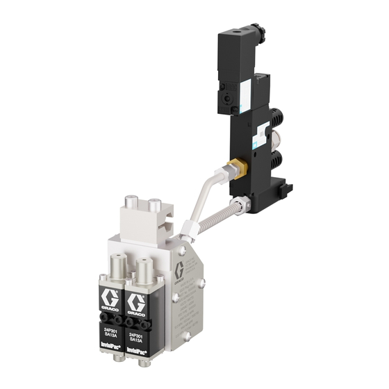
Component Identification Component Identification Identification Component Component Identification Dispense module Fluid outlet/nozzle (3/8–24) Fluid filter (not visible) Manifold Fluid inlet (9/16–18, —6 JIC, 37° flare) Cordset (24W087 shown) Air tube Mounting clamp (1/2 in. diameter bar) Solenoid valve (24 VDC, 110 VAC); not included with all models Muffler Air inlet (3/8 in. -
Page 8: Overview
Overview Overview Grounding Overview Overview Grounding Grounding The valve uses the air-opened, spring closed mode of operation. It uses a three-way exhausting solenoid to control the piston inside the dispense module. Fluid is filtered through the manifold filter (C) before entering the dispense module fluid inlet port. -
Page 9: Installation
Installation Installation Installation Installation Mounting Mounting Mounting 2. Connect the cordset (M) to the hose. 3. Connect the hose inlet to the melter system NOTICE NOTICE NOTICE outlet. See the heated hose manual for installation guidelines. To prevent heat transferring into other components of the packaging line, ensure that the insulator (P) 4. -
Page 10: Connect Triggering Device
Installation Connect Triggering Triggering Device Device Connect Connect Triggering Device 2. Insert a small screwdriver where the mounting screw was removed and gently press the electrical connector (P) out of the electrical Identify if your model uses a 24 VDC or 110 VAC connector housing (N). -
Page 11: Flush
Installation Flush Install Nozzle Nozzle Flush Flush Install Install Nozzle Use 1/2 in. wrench to install nozzle. See Kits and Accessories, page 1. Disconnect or turn off the device which triggers the solenoid valve. 2. Heat the system to working temperature. 3. -
Page 12: Operation
Operation Operation Operation Operation Pressure Relief Relief Procedure Procedure Pressure Pressure Relief Procedure Follow the Pressure Relief Procedure whenever you see this symbol. Material inside the module and hose may still be near setpoint temperature. Wear protective clothing to avoid severe burns. 4. -
Page 13: Maintenance
To establish a preventative maintenance cycle tailored to your Material inside the applicator can be near environment, Graco recommends inspecting filters setpoint temperature. Wear protective clothing every 4 weeks after installation and replacing when to avoid severe burns. -
Page 14: Troubleshooting
Troubleshooting Troubleshooting Troubleshooting Troubleshooting Problem Problem Problem Cause Solution Cause Cause Solution Solution No adhesive or incorrect Debris in manifold filter Replace manifold filter. See amount of adhesive out of all Replace Inlet Filter, page modules when triggered Clogged hose Clean or replace hose. - Page 15 Troubleshooting Problem Cause Solution Problem Problem Cause Cause Solution Solution Gun will not heat Heater failure Check and replace heater cartridge. See Replace Heater Cartridge, page Loose cord set connection Check connection. RTD failure Check and replace RTD. See Check RTD, page Incorrect RTD for adhesive delivery Check delivery system RTD system...
-
Page 16: Check Module
Troubleshooting Problem Cause Solution Problem Problem Cause Cause Solution Solution Adhesive out of all modules Solenoid valve failure Check and replace solenoid valve. when not triggered Adhesive pressure too high Check and reduce fluid pressure. Solenoid valve connected Check solenoid valve air connections. incorrectly Module failure Check and replace all modules. -
Page 17: Check Heater
Troubleshooting Check Heater Heater Check Check Heater Table 1 1 1 24W087, 24W087, Pt Pt Pt 100 100 (385) (385) RTD RTD Cordset Cordset Table Table 24W087, (385) Cordset Description Description Description Check the continuity of the heater to verify proper resistance. -
Page 18: Check Thermal Cutoff
Troubleshooting Check Thermal Thermal Cutoff Cutoff Check Check Thermal Cutoff Thermal Cutoff Cutoff Thermal Thermal Cutoff If working properly, the cutoff will trip at 450°F (232°C) and resets at 370°F (187°C). If failure is suspected, allow gun to cool and then check the continuity of the thermal cutoff to verify it has not failed. -
Page 19: Repair
Repair Repair Repair Repair Required Tools Tools Required Required Tools • Phillips screw driver • Flat blade screw driver • 5/64 in (2 mm) and 5/32 in. (4 mm) Allen wrenches • 1/2 in. and 7/16 in. wrenches • Torque wrench •... -
Page 20: Replace Heater Cartridge
Repair Replace Heater Heater Cartridge Cartridge Replace Replace Heater Cartridge 2. Use a Phillips screws driver to remove the four screws (15) and manifold cover plate (52). 1. Disable gun assembly. 3. Remove splices from heater wires (3) and 2. Use a Phillips screwdriver to remove screws (15) cordset wire leads (17). - Page 21 Repair Wiring Diagram Diagram Wiring Wiring Diagram Thermal Thermal Thermal Cutoff Cutoff Cutoff Note Slim (24U021–24U026) and Low Profile Dual (24U026–24U032) applicators use one heater (3). 3A2805M...
-
Page 22: Replace Cordset
Repair Replace Cordset Cordset Replace Replace Cordset 5. Remove the RTD (R) from the manifold (1). Note On guns that are not low profile, if the Note RTD does not easily pull out, remove the other cover plate (19) and press out with There are two types of cordsets (17): a small screwdriver. - Page 23 Repair 10. Reinstall the ground lead onto the manifold (1). NOTICE NOTICE NOTICE Note To prevent removing wire insulation or disconnecting wires, do not pinch any wires Ensure the star washer (20) is placed when inserting wire in the manifold. If wire below the ground ring terminal.
-
Page 24: Replace Solenoid Valve
Repair Replace Solenoid Solenoid Valve Valve Replace Replace Solenoid Valve NOTICE NOTICE NOTICE Do not allow adhesive to enter the air ports, 1. Disable gun assembly. See to allow air to flow through valve. Adhesive in Before Beginning Repair, page the air ports will obstruct the flow of air and 2. -
Page 25: Notes
Notes Notes Notes Notes 3A2805M... -
Page 26: Parts
Parts Parts Parts Parts Single GS35 GS35 Single Single GS35 Apply anti-seize to first 1/2 in. of threads. Torque Apply thread sealant to threads. to 28-32 in-lbs (3.2-3.6 N∙m). Apply a thin coating of lubricant to seals. Wiring Diagram, page 3A2805M... - Page 27 Parts Table 3 3 3 Single Single GS35 GS35 Table Table Single GS35 Quantity Quantity Quantity Part Description 24P073 24P074 24P074 24P246 24P246 24P299 24P299 24P300 24P300 24P307 24P307 Part Part Description Description 24P073 24P073 24P074 24P246 24P299 24P300 24P307 - - - HOUSING, single - - -...
- Page 28 Parts DUAL GS35 GS35 DUAL DUAL GS35 Apply anti-seize to first 1/2 in. of threads. Torque Apply thread sealant to threads. to 28-32 in-lbs (3.2-3.6 N∙m). Apply a thin coating of lubricant to seals. Wiring Diagram, page 3A2805M...
- Page 29 Parts Table 4 4 4 Dual Dual GS35 GS35 Table Table Dual GS35 Part Description 24P075 24P076 24P076 24P247 24P247 24P301 24P301 24P302 24P302 24P308 24P308 Part Part Description Description 24P075 24P075 24P076 24P247 24P301 24P302 24P308 - - - HOUSING, dual - - - 2●...
- Page 30 Parts Quad GS35 GS35 Quad Quad GS35 24P077 Type I Shown Apply anti-seize to first 1/2 in. of threads. Torque Apply thread sealant to threads. to 28-32 in-lbs (3.2-3.6 N∙m). Apply a thin coating of lubricant to seals. Wiring Diagram, page 3A2805M...
- Page 31 Parts Table Table 5 5 5 Quad Table Quad Quad GS35 GS35 With GS35 With With 0.88 0.88 in. in. 0.88 in. Spaced Spaced Spaced Manifold Manifold Manifold (Type (Type I) I) I) (Type Quantity Quantity Quantity 24P077 24P078 24P078 24P250 24P250 24P303 24P303 24P304 24P304 24P309...
- Page 32 Parts Table Table Table 6 6 6 Quad Quad Quad GS35 GS35 with GS35 with with 1.5 1.5 in. in. in. Spaced Spaced Spaced Manifold Manifold Manifold (Type (Type II) II) II) (Type Quantity Quantity Quantity 24P079 24P080 24P254 24P305 24P306 24P310 24P079...
- Page 33 Parts Notes Notes Notes 3A2805M...
- Page 34 Parts Slim GS35 GS35 Slim Slim GS35 Apply anti-seize to first 1/2 in. of threads. Torque Apply thread sealant to threads. to 28-32 in-lbs (3.2-3.6 N∙m)). Apply a thin coating of lubricant to seals. Wiring Diagram, page 3A2805M...
- Page 35 Parts Table 7 7 7 Slim Slim GS35 GS35 Table Table Slim GS35 Quantity Quantity Quantity Part Description 24U021 24U022 24U023 24U024 24U025 24U026 Part Part Description Description 24U021 24U021 24U022 24U022 24U023 24U023 24U024 24U024 24U025 24U025 24U026 24U026 - - - HOUSING, slim - - -...
- Page 36 Parts Low Profile Profile Dual Dual GS35 GS35 Profile Dual GS35 Apply anti-seize to first 1/2 in. of threads. Torque Apply thread sealant to threads. to 28-32 in-lbs (3.2-3.6 N∙m)). Apply a thin coating of lubricant to seals. Wiring Diagram, page 3A2805M...
- Page 37 Parts Table Table 8 8 8 Low Table Low Profile Profile Dual Profile Dual GS35 Dual GS35 GS35 Quantity Quantity Quantity Description Part Part Part Description Description 24U027 24U027 24U028 24U027 24U028 24U029 24U028 24U029 24U029 24U030 24U030 24U030 24U031 24U031 24U031 24U032 24U032...
- Page 38 Parts Quantity Quantity Quantity Part Description Description Description 24U027 24U028 24U028 24U029 24U029 24U030 24U030 24U031 24U031 24U032 24U032 Part Part 24U027 24U027 24U028 24U029 24U030 24U031 24U032 KIT, THERMAL CUTOFF (includes 24V794 52a-52c) - - - PLATE, with thermal cutoff CONNECTOR, splice, 14–16 AWG, heat - - - resistant...
- Page 39 Parts Notes Notes Notes 3A2805M...
- Page 40 Parts Low Profile Profile Quad Quad GS35 GS35 Profile Quad GS35 Apply anti-seize to first 1/2 in. of threads. Torque Apply thread sealant to threads. to 28-32 in-lbs (3.2-3.6 N∙m)). Apply a thin coating of lubricant to seals. Wiring Diagram, page 3A2805M...
- Page 41 Parts Table Table 9 9 9 Low Table Low Profile Profile Quad Profile Quad GS35 Quad GS35 GS35 Quantity Quantity Quantity 24U033 24U034 24U035 24U036 24U037 24U038 24U033 24U033 24U034 24U034 24U035 24U035 24U036 24U036 24U037 24U037 24U038 24U038 Description Part Part Part...
- Page 42 Parts Quantity Quantity Quantity 24U033 24U033 24U033 24U034 24U034 24U034 24U035 24U035 24U035 24U036 24U036 24U036 24U037 24U037 24U037 24U038 24U038 24U038 Part Description Description Description Part Part 24V796 KIT, THERMAL CUTOFF (includes 52a-52c) - - - PLATE, with thermal cutoff - - - CONNECTOR, splice, 14–16 AWG, heat resistant...
- Page 43 Parts Solenoid Valve Valve Kits Kits Solenoid Solenoid Valve Kits 24P239, 24P239, 24P239, 24 24 VDC VDC Solenoid Solenoid Valve Solenoid Valve Valve 24P240, 24P240, 24P240, 110 110 VAC VAC Solenoid Solenoid Valve Solenoid Valve Valve Apply thread sealant to threads. Part Description Part...
-
Page 44: Kits And Accessories
Kits and Accessories Kits and and Accessories Accessories Kits Kits Accessories Module Replacement Replacement Heater Cartridges Cartridges Module Module Replacement Heater Heater Cartridges 24P241 24P241 24P241 Heater cartridges for single, dual, and quad manifolds with butt splices, tape, and tubing. See See manual 407050. - Page 45 Kits and Accessories Mufflers Mounting Clamp Clamp Kits Kits Mufflers Mufflers Mounting Mounting Clamp Kits 24P282 24P282 24P282 Models, page 6 , for model numbers. Includes two mufflers that can be used with solenoid 24P277 24P277 24P277 (Single, (Single, (Single, Dual, Dual, Dual, and and Quad...
-
Page 46: Dimensions
Dimensions Dimensions Dimensions Dimensions Single, Dual, Dual, and and Quad Quad GS35 GS35 Single, Single, Dual, Quad GS35 24P075 Shown 0.72 in. 0.79 in. (18.16 mm) (20.0 mm) 4.24 in. (107.7 mm) 3.63 in. (92.2 mm) 1.14 in. 1.00 in. (28.96 mm) (25.4 mm) 3.07 in. - Page 47 Dimensions Slim GS35 GS35 Slim Slim GS35 (24U021-24U026) 24U021 24U021 Shown 24U021 Shown Shown 11.68 in. (296.67 mm) 0.79 in. (20.0 mm) 2.41 in. (61.21 mm) 5.01 in. (127.25 mm) 4.24 in. (107.70 mm) 3.63 in. (92.20 mm) 2.86 in. (72.64 mm) 0.67 in.
- Page 48 Dimensions Low Profile Profile Double Double GS35 GS35 Profile Double GS35 (24U027-24U033) 24U027 24U027 24U027 Shown Shown Shown 11.69 in. (296.93 mm) 0.79 in. (20.1 mm) 3.18 in. (80.77 mm) 1.5 in. (38.1 mm) 1.0 in. 2.30 in. (25.4 mm) (58.42 mm) 0.88 in.
- Page 49 Dimensions Low Profile Profile Quad Quad GS35 GS35 Profile Quad GS35 (24Ubob 033-24U038) 24U033 24U033 Shown 24U033 Shown Shown 11.69 in. (296.93 mm) 0.79 in. (20.1 mm) 3.18 in. (80.77 mm) 1.5 in. 1.0 in. (38.1 mm) (25.4 mm) 2.30 in. (58.42 mm) 0.88 in.
-
Page 50: Technical Data
Technical Data Technical Data Data Technical Technical Data InvisiPac InvisiPac InvisiPac ™ ™ ™ GS35 GS35 Plug GS35 Plug Plug- - - Free Free Free Hot Hot Melt Melt Adhesive Melt Adhesive Adhesive Applicator Applicator Applicator Metric Metric Metric Speed >... -
Page 51: Notes
Notes Notes Notes Notes 3A2805M... -
Page 52: Graco Extended Warranty
With the exception of any special, extended, or limited warranty published by Graco, Graco will, for a period of eighteen months from the date of sale, repair or replace any part of the equipment determined by Graco to be defective. This warranty applies only when the equipment is installed, operated and maintained in accordance with Graco’s written recommendations.
Need help?
Do you have a question about the InvisiPac GS35 Plug-Free and is the answer not in the manual?
Questions and answers